
Chapter 9
802.11 Security
In this chapter, you will learn about the following:
- Authentication
- Open System Authentication
- Shared Key Authentication
- WLAN Encryption Methods
- WEP
- TKIP
- CCMP
- WPA/WPA2
- Robust Security Networks (RSN)
- RSN Information Element
- 802.1X
- Supplicant
- Authenticator
- Authentication Server
- EAP
- Strong EAP Protocols
- EAP-PEAP
- 4-Way Handshake
- Group Key Handshake
- FastBSS Transition (FT)
- Information Elements
- FT Initial Mobility Domain Association
- Over-the-air Fast BSS Transition
- Over-the-DS Fast BSS Transition
- 802.11w Protected Management Frames
In this chapter, we will cover 802.11 security, highlighting some of the frame exchanges and changes to frames when security is enabled. The focus of this book is 802.11 analysis and not security. If you would like to learn more about 802.11 security, you should consider reading CWSP Certified Wireless Security Professional Official Study Guide: Exam PW0-204 (Sybex, 2010).
Authentication is the first of two steps required to connect to the 802.11 basic service set. Both authentication and association must occur, in that order, before an 802.11 client can pass traffic through the access point to another device on the network. Authentication is a process that is often misunderstood. When many people hear authentication, they think of what is commonly referred to as network authentication, in other words, entering a username and password in order to get access to the network. In this chapter, we are referring to 802.11 authentication that occurs at layer 2 of the OSI model. When an 802.3 device needs to communicate with other devices, the first step is to plug the Ethernet cable into a wall jack. When this cable is plugged in, the client creates a physical link to the wired switch and is now able to start transmitting frames. When an 802.11 device needs to communicate, it must first authenticate with the access point. This authentication is not much more of a task than plugging the Ethernet cable into the wall jack. The 802.11 authentication merely establishes an initial connection between the client and the access point, basically validating or authenticating that the STA is a valid 802.11 device. The 802.11-2007 standard specifies two different methods of authentication: Open System authentication and Shared Key authentication.
Open System Authentication
Within a basic service set (BSS), Open System authentication occurs with an exchange of frames between the client station and the access point station. Open System authentication utilizes a two-message authentication transaction sequence. The client that is looking to join the BSS sends the first message, which in itself is essentially asserting its 802.11 identity and requesting authentication to the BSS. The second message returns the authentication result. If the result is “successful,” the STAs will be declared mutually authenticated, both identified as 802.11 devices. Open System authentication is also used by STAs in an independent basic service set (IBSS), which is more commonly known as an ad hoc WLAN.
Open System authentication occurs after a client STA knows about the existence of an access point (AP) by either passive or active scanning. The client STA can passively find out about the parameters of the BSS from the AP’s beacon management frame or extract the same information during the active probing process from the AP’s probe response frame. An Open System authentication frame exchange process then begins with the goal of eventually joining the BSS. As shown in Figure 9-1, the client STA must first become authenticated before exchanging two more association frames. Once Open System authentication and association occurs, the client STA establishes a layer 2 connection to the AP and is a member of the BSS.
Figure 9-1: Open System authentication
WEP encryption is optional with Open System authentication. For data privacy, Wired Equivalent Privacy encryption can be used with Open System authentication, but WEP is used only to encrypt the layers 3–7 MAC Service Data Unit (MSDU) payload of 802.11 data frames and only after the client station is authenticated and associated. In other words, WEP is not used as part of the Open System authentication process, but WEP encryption can be used to provide data privacy after authentication and association occur. So, if Open System authentication is so simple and basic—providing no verification of identity—then why is it still used when security is so important? The answer to this question is simple. It doesn’t need to be secure, because other more advanced overlay security authentication methods such as 802.1X/EAP are now being implemented. As you can see in Figure 9-2, Open System authentication and association between the client STA and AP still occurs prior to the 802.1X/EAP authentication exchange between the client STA and a RADIUS server. In Exercise 9-1, you will look at a packet capture containing Open System authentication frames.
The 802.11-2007 standard now defines more advanced authentication methods. A more detailed discussion about 802.1X/EAP can be found later in this chapter and in CWSP Certified Wireless Security Professional Official Study Guide: Exam PW0-204.
Figure 9-2: Open System and 802.1X/EAP authentication

Shared Key Authentication
Shared Key authentication is a four-way authentication frame exchange, as shown in Figure 9-3. Shared Key authentication requires WEP to authenticate the client station. The client station sends an authentication request to the AP, and the AP sends a clear-text challenge to the client station in an authentication response. The client station then encrypts the clear-text challenge and sends it back to the AP in the body of another authentication request frame. The AP decrypts the station’s response and compares it to the challenge text. If they match, the AP will respond by sending a fourth and final authentication frame, an authentication response frame to the station, confirming successful authentication. If they do not match, the AP will respond negatively. If the WEP ICV check fails or if the AP cannot decrypt the challenge, it will also respond negatively. If Shared Key authentication is successful, the same static WEP key that was used during the Shared Key authentication process will also be used to encrypt the 802.11 data frames.
When WEP is enabled, it might seem that Shared Key authentication is a more secure solution than Open System authentication, in reality Shared Key could be the bigger security risk. Anyone who captures the clear-text challenge phrase and then captures the encrypted challenge phrase in the response frame could potentially derive the static WEP key. If the static WEP key is compromised, a whole new can of worms has been opened because now all the data frames can be decrypted.
Do not confuse the Shared Key authentication with Preshared Key (PSK) authentication. Shared Key authentication is a legacy method defined as a pre-RSNA security method. The 802.11-2007 standard defines robust security that requires either 802.1X/EAP authentication or PSK authentication. PSK authentication methods are discussed later in this chapter and in CWSP Certified Wireless Security Professional Official Study Guide: Exam PW0-204.
Figure 9-3: Shared Key authentication exchange

In Exercise 9-1, you will look at packet captures containing encrypted and decrypted Shared Key authentication frames.
Exercise 9-1
Viewing Open System and Shared Key Authentication Frames
In this exercise, you will use a protocol analyzer to view the 802.11 frame exchanges used to authenticate a client to the access point. To perform the exercises in this chapter, we will walk you through using Wireshark. The following directions should assist you with locating, downloading, and installing Wireshark. If you are familiar with another protocol analyzing software, feel free to use it to perform this lab. If you have already installed Wireshark, you can skip steps 1–4.
1. In your web browser, go to the Wireshark website: www.wireshark.org.
2. Click the Download Wireshark button to locate the installation file, and download the file that is appropriate for your operating system.
3. After downloading the file, double-click it to proceed with the installation, and follow the installation directions.
4. The exercise will use frame captures that are on the book’s companion CD. If you would like to use Wireshark for live wireless captures (and you are running Windows), you will have to purchase an AirPcap adapter from Cace Technologies (www.cacetech.com).
5. In Windows, choose Start All Programs, and then click the Wireshark icon. The Wireshark application should appear.
6. In the center section, click the Open icon, and browse to the book’s CD.
7. Open the packet capture file called OPEN_SYSTEM_AUTHENTICATION.PCAP.
The file will open, and Wireshark will display three sections:
- The top section is called the packet list, displaying a list of the individual packets.
- The middle section is called the packet detail, displaying as much detail about each packet as possible.
- The bottom section shows the bytes in the current packet.
When you click packet 1 in the packet list, Wireshark will display the packet detail in the middle section of the window.
8. Click the + next to IEEE 802.11 Wireless LAN Management Frame to expand that section, and then click the + to expand the Fixed Parameters (6 Bytes) section.
If you look in this section, you will see Authentication Algorithm is Open System and Authentication Seq Num is 1. This indicates it is an Open System authentication request frame.
In the packet list section, if you click the third packet, in the packet detail section you will see Authentication Algorithm is Open System and Authentication Seq Num is 2. This indicates it is an Open System authentication reply frame. You can also see that Status Code indicates that the authentication was successful.
9. Go to the File menu, and select Close. This will bring you back to the initial Wireshark screen.
10. In the center section, click the Open icon, and browse the book’s CD.
11. Open the packet capture file called SHARED_KEY_AUTHENTICATION_ENCRYPTED.PCAP.
The two packets of most interest are packets 3 and 5. In packet 3, the access point is responding to the authentication request and including the challenge text unencrypted.
12. Expand the IEEE 802.11 Wireless LAN Management Frame section, and you will see the challenge text.
13. Select packet 5. This frame is the response from the client to the access point. The client has taken the challenge text and encrypted it. If you expand the IEEE 802.11 Authentication section, you will see the WEP parameters, and if you expand the Data section, you will see 136 bytes of encrypted data.
14. Go to the File menu, and select Close.
15. In the center section, click the Open File icon, and browse to the book’s CD.
16. Open the packet capture file called SHARED_KEY_AUTHENTICATION_DECRYPTED.PCAP.
17. This file is a decrypted version of the file you were just looking at. Repeat steps 12 and 13 using the decrypted file.
The 802.11-2007 standard defines three encryption methods that operate at layer 2 of the OSI model: Wired Equivalent Privacy (WEP), Temporal Key Integrity Protocol (TKIP), and CTR with CBC-MAC Protocol (CCMP). The information that is being protected by these layer 2 encryption methods is data found in the upper layers of 3–7. Layer 2 encryption methods are used to provide data privacy for 802.11 data frames.
The 802.11 data frame, or MAC Protocol Data Unit (MPDU), as shown in Figure 9-4, contains a layer 2 MAC header, a frame body, and a trailer, which is a 32-bit CRC known as the frame check sequence (FCS). The layer 2 header contains MAC addresses and the Duration value. Encapsulated inside the frame body of an 802.11 data frame is the upper-layer payload, the MAC Service Data Unit (MSDU). The MSDU contains data from the Logical Link Control (LLC) and layers 3–7. The MSDU is the data payload that contains an IP packet plus some LLC data. The 802.11-2007 standard states that the MSDU payload can be anywhere from 0 to 2,304 bytes. The frame body may actually be larger because of encryption overhead.
WEP, TKIP, CCMP, and other proprietary layer 2 encryption methods are used to encrypt the MSDU payload of an 802.11 data frame. Therefore, the information that is being protected is the upper layers of 3–7, more commonly known as the IP packet. The current 802.11-2007 standard defines WEP as a legacy encryption method for prerobust security network association (pre-RSNA) security. TKIP and CCMP are considered to be compliant robust security network (RSN) encryption protocols.
Figure 9-4: 802.11 MAC Protocol Data Unit
WEP
Wired Equivalent Privacy is a layer 2 security protocol that uses the RC4 streaming cipher. The original 802.11 standard defined both 64-bit WEP and 128-bit WEP as supported encryption methods. The current 802.11-2007 standard still defines WEP as a legacy encryption method for pre-RSNA security. The Wi-Fi Alliance has been certifying 802.11 radios using WEP encryption since 2000.
64-bit WEP uses a secret 40-bit static key, which is combined with a 24-bit number selected by the card’s device drivers. This 24-bit number, known as the initialization vector (IV), is sent in clear text and is different on every frame. Although the IV is said to be different on every frame, there are only 16,777,216 different IV combinations; therefore, you are forced to reuse the IV values. 128-bit WEP encryption uses a 104-bit secret static key that is also combined with a 24-bit IV. Because of the 24-bit IV that is added to the WEP key by the device driver, the 802.11-2007 standard refers to 64-bit WEP as WEP-40 and 128-bit WEP as WEP-104.
As shown in Figure 9-5, the static key and the IV are used as WEP seeding material through the pseudorandom RC4 algorithm that generates the keystream. The pseudorandom bits in the keystream are then combined with the plain-text data bits by using a Boolean XOR process. The end result is the WEP cipher text, which is the encrypted data. WEP also runs a cyclic redundancy check (CRC) on the plain-text data that is to be encrypted and then appends the integrity check value (ICV) to the end of the plain-text data. The ICV is used for data integrity and should not be confused with the IV, which is part of the seeding material for the RC4 cipher.
If You Thought WEP Used RC4 Encryption, You Are Right and Wrong!
RC4 is also known as ARC4 or Arcfour. ARC4 is short for Alleged RC4. RC4 was created in 1987 by Ron Rivest of RSA Security. It is known as either Rivest Cipher 4 or Ron’s Code 4. RC4 was initially a trade secret; however, in 1994, a description of it was leaked onto the Internet. Comparison testing confirmed that the leaked code was genuine. RSA has never officially released the algorithm, and the name RC4 is trademarked, which is why it’s called Arcfour or ARC4.
Figure 9-5: WEP encryption process
The encryption and decryption process for WEP is the same whether you are using WEP-40 or WEP-104. Figure 9-6 shows the WEP frame body, which contains an encrypted MSDU. To create the WEP-encrypted MSDU, WEP runs a cyclic redundancy check on the plain-text data that is to be encrypted and then appends the ICV to the end of the plain-text data. The ICV adds 32 bits (4 octets) of overhead to an 802.11 data frame. The data and ICV are then encrypted. WEP can be configured with up to four different keys. A Key ID identifies which WEP key was combined with the system-generated 24-bit IV to perform the encryption. This 24-bit IV is combined with the Key ID and 6 bits of padding to create a 32-bit IV. The IV adds 32 bits (4 octets) of overhead to the frame body of an 802.11 data frame. The IV is not encrypted and is appended to the front of the encrypted MSDU payload.
Bits, Bytes, Octets
A bit is a binary digit, taking a value of either 0 or 1. Binary digits are a basic unit of communication in digital computing. A byte of information comprises 8 bits. An octet is another name for one byte of data. The CWAP exam uses the terminology of octet and byte interchangeably.
Remember that WEP encrypts the MSDU upper-layer payload that is encapsulated in the frame body of an MPDU. The MSDU payload has a maximum size of 2,304 bytes. Because the IV adds 4 octets and the ICV also adds 4 octets, when WEP is enabled, the entire size of the body inside an 802.11 data frame is expanded by 8 bytes to a maximum of 2312 bytes. In other words, WEP encryption adds 8 bytes of overhead to an 802.11 MPDU.
Figure 9-6: WEP MPDU format
TKIP
TKIP is an enhancement of WEP. Like WEP, TKIP uses the ARC4 algorithm for performing its encryption and decryption processes. The TKIP enhancements were also intended to address the many known weaknesses of WEP. TKIP uses dynamically created encryption keys as opposed to the static keys. Any two radios use a 4-Way Handshake process to create dynamic unicast keys that are unique to those two radios.
Figure 9-7 shows the TKIP encryption and data integrity process. It will be helpful to refer to this figure as you read about the steps TKIP performs.
TKIP starts with a 128-bit temporal key. An often-asked question is “Where does the 128-bit temporal key come from?” The answer is that the 128-bit temporal key is a dynamically generated key that comes from a 4-Way Handshake creation process. This key is identical on the AP and client pair. The 128-bit temporal key can either be a pairwise transient key (PTK) used to encrypt unicast traffic or a group temporal key (GTK) used to encrypt broadcast and multicast traffic.
After the appropriate 128-bit temporal key (pairwise or group) is created, the two-phase key-mixing process begins. A 48-bit TKIP sequence counter (TSC) is generated and broken into 6 octets labeled TSC0 (least significant octet) through TSC5 (most significant octet). Phase 1 key mixing combines the 128-bit temporal key (TK) with the TSC2 through TSC5 octets of the TSC as well as the transmit address (TA). The TA is the MAC address of the transmitting 802.11 radio. The output of the Phase 1 key mixing is the creation of the TKIP-mixed transmit address and key (TTAK).
After the TTAK is generated, the Phase 2 key mixing can begin. Phase 2 key mixing combines the TTAK with the TSC0 and TSC1 octets of the TSC with the 128-bit TK. The output of the Phase 2 key mixing is referred to as the WEP seed. This WEP seed is then run through the ARC4 algorithm, and the keystream is created. The WEP seed is represented as a WEP IV and 104-bit WEP key when fed into the ARC4 algorithm. You may often hear TKIP referenced as using a 48-bit IV. During the Phase 2 key mixing process, TKIP encodes the TSC value from the sender as a WEP IV and an extended IV. The encoding of the 48-bit TSC effectively creates a 48-bit IV.
The two-phase key-mixing process can be summarized as follows:
- TTAK = Phase 1 (TK, TA, TSC)
- WEP seed = Phase 2 (TTAK, TK, TSC)
TKIP uses a stronger data integrity check known as the message integrity code (MIC) to mitigate known forgery attacks against WEP. The MIC is often referred to by its nickname of Michael. The MIC can be used to defeat bit-flipping attacks, fragmentation attacks, redirection, and impersonation attacks. The MIC is computed using the destination address (DA), the source address (SA), the MSDU priority, and the entire unencrypted MSDU plain-text data. After the MIC is generated, it is appended the end of the MSDU payload. The MIC is 8 octets in size and is labeled individually as M0 through M7. The MIC contains only 20 bits of effective security strength, making it somewhat vulnerable to brute-force attacks. Because the MIC only provides weak protection against active attacks, the 802.11-2007 standard defines TKIP countermeasures procedures. The TKIP countermeasures include the following.
Figure 9-7: TKIP encryption and data integrity process
The TKIP MIC augments, but does not replace, the WEP ICV. TKIP protects the MIC with encryption, which makes TKIP MIC forgeries more difficult. The WEP ICV helps prevent false detection of MIC failures that would cause the countermeasures to be invoked.
After the MIC is created and appended to the plain-text MSDU, the 802.11 MAC performs its normal processing on this MSDU. If fragmentation is enabled, it is possible that this could be broken up into one or more MPDUs. It is even possible for the MIC to wind up split between two MPDUs. To keep things simple, we will assume that only one MPDU is created. An integrity check is performed on the plain-text MPDU, and the WEP ICV is then appended to the MPDU. A Boolean XOR is then performed on the keystream and the MPDU/ICV to generate the encrypted payload. A frame check sequence is calculated over all the fields of the header and entire frame body. The resulting 32-bit CRC is then placed in the FCS field.
Before verifying the MIC, a receiving 802.11 STA will check the FCS, ICV, and TSC of all MPDUs. Any MPDU that has an invalid FCS, an incorrect ICV, or a TSC value that is less than or equal to the TSC replay counter is dropped before checking the MIC. This avoids unnecessary MIC failure events. Checking the TSC before the MIC makes countermeasure-based DoS attacks harder to perform. Checking the TSC also protects against replay/injection attacks. Although considered weak for data integrity protection, the ICV also offers some error detection. If the MPDU is corrupted by multipath interference or collisions, the FCS fails, and the entire MPDU must be retransmitted. After the FCS, ICV, and TSC are checked, the MIC is used for verification of data integrity.
Figure 9-8 shows the TKIP MPDU. The first 32 bytes are the 802.11 MAC header, which does not change. The encrypted frame body consists of five key pieces:
- IV/Key ID
- Extended IV
- MSDU payload
- MIC
- ICV
It begins with the IV/Key ID combination. This is 4 octets in size and is similar to the IV/Key ID that is found in WEP. TSC0 and TSC1, the first two octets of the 48-bit TKIP sequence counter (TSC0 and TSC1), make up part of the IV/Key ID. If TKIP is being used, which is the case in this example, the Extended IV field is set to 1, indicating that an extended IV of 4 octets will follow the original IV. The Extended IV is 4 octets and is made up of the other 4 octets of the 48-bit TKIP sequence counter (TSC2 through TSC5). Both the original IV and the Extended IV are not encrypted. The 8 bytes that comprise the IV/Key ID and Extended IV could be considered a TKIP header.
Figure 9-8: TKIP MPDU
After the original IV and the Extended IV comes the MSDU payload, followed by the 8 MIC octets, which is then followed by the 32-bit ICV that was calculated on the MPDU. The MSDU upper-layer payload as well as the MIC and ICV are all encrypted. The frame is then completed by adding the 32-bit frame check sequence (FCS) that is calculated over all the fields of the header and frame body.
Because of the extra overhead from the IV (4 bytes), Extended IV (4 bytes), MIC (8 bytes), and ICV (4 bytes), a total of 20 bytes of overhead is added to the frame body of a TKIP-encrypted 802.11 data frame. When TKIP is enabled, the entire size of the frame body inside an MPDU is expanded by 20 bytes to a maximum of 2,324 bytes. In other words, TKIP encryption adds 20 bytes of overhead to an 802.11 MPDU.
Exercise 9-2
TKIP-Encrypted Frames
In this exercise, you will use a protocol analyzer to view 802.11 data frames encrypted with TKIP. The following directions should assist you with locating, downloading, and installing Wireshark. If you are familiar with another protocol analyzing software, feel free to use it to perform this lab. If you have already installed Wireshark, you can skip steps 1–4.
1. In your web browser, go to the Wireshark website: www.wireshark.org.
2. Click the Download Wireshark button to locate the installation file, and download the file that is appropriate for your operating system.
3. After downloading the file, double-click it to proceed with the installation, and follow the installation directions.
The exercise will use frame captures that are on the CD that came with this book. If you would like to use Wireshark for live wireless captures (and you are running Windows), you will have to purchase an AirPcap adapter from Cace Technologies (www.cacetech.com).
4. In Windows, choose Start All Programs, and then click the Wireshark icon. The Wireshark application should appear.
5. In the center section, click the Open icon, and browse the book’s CD.
6. Open the packet capture file called TKIP_FRAMES.PCAP.
7. The file will open, and Wireshark will display its three sections. If you click one of the 802.11 TKIP data packets (listed in the Info column), Wireshark will display the details of the frame in the middle section.
8. If you click one of the beacons with the source address of 00:1A:1E:94:4C:31, Wireshark will display the details of the beacon frame in the middle section. If you expand the frame and scroll down, you will see the cipher TKIP is listed.
CCMP
CCMP consists of many components that provide different functions. Before going any further in this section, there are numerous acronyms and abbreviations relating to CCMP to which you need to be introduced. These acronyms and abbreviations are commonly used in the wireless industry and in the IEEE 802.11-2007 standard. Since CCMP consists of many different components, it is common to reference the components individually. Counter mode is often represented as CTR. CTR is used to provide data confidentiality. The acronym for cipher-block chaining is CBC. You should also be familiar with CBC-MAC, which is the acronym for cipher-block chaining message authentication code (CBC-MAC). The CBC-MAC is used for authentication and integrity.
The full phrase of counter mode with the Cipher-Block Chaining Message Authentication Code protocol is represented by the acronym of CCMP. However, the shorter phrase of CTR with CBC-MAC is also sometimes represented by the CCMP acronym.
Some references to CCMP leave off the letter P and use the term CCM when referencing the block cipher and not the actual protocol. CCMP is based on the CCM of the AES encryption algorithm. CCM combines CTR to provide data confidentiality and CBC-MAC for authentication and integrity. In much simpler words, the CCM process uses the same key for encrypting the MSDU payload and provides for a cryptographic integrity check. The integrity check is used to provide data integrity for both the MSDU data and portions of the MAC header of the MPDU.
CCM is used with the AES block cipher. Although it is capable of using different key sizes, when implemented as part of the CCMP encryption method, AES uses a 128-bit key and encrypts the data in 128-bit blocks.
Figure 9-9 shows the CCMP encryption and data integrity process. It will be helpful to refer to this figure as you read about the steps CCMP performs.
CCMP encrypts the payload of a plain-text MPDU using the following steps:
1. A 48-bit packet number (PN) is created. Packet numbers increment with each individual MPDU, although they remain the same for retransmissions.
2. As shown in Figure 9-10, certain fields in the MPDU header are used to construct the additional authentication data (AAD). Additional authentication data is constructed from portions of the MPDU header. This information is used for data integrity of portions of the MAC header. Receiving stations can then validate the integrity of these MAC header fields.
Figure 9-9: CCMP encryption and data integrity process
Figure 9-10: Additional authentication data (AAD)
The MIC provides integrity protection for these fields in the MAC header as well as for the frame body. All of the MAC addresses, including the BSSID, are protected. Portions of the other fields of the MAC header are also protected. Receiving stations will validate the integrity of these protected portions of the MAC header. For example, the frame type and the distribution bits that are subfields of the Frame Control field are protected. Receiving stations will validate the integrity of these protected portions of the MAC header. The AAD does not include the header Duration field, because the Duration field value can change because of normal IEEE 802.11 operation. For similar reasons, several subfields in the Frame Control field, the Sequence Control field, and the QoS Control field are masked to 0 and therefore are not protected. For example, the Retry bit and Power Management bits are also masked and are not protected by CCM integrity.
3. A nonce is created from the packet number (PN), transmitter address (TA), and priority data used in QoS.
4. The 8-octet CCMP header is constructed. The CCMP header includes the Key ID and the packet (PN), which is divided into 6 octets. You will notice that the construction of the CCMP header is basically identical to the 8-octet TKIP header.
5. The CCM module, which uses the AES clock cipher, will now be used to create a data integrity check and encrypt the upper-layer data. The 128-bit temporal key, the nonce, the AAD, and the plain-text data are then processed to create an 8-byte MIC. The MSDU payload of the frame body and the MIC are then encrypted in 128-bit blocks. This process is known as CCM originator processing.
6. The original MAC header is appended to the CCMP header, the encrypted MSDU, and the encrypted MIC. A frame check sequence is calculated over all of the fields of the header and entire frame body. The resulting 32-bit CRC is then placed in the FCS field.
Figure 9-11 shows the CCMP MPDU. The first 32 bytes are the 802.11 MAC header, which does not change. The frame body consists of the CCMP header, the MSDU upper-layer payload, and the MIC. The CCMP header includes the one octet Key ID and the 48-bit packet (PN), which is spread across 6 octets. You will notice that the format of the CCMP header is basically identical to the format of the 8-octet TKIP header (IV/Extended IV). The CCMP header is not encrypted. The MSDU payload and the 8-byte MIC are encrypted.
The overhead that results from CCMP encryption includes the CCMP header (8 bytes) and the MIC (8 bytes). When CCMP is enabled, the entire size of the frame body inside an MPDU is expanded by 16 bytes to a maximum of 2,320 bytes. In other words, CCMP encryption adds 16 bytes of overhead to an 802.11 MPDU.
Figure 9-11: CCMP MPDU

Exercise 9-3
CCMP-Encrypted Frames
In this exercise, you will use a protocol analyzer to view 802.11 data frames encrypted with CCMP. The following directions should assist you with locating, downloading, and installing Wireshark. If you are familiar with another protocol analyzing software, feel free to use it to perform this lab. If you have already installed Wireshark, you can skip steps 1–4.
1. In your web browser, go to the Wireshark website: www.wireshark.org.
2. Click the Download Wireshark button to locate the installation file, and download the file that is appropriate for your operating system.
3. After downloading the file, double-click it to proceed with the installation, and follow the installation directions.
4. The exercise will use frame captures that are on the CD that came with this book. If you would like to use Wireshark for live wireless captures (and are running Windows), you will have to purchase an AirPcap adapter from Cace Technologies (www.cacetech.com).
5. In Windows, choose Start All Programs, and then click the Wireshark icon. The Wireshark application should appear.
6. In the center section, click the Open icon, and browse to the book’s CD. Open the packet capture file called CCMP_FRAMES.PCAP.
7. The file will open, and Wireshark will display its three sections. If you click one of the beacons with the source address of 00:1A:1E:94:4C:32, Wireshark will display the details of the frame in the middle section. If you expand the frame and scroll down to the RSN section, you will see the cipher AES (CCM) listed.

Why does the WLAN protocol analyzer display CCMP-encrypted data frames as TKIP-encrypted data packets? As you have already learned, the format of the 8-byte CCMP header is basically identical to the format of the 8-byte TKIP header (IV/Extended IV) used by TKIP. Therefore, most protocol analyzers cannot distinguish between TKIP-encrypted data frames and CCMP-encrypted data frames. However, you can always determine which cipher is being used by looking at a field called the RSN information element. The RSN information element is found in four different 802.11 management frames: beacon management frames, probe response frames, association request frames, and reassociation request frames.
Prior to the ratification of the 802.11i amendment, the Wi-Fi Alliance introduced the Wi-Fi Protected Access (WPA) certification. WPA was a snapshot of the not-yet-released 802.11i amendment, but the WPA certification only required support for TKIP/RC4 dynamic encryption key generation. 802.1X/EAP authentication was required in the enterprise, and passphrase authentication was required in a SOHO environment. TKIP was designed as a stopgap measure, with a limited life span (five years), until 802.11i was finalized. Recently, numerous publicly announced attacks have shown that there are flaws in TKIP and that it is able to be exploited. The Beck-Tews attack can recover plain text from an encrypted short packet, recover the MIC key, and inject forged frames. However, the attack has a limitation in that the targets are restricted to WPA implementations that support WMM QoS features. The Ohiagi/Morii attack further enhances the Beck-Tews attack with a man-in-the-middle-approach. It should be noted that these attacks do not recover the encryption key but instead are used to recover the MIC checksum used for packet integrity.
These exploits can usually be prevented by changing TKIP settings as keying intervals on a WLAN controller or AP. The better solution is to stop using TKIP and upgrade to CCMP with AES. TKIP has begun to show its flaws, and more will certainly be exposed in the future. TKIP has provided WLAN data privacy for more than the five years for which it was intended. WLANs should now be protected with CCMP to provide the necessary data privacy and data integrity.
In June 2004, the IEEE 802.11 TGi working group formally ratified 802.11i, which added support for CCMP/AES encryption. The Wi-Fi Alliance therefore revised the previous WPA specification to WPA2, incorporating the CCMP/AES cipher. Therefore, the only practical difference between WPA and WPA2 has to do with the encryption cipher. WPA-Personal and WPA2-Personal both use the PSK authentication method; however, WPA-Personal specifies TKIP/RC4 encryption, and WPA2-Personal specifies CCMP/AES.
WPA2 is a Wi-Fi Alliance certification that is a mirror of the IEEE 802.11i security amendment. Testing of WPA2 interoperability certification began in September 2004. WPA2 incorporates the AES algorithm in CCMP, providing government-grade security based on the NIST FIPS 140-2 compliant AES encryption algorithm. WPA2 supports 802.1X/EAP authentication or preshared keys and is backward compatible with WPA.
The further migration from TKIP to CCMP can be seen in the IEEE 802.11n amendment, which states that high throughput (HT) stations cannot use WEP or TKIP when communicating with other stations that support stronger ciphers. The IEEE states that an HT station cannot use pre-RSNA security methods to protect unicast frames if the receiver address (RA) or address 1 of the frame corresponds to another HT station. The Wi-Fi Alliance also began requiring that all HT radios not use TKIP when using HT data rates. Starting on September 1, 2009, the Wi-Fi Alliance began testing 802.11n APs and client STAs for compliance with this requirement. Most likely, the WLAN vendors will still offer support for TKIP and WEP with HT rates, but the use of TKIP and WEP will not be a default setting.
The 802.11i amendment, which was ratified and published as IEEE Std. 802.11i-2004, defined stronger encryption and better authentication methods. The 802.11i security amendment is now part of the 802.11-2007 standard. The 802.11-2007 standard defines what is known as a robust security network (RSN) and robust security network associations (RSNAs).
A security association is a set of policies and keys used to protect information. A robust security network association (RSNA) requires two 802.11 stations (STAs) to establish procedures to authenticate and associate with each other as well as create dynamic encryption keys through a process known as the 4-Way Handshake. This association between two stations is referred to as an RSNA. In other words, any two radios must share dynamic encryption keys that are unique between those two radios. CCMP/AES encryption is the mandated encryption method, while TKIP/RC4 is an optional encryption method.
Anyone who has passed the CWNA certification exam is familiar with the WLAN topologies of a basic service set and an independent basic service set. The basic service set is the cornerstone topology of an 802.11 network. The communicating devices that make up a BSS are solely one AP with one or more client stations. Client stations join the AP’s wireless domain and begin communicating through the AP. Stations that are members of a BSS have a layer 2 connection and are called associated. The 48-bit (6-octet) MAC address of an access point’s radio card is known as the basic service set identifier (BSSID). The BSSID address is the layer 2 identifier of each individual BSS. Most often, the BSSID is the MAC address of the access point. Do not confuse the BSSID address with the SSID. The service set identifier (SSID) is the logical WLAN name that is user configurable, while the BSSID is the layer 2 MAC address of an AP provided by the hardware manufacturer.
When RSN security associations are used within a BSS, all the client station radios have unique encryption keys that are shared with the radio of the access point. As shown in Figure 9-12, all the client stations have undergone a unique RSNA process called the 4-Way Handshake where the access point and each client radio has either a unique dynamic TKIP/RC4 or CCMP/AES key that is shared between the client radio and the access point radio. This key is called the pairwise transient key and is used to encrypt/decrypt unicast traffic. All the stations share a broadcast key called the group temporal key (GTK), which is used to encrypt/decrypt all broadcast and multicast traffic. You will learn more about the PTK and GTK keys later in this chapter in the section “4-Way Handshake.”
The 802.11 standard also defines a WLAN topology called an independent basic service set. The radio cards that make up an IBSS network consist solely of client stations (STAs), and no access point is deployed. An IBSS network that consists of just two STAs is analogous to a wired crossover cable. An IBSS can, however, have multiple client stations in one physical area communicating in an ad hoc fashion. As you can see in Figure 9-13, all the stations within an IBSS have undergone a unique RSNA process (called the 4-Way Handshake) with each other, because all unicast communications are peer to peer. Each station has either a unique dynamic TKIP/RC4 or a CCMP/AES pairwise transient key that is shared with any other station within the IBSS. In an IBSS, each STA defines its own group temporal key, which is used for its broadcast/multicast transmissions. Each IBSS station will use either the 4-Way Handshake or the Group Key Handshake to distribute its transmit GTK to its peer stations. PSK authentication is used within the IBSS to seed the 4-Way Handshake. Therefore, every time a client joins an IBSS with a peer station, the client must reauthenticate and create new keys.
Figure 9-12: RSNA within a BSS
Figure 9-13: RSNA within an IBSS
A robust security network (RSN) is a network that allows for the creation of only robust security network associations. In other words, a basic service set or independent basic service set where all the stations are using only TKIP/RC4 or CCMP/AES dynamic keys for encryption would be considered an RSN. Robust security exists only when all devices in the service set use RSNAs. As shown in Figure 9-14, all the stations within the BSS have established an RSNA that resulted in either TKIP/RC4 or CCMP/AES unique dynamic keys. Because only RSNA security is in use, the pictured BSS would be considered a robust security network.
Figure 9-14: Robust security network

A pre-RSN security network uses static WEP encryption and legacy authentication methods. A WLAN that uses dynamic WEP encryption keys would also be considered as using pre-RSN security, but the use of dynamic WEP was never defined by either the IEEE or the Wi-Fi Alliance. The 802.11-2007 standard does allow for the creation of pre-robust security network associations (pre-RSNAs) as well as RSNAs. In other words, legacy security measures can be supported in the same basic service set along with RSN-security-defined mechanisms. A transition security network (TSN) supports RSN-defined security as well as legacy security, such as WEP, within the same BSS. As you can see in Figure 9-15, some of the stations within the BSS have established an RSNA that resulted in either TKIP/RC4 or CCMP/AES unique dynamic keys. However, some of the stations are using static WEP keys for encryption. Because both RSNAs and pre-RSNAs are in use, the pictured BSS would be considered a transition security network.
Figure 9-15: Transition security network
As you learned earlier in this chapter, each WLAN has a logical name (SSID), and each WLAN BSS has a unique layer 2 identifier, the BSSID. The BSSID is typically the MAC address of the access point’s radio card. Most WLAN devices have the capability of creating multiple virtual BSSIDs. This allows for the creation of virtual WLANs, each with a unique logical identifier (SSID) that can also be assigned to a specific VLAN. Because the BSSID is the MAC address of the AP and because the WLAN controller can support many virtual WLANs on the same physical AP, each virtual WLAN is typically linked with a unique virtual BSSID. Each virtual WLAN has a logical name (SSID) and a unique virtual layer 2 identifier (BSSID), and each WLAN can be mapped to a unique layer 3 virtual local area network (VLAN). Each WLAN can also require different types of security associations. Effectively, multiple basic service sets exist within the same coverage cell area of the access point. As shown in Figure 9-16, because multiple virtual BSSIDs exist with different security requirements, an RSN WLAN, a pre-RSNA WLAN, and a TSN WLAN can also exist within the same coverage area of an access point.
Figure 9-16: RSN, pre-RSN, and TSN within the same AP cell
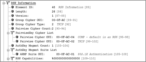
RSN Information Element
Within a BSS, how can client stations and an access point notify each other about their RSN capabilities? RSN security can be identified by a field found in certain 802.11 management frames. This field is known as the robust security network information element (RSNIE) and is often referred to simply as the RSN information element. An information element is an optional field of variable length that can be found in 802.11 management frames. The RSN information element can identify the encryption capabilities of each station. The RSN information element will also indicate whether 802.1X/EAP authentication or preshared key (PSK) authentication is being used.
The RSN information element field is found in four different 802.11 management frames: beacon management frames, probe response frames, association request frames, and reassociation request frames. Within a basic service set, an access point and client stations use the RSN information element within these four management frames to communicate with each other about their security capabilities prior to establishing association. As shown in Figure 9-17, access points will use beacons and probe response frames to inform client stations of the AP security capabilities.
Figure 9-17: Access point RSN security capabilities
As you can see in Figure 9-18, client stations use the association request frame to inform the access point of the client station security capabilities. When stations roam from one access point to another access point, they use the reassociation request frame to inform the new access point of the roaming client station’s security capabilities. The security capabilities include supported encryption cipher suites and supported authentication methods.
All 802.11 radios will use one cipher suite for unicast encryption and another cipher suite for encrypting multicast and broadcast traffic. Pairwise unicast encryption keys are created that are unique between two stations—the AP and a single client station. The pairwise cipher suite of the RSN information element contains the cipher suite information used by stations for unicast traffic. The cipher suite selector 00-0F-AC-04 (CCMP) is the default cipher suite value. The cipher suite selector 00-0F-AC-02 (TKIP) is optional. A group key is also created that is shared by all stations for broadcast and multicast traffic. The Group Cipher Suite field of the RSN information element contains the cipher suite information used by the BSS to protect broadcast/multicast traffic.
Figure 9-18: Client station RSN security capabilities
Figure 9-19 shows a capture of a beacon frame from an access point configured to use only CCMP/AES encryption. The RSN information element indicates that CCMP/AES encryption is being used for both the group cipher suite and the pairwise cipher suite. The access point is using the RSN information element to inform all client stations that the AP will be using CCMP encryption for all broadcast/multicast and will also be using CCMP/AES encryption for any unicast traffic. Any client station must support those exact ciphers for the client stations to be able to establish a robust secure network association (RSNA) with the AP and to create dynamic encryption keys. In other words, the client stations must support CCMP/AES encryption to be allowed to join the AP’s basic service set.
Figure 9-19: RSN Information element—CCMP pairwise and CCMP group cipher
Figure 9-20 shows a beacon frame from an access point configured to support both CCMP/AES and TKIP/RC4 encryption. The RSN information element indicates that TKIP encryption is being used for the group cipher suite. CCMP/AES is the default cipher for the pairwise cipher suite. The access point is using the RSN information element to inform all client stations that the AP will support either CCMP/AES or TKIP/RC4 encryption for any unicast traffic. However, only TKIP/RC4 encryption can be used for broadcast/multicast traffic. In this situation, the client stations must support either CCMP or TKIP to be allowed to join the AP’s basic service set. Because all the stations share a single group encryption key for broadcast and multicast traffic, the lowest common denominator must be used for the group cipher. In this case, the group cipher is TKIP.
Figure 9-20: RSN information element—CCMP pairwise and TKIP group cipher
The cipher suite selectors 00-0F-AC-01 (WEP-40) and 00-0F-AC-05 (WEP-104) are used as a group cipher suite in a transition security network (TSN) to allow pre-RSNA devices to join a BSS. For example, an access point might support CCMP, TKIP, and WEP encryption. WPA2-capable clients will use CCMP encryption for unicast traffic between the client STA and the AP. WPA capable clients will use TKIP encryption for unicast traffic between the client STAs and the AP. Legacy clients will use WEP encryption for unicast traffic between the client STAs and the AP. All the clients will use WEP encryption for the broadcast and multicast traffic. Because all the stations share a single group encryption key for broadcast and multicast traffic, the lowest common denominator must be used for the group cipher. In the case of a TSN, the group cipher is WEP.
Figure 9-21 shows a capture of a beacon frame from an access point configured to support CCMP/AES, TKIP/RC4, or static WEP encryption using a 40-bit static key. The RSN information element indicates that WEP-40 encryption is being used for the group cipher suite. CCMP/AES is the default cipher for the pairwise cipher suite. The access point is using the RSN information element to inform all client stations that the AP can support CCMP/AES, TKIP/RC4 encryption, or WEP-40 for any unicast traffic. However, only WEP-40 encryption can be used for broadcast/multicast traffic. In this situation, the client stations can support CCMP/AES, TKIP, or WEP-40 and be allowed to join the AP’s basic service set.
Figure 9-21: RSN information element—CCMP pairwise and WEP-40 group cipher
The RSN information element can also be used to indicate what authentication methods are supported. The authentication key management (AKM) suite field in the RSN information element indicates whether the station supports either 802.1X authentication or PSK authentication. If the AKM suite value is 00-0F-AC-01, authentication is negotiated over an 802.1X infrastructure using an EAP protocol. If the AKM suite value is 00-0F-AC-02 (PSK), then PSK is the authentication method being used.
Figure 9-22 shows a capture of an association request frame from a client station configured to 802.1X/EAP. The AKM suite field in the RSN information element indicates that 802.1X is the chosen authentication method.
Figure 9-22: RSN information element—AKM suite field: 802.1X
The IEEE 802.1X-2004 standard is not specifically a wireless standard and is often mistakenly referred to as 802.11x. The 802.1X standard is a port-based access control standard. 802.1X provides an authorization framework that allows or disallows traffic to pass through a port and thereby access network resources. An 802.1X framework may be implemented in either a wireless or wired environment. The 802.1X authorization framework consists of three main components, each with a specific role. These three 802.1X components work together to make sure only properly validated users and devices are authorized to access network resources. The layer 2 authentication protocol called Extensible Authentication Protocol (EAP) is used within the 802.1X framework to validate users at layer 2. The three major components of an 802.1X framework are as follows:
Supplicant A host with software that is requesting authentication and access to network resources. Each supplicant has unique authentication credentials that are verified by the authentication server. In a WLAN, the supplicant is often the laptop or wireless handheld device trying to access the network.
Authenticator A device that blocks or allows traffic to pass through its port entity. Authentication traffic is normally allowed to pass through the authenticator, while all other traffic is blocked until the identity of the supplicant has been verified. The authenticator maintains two virtual ports: an uncontrolled port and a controlled port. The uncontrolled port is used for EAP traffic, and the controlled port is used for all other traffic. Initially, the uncontrolled port is the only port that is open and passing traffic. A successful 802.1X authentication will trigger the controller port to be opened, allowing other traffic to traverse the network. In a WLAN, the authenticator is usually either an AP or a WLAN controller.
Authentication Server A server that validates the credentials of the supplicant that is requesting access and notifies the authenticator that the supplicant has been authorized. The authentication server will maintain a user database or may proxy with one or more external user databases to authenticate supplicant credentials.
You will see this terminology repeatedly over the course of your reading and hands-on work in WLAN security both inside this study guide and throughout industry publications. Each of these 802.1X components will now be briefly discussed in the sections that follow.
Supplicant
The supplicant is the device that will need to be validated by the authentication server before being allowed access to network resources. The supplicant will use an EAP protocol to communicate with the authentication server at layer 2. The supplicant will not be allowed to communicate at the upper layers of 3–7 until the supplicant’s identity has been validated at layer 2 by the authentication server
Think of the supplicant as the client software on a Wi-Fi device where the WLAN client security is configured. This is not to be confused with the driver for the 802.11 radio of the device. The supplicant is a software application that performs the 802.1X endpoint services on a client device such as a laptop. Fully featured enterprise supplicants can offer support for the wired Ethernet adapter and perhaps multiple 802.11 network adapters if necessary.
Authenticator
From the context of EAP authentication, the role of the authenticator is quite simple. The authenticator plays the role of the intermediary, passing messages between the supplicant and the authentication server. These messages travel via an EAP authentication protocol. Remember that authenticator is an 802.1X term. Also remember that 802.1X was described as a port-based access control standard. 802.1X essentially blocks traffic until a successful Layer 2 authentication occurs. When 802.1X is implemented on a Wi-Fi network, EAP is the authentication method that is used. As mentioned earlier, the authenticator maintains two virtual ports: an uncontrolled port and a controlled port. The uncontrolled port allows EAP authentication traffic to pass through, while the controlled port blocks all other traffic until the supplicant has been authenticated.
As shown in Figure 9-23, the authenticator is the AP when an autonomous access point solution is deployed, and the authentication server is typically a RADIUS server. Figure 9-23 also shows that when an 802.1X security solution is used with a WLAN controller solution, the WLAN controller is the authenticator—and not the controller-based access points.
Figure 9-23: 802.1X comparison-autonomous access point and WLAN controller
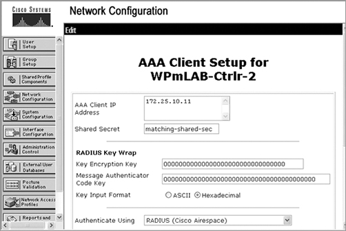
The term authenticator is a misnomer because the authenticator does not validate the supplicant’s credentials. The authenticator’s job is simply to let traffic either pass through or not pass through. What the authenticator needs to know is essentially who is going to provide the guest list services, which is the role of the authentication server. Therefore, when configuring a WLAN controller or AP as an authenticator, you would need to be able to point the authenticator in the direction of an authentication server. As shown in Figure 9-24, the authenticator would need to be configured with the RADIUS server’s IP address and UDP port along with a shared secret in order to communicate with the server. The shared secret is only for the authenticator-to-authentication server communication link. It should also be noted that the authenticator will be configured to “require” EAP authentication, but a specific EAP type is not chosen. Remember that the authenticator is essentially a pass-through device that either allows or disallows traffic to flow through the authenticator’s virtual ports.
Figure 9-24: Authenticator configuration

Authentication Server
The authentication server (AS) validates the credentials of a supplicant that is requesting access and notifies the authenticator that the supplicant has been authorized. The authentication server will maintain a user database or may proxy with an external user database to authenticate user credentials. The authentication server and the supplicant communicate using a layer 2 EAP authentication protocol.
The 802.1X standard defines the authentication server as a RADIUS server. Although RADIUS is what is officially defined in the standard, EAP is flexible, allowing other authentication servers such as a Lightweight Directory Access Protocol (LDAP)–compliant database to be used for authentication.
When configuring a RADIUS server, you need to be able to point the authentication server back in the direction of the authenticator. Typically the authenticator is a WLAN controller or autonomous AP. As shown in Figure 9-25, the AS would need to be configured with the authenticator’s IP address and shared secret in order to communicate with the authenticator.
Figure 9-25: Authentication server configuration
Configuration Gotchas
When configuring authenticators (APs or WLAN controllers) and RADIUS servers, there are usually two configuration problems that people regularly encounter: nonmatching shared secrets and wrong UDP ports. Ensure these values are correct before attempting any supplicant authentication attempts. RADIUS uses UDP ports 1812 for RADIUS authentication and 1813 for RADIUS accounting. These ports were officially assigned by the Internet Assigned Number Authority (IANA). However, prior to IANA allocation of UDP ports 1812 and 1813, the UDP ports of 1645 and 1646 (authentication and accounting, respectively) were used as the default ports by many RADIUS server vendors.
Extensible Authentication Protocol (EAP), as defined in IETF RFC 2284, provides support for many authentication methods. EAP was originally adopted for use with PPP. EAP has since been redefined in the IETF RFC 3748 for use with 802.1X port-based access control.
As noted earlier, EAP stands for Extensible Authentication Protocol. The key word in EAP is extensible. EAP is a layer 2 protocol that is very flexible, and many different flavors of EAP exist. Some are proprietary, while others are considered standards based. Some may provide for only one-way authentication, while others provide two-way authentication more commonly called mutual authentication. Mutual authentication not only requires that the authentication server validate the client credentials but also that the supplicant authenticate the validity of the authentication server. Most types of EAP that require mutual authentication use a server-side digital certificate to validate the authentication server.
As you learned earlier in this chapter, 802.1X is an authorization framework with the three components of the supplicant, authenticator, and authentication server. The main purpose of an 802.1X solution is to authorize the supplicant to use network resources. The supplicant will not be allowed to communicate at the upper layers of 3–7 until the supplicant’s identity has been validated at layer 2. EAP is the layer 2 protocol used within an 802.1X framework.
As mentioned earlier, the EAP messages are encapsulated in EAP over LAN (EAPOL) frames. EAPOL is used between the supplicant and the authenticator, but the EAPOL encapsulation is translated to EAP in RADIUS between the authenticator and the authentication server. There are five major types of EAPOL messages, as shown in Table 9-1.
Let’s review a generic EAP exchange. The two workhorses are the supplicant and the authentication server because they both use the EAP protocol to communicate with each other at layer 2. The authenticator sits between the two devices. As you have already learned, the authenticator maintains two virtual ports: an uncontrolled port and a controlled port. When open, the uncontrolled port allows EAP authentication traffic to pass through. The controlled port blocks all other traffic until the supplicant has been authenticated. When the controlled port is open, upper layers 3–7 traffic can pass through. Dynamic IP addressing with DHCP is performed once the controlled port is opened.
As shown in Figure 9-26, 802.1X/EAP authentication works together with standard 802.11 Open System authentication and association. An 802.11 client station will actually establish a layer 2 connection with the AP by associating and joining the basic service set. However, if 802.1X/EAP is implemented, layer 2 is as far as the 802.11 station gets until the client also goes through the entire 802.1X/EAP process.
Table 9-1: EAPOL messages
| Packet type | Name | Description |
| 0000 0000 | EAP-Packet | This is an encapsulated EAP frame. The majority of EAP frames are EAP-Packet frames. |
| 0000 0001 | EAPOL-Start | This is an optional frame that the supplicant can use to start the EAP process. |
| 0000 0010 | EAPOL-Logoff | This frame terminates an EAP session and shuts down the virtual ports. Hackers sometimes use this frame for DoS attacks. |
| 0000 0011 | EAPOL-Key | This frame is used to exchange dynamic keying information. For example, it is used during the 4-Way Handshake. |
| 0000 0100 | EAPOL- Encapsulated - ASF-Alert | This frame is used to send alerts, such as SNMP traps to the virtual ports. |
Figure 9-26: 802.11 association and 802.1X/EAP

Figure 9-27 displays all the steps in a generic EAP exchange. The authenticator in this example is an autonomous AP. Please refer to the figure as you read each step.
Figure 9-27: Generic EAP exchange
1. The 802.11 client (supplicant) associates with the AP and joins the BSS. Both the controlled and uncontrolled ports are blocked on the authenticator.
2. The supplicant initiates the EAP authentication process by sending an 802.11 EAPOL-Start frame to the authenticator. This is an optional frame and may or may not be used by different types of EAP.
3. The authenticator sends an 802.11 EAP-Request frame requesting the identity of the supplicant. The EAP-Request Identity frame is always a required frame.
4. The supplicant sends an EAP response frame with the supplicant’s identity in clear text. The username is always in clear text in the EAP-Response Identity frame. At this point, the uncontrolled port opens to allow EAP traffic through. All other traffic remains blocked by the controlled port.
5. The authenticator encapsulates the EAP response frame in a RADIUS packet and forwards it to the authentication server.
6. The AS looks at the supplicant’s name and checks the database of users and passwords. The AS will then send a password challenge to the supplicant encapsulated in a RADIUS packet.
7. The authenticator forwards the password challenge to the supplicant in an 802.11 EAP frame.
8. The supplicant takes the password and hashes it with a hash algorithm such as MD-5 or MS-CHAPv2. The supplicant then sends the hash response in an EAP from back to the AS.
9. The authenticator forwards the challenge response in a RADIUS packet to the AS.
10. The AS runs an identical hash and checks to see whether the response is correct. The AS will then send either a success or failure message back to the supplicant.
11. The authenticator forwards the AS message to the supplicant in an EAP-Success frame. The supplicant has now been authenticated.
12. The final step is the 4-Way Handshake negotiation between the authenticator and the supplicant. This is a complex process used to generate dynamic encryption keys. This process is discussed in great detail in Chapter 5.
13. Once the supplicant has completed layer 2 EAP authentication and created dynamic encryption keys, the controlled port is unblocked. The supplicant is then authorized to use network resources. If using IP, the next step the supplicant will take is to obtain an IP address either statically or by using DHCP.
You should notice that in step 4 the supplicant’s username is seen in clear text. You might say that is a security risk—and you would be correct. You should also notice that in steps 6–9, the supplicant’s password credentials are validated using a weak challenge/hash response. This frame exchange can be captured using a WLAN protocol analyzer. This is a security risk because the hash algorithms have been cracked and they are susceptible to offline dictionary attacks. In other words, the presentation of supplicant identity and validation of supplicant credentials is a security risk. Wouldn’t it be better if steps 4–9 were protected in an encrypted tunnel? Since its original adoption, a number of weaknesses were discovered with some EAP authentication methods. The most secure EAP methods used today employ tunneled authentication to pass identity credentials (usernames and passwords) similar to what you find with web-based ecommerce transactions.
We will now discuss the more commonly used strong EAP protocols that typically use tunneled authentication.
Strong EAP Protocols
The stronger and more commonly deployed methods of EAP use Transport Layer Security (TLS)–based authentication and/or TLS-tunneled authentication. In this section, we will cover some of these EAP types and their inner workings in detail.
Unlike some of the weaker EAP types, such as EAP-MD5 and EAP-LEAP, which have only one supplicant identity, EAP methods that use tunneled authentication have two supplicant identities. These two supplicant identities are often called the outer identity and inner identity. The outer identity is effectively a bogus username, and the inner identity is the true identity of the supplicant. The outer identity is seen in clear text outside the encrypted TLS tunnel, while the inner identity is protected within the TLS tunnel.
As you can see in Figure 9-28, the original EAP standard requires that there always be a clear-text value in the initial EAP-Response frame sent by the supplicant to the authentication server. This clear-text value is the outer identity that travels outside the TLS tunnel. The default value used by most supplicants is “anonymous.”
Figure 9-28: Outer identity
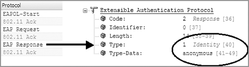
Although the default value used by most supplicants for the outer identity is “anonymous,” the outer identity is usually a configurable setting. Keep in mind that this is not the real username. Some WLAN administrators use funny names such as Donald Duck or Mickey Mouse. Other WLAN administrators use a facility code identifying a group of supplicants. The facility code could be used for troubleshooting efforts of 802.1X supplicant failures and can help you quickly narrow down the facility where the problem is occurring. Other WLAN administrators use the outer identity as a social engineering honeypot.
Do not confuse the encryption used by the TLS tunnel with layer 2 encryption that is used to protect the payload of 802.11 data frames. The encrypted TLS tunnel is created and exists only for a few milliseconds. The whole purpose of tunneled authentication is to provide a secure channel to protect the user identity credentials. The user credentials are encrypted inside the TLS tunnel. The TLS tunnel is not used to encrypt 802.11 data frames. We will now discuss versions of EAP that support tunneled authentication.
Tunnelled EAP and a Social Engineering Honeypot
In computer terminology, a honeypot is a trap set for potential hackers to detect and possibly counteract unauthorized access of a computer network. EAP methods, such as EAP-PEAP or EAP-TTLS, that use tunnelled authentication will always have an outer identity that can be seen in clear text with a WLAN protocol analyzer. A common strategy is to set a social engineering honeypot using the outer identity. The WLAN administrator configures all the company’s supplicants with the same value for the outer identity. The value could be Jane Barrett, when there is no user by that name who works at the company. Employees at the company are trained to alert security if anyone ever inquires about an employee named Jane Barrett. If someone inquires about the imaginary Jane Barrett, a social engineering attack is occurring and can be further investigated.
EAP-PEAP
EAP-Protected Extensible Authentication Protocol (EAP-PEAP), also known simply as PEAP, creates an encrypted TLS tunnel within which the supplicant’s inner identity is validated. Thus, the term protected is used because the supplicant’s identity and credentials are always encrypted inside the TLS tunnel that is established.
PEAP is probably the most common and most widely supported EAP method used in WLAN security. That is, it is the most popular EAP type that is considered highly secure. The confusion regarding PEAP usually revolves around the fact that there are multiple flavors of PEAP, including these three major versions:
- EAP-PEAPv0 (EAP-MSCHAPv2)
- EAP-PEAPv0 (EAP-TLS)
- EAP-PEAPv1 (EAP-GTC)
PEAP is often referred to as “EAP inside EAP” authentication because the inner authentication protocol used inside the TLS tunnel is also another type of EAP. PEAPv0 and PEAPv1 both refer to the outer authentication method and are the mechanisms that create the secure TLS tunnel to protect subsequent authentication transactions. The EAP protocol enclosed within parentheses is the inner EAP protocol used with each of these three flavors of EAP-PEAP. The main difference between these three major flavors of EAP is simply the inner EAP protocol that is used within the TLS tunnel.
Let’s discuss how all flavors of PEAP operate. A key point is that in order to establish the TLS tunnel, a server-side certificate is required for all flavors of PEAP. As shown in Figure 9-29, the EAP-PEAP process involves two phases. Please refer to the figure as we discuss the two phases of EAP-PEAP. We will use EAP-PEAPv0 (EAP-MSCHAPv2), as shown in Figure 9-29.
Phase 1
This first phase of EAP-PEAP establishes a secure tunnel using EAP-TTLS with server authentication.
1. The authenticator sends an EAP frame requesting the identity of the supplicant.
2. The supplicant responds with an EAP response frame with the clear-text outer identity that is not the real username and is a bogus username.
3. At this point, the uncontrolled port opens on the authenticator to allow EAP traffic through. All other traffic remains blocked by the controlled port. The authenticator forwards the outer identity response to the AS.
4. The outer identity response cannot inform the AS about the actual identity of the supplicant. It simply informs the AS that a supplicant wants to be validated.
5. The AS sends the server certificate down to the supplicant. The supplicant validates the server-side certificate and therefore authenticates the authentication server.
6. An encrypted point-to-point TLS tunnel is created between the supplicant and the authentication server. Once the TLS tunnel is established, Phase 2 can begin.
Figure 9-29: EAP-PEAP process
Phase 2
The second phase of EAP-PEAP implements the client authentication process.
1. The AS requests the real identity of the supplicant.
2. The supplicant responds with the inner identity, which is the real username. The real username is now hidden because it is encrypted inside the TLS tunnel.
3. The remaining steps in Phase 2 involve a password challenge from the AS and a hashed response from the supplicant using an authentication protocol within the tunnel. The supplicant credentials are validated by the authentication server. The entire exchange is encrypted within the TLS tunnel.
The whole point of Phase 2 is to validate the supplicant credentials while encrypted within the TLS tunnel. The inner identity, or real username, is protected and therefore hidden. Whatever authentication method is used inside the tunnel is also protected; therefore, any offline dictionary attacks are ineffective in obtaining the password.
PEAP has an interesting history. It began as a joint proposal by Cisco, Microsoft, and RSA Security. It was reported that Microsoft and Cisco did not completely agree on every detail, and subsequently Microsoft implemented PEAPv0 using MS-CHAPv2 as the inner authentication method. MS-CHAPv2 is Microsoft’s own version of CHAP. Because Microsoft is the dominant player in both client and server operating systems providing built-in support, this has led to the success of EAP-PEAPv0 (EAP-MS-CHAPv2). Cisco split from the original specification and created PEAPv1, which predominantly uses EAP-GTC as the inner authentication method.
PEAP is often referred to as “EAP inside EAP” authentication because the inner authentication protocol used inside the TLS tunnel is also another type of EAP. The only real difference is the inner EAP protocol that is used within the TLS tunnel. PEAPv0 and PEAPv1 both refer to the outer authentication method and are the mechanisms that create the secure TLS tunnel to protect subsequent authentication transactions. PEAPv0 supports inner EAP methods of EAP-MSCHAPv2 and EAP-TLS while PEAPv1 supports the inner EAP method of EAP-GTC. All versions of PEAP require a server-side certificate, and all versions of PEAP operate using the two phases described earlier.
Exercise 9-4
802.1X/EAP Frame Exchanges
In this exercise, you will use a protocol analyzer to view the 802.11 frame exchanges used during an 802.1X/EAP authentication process. The following directions should assist you with locating, downloading, and installing Wireshark. If you are familiar with another protocol analyzing software, feel free to use it to perform this lab. If you have already installed Wireshark, you can skip steps 1–4.
1. In your web browser, go to the Wireshark website: www.wireshark.org.
2. Click the Download Wireshark button to locate the installation file, and download the file that is appropriate for your operating system.
3. After downloading the file, double-click it to proceed with the installation, and follow the installation directions.
The exercise will use frame captures that are on the book’s companion CD. If you would like to use Wireshark for live wireless captures (and you are running Windows), you will have to purchase an AirPcap adapter from Cace Technologies (www.cacetech.com).
4. In Windows, choose Start All Programs, and then click the Wireshark icon. The Wireshark application should appear.
5. In the center section, click the Open icon, and browse to the book’s CD.
6. Open the packet capture file called EAP_MD5.PCAP.
The file will open and Wireshark will display three sections:
- The top section is called the packet list, displaying a list of the individual packets.
- The middle section is called the packet detail, displaying as much detail about each packet as possible.
- The bottom section shows the bytes in the current packet.
7. In the packet list, scroll down so that you can see packets 15–25. These packets are using EPA-MD5. Notice that there is only one EAPOL-key frame. This is because EAP-MD5 uses one-way authentication and dynamic encryption keys are not created. Notice in frames 7–13 that Open System authentication and association occurs prior to the EAP exchange.
8. Select packet 15 to observe the frame details. Notice that this is an EAPOL-Start frame.
9. Select packet 17 to observe the frame details. In the details section, scroll down to the 802.1X Authentication field. Observe that the packet type is an EAP packet.
10. Go to the File menu, and select Close. This will bring you back to the initial Wireshark screen.
11. In the center section, click the Open icon, and browse to the book’s CD.
12. Open the packet capture file called EAP_LEAP.PCAP.
13. Select packet 7 to observe the frame details. Notice that this is an EAP-Response frame. If you scroll down to the Extensible Authentication Protocol section, you will see the identity is airspy. The real username is always seen in clear text when LEAP is used.
14. Go to the File menu, and select Close. This will bring you back to the initial Wireshark screen.
15. In the center section, click the Open icon, and browse to the book’s CD.
16. Open the packet capture file called EAP_PEAP.PCAP.
17. Select packet 13. Scroll down to the field called Extensible Authentication Protocol. Observe that this is a response frame and that the identity is administrator. This is the outer identity that is always seen in clear text when PEAP is used. This is a bogus username. The real username is hidden inside the encrypted TLS tunnel.
18. Scroll down to display packets 47–53. These are the frames used to create dynamic encryption keys following the authentication process. Once the supplicant gets validated and the keys are created, the controlled port becomes unblocked.
19. Go to the File menu, and select Close.
20. In the center section, click the Open File icon, and browse to the book’s CD.
21. Open the packet capture file called EAP_TTLS.PCAP. Observe the EAP-TTLS frame exchange. Notice the similarity to PEAP.
22. Go to the File menu, and select Close.
23. In the center section, click the Open File icon, and browse to the book’s CD.
24. Open the packet capture file called EAP_TTLS.PCAP. Observe the EAP-TLS frame exchange.
The 802.11-2007 standard requires EAPOL-Key frames be used to exchange cryptographic information between the client STA supplicants and the authenticator, which is usually an access point. EAPOL-Key frames are used for the implementation of three different frame exchanges:
- 4-Way Handshake
- Group Key Handshake
- PeerKey Handshake
The 4-Way Handshake is a final process used to generate pairwise transient keys for encryption of unicast transmissions and a group temporal key for encryption of broadcast/multicast transmissions.
The 4-Way Handshake uses four EAPOL-Key frame messages between the authenticator and the supplicant for six major purposes:
- Confirm the existence of the PMK at the peer station
- Ensure that the PMK is current
- Derive a new pairwise transient key from the PMK
- Install the PTK on the supplicant and the authenticator
- Transfer the GTK from the authenticator to the supplicant and install the GTK on the supplicant and, if necessary, the authenticator
- Confirm the selection of the cipher suites
802.1X/EAP authentication is completed when the access point sends an EAP-Success frame and the AP can now initiate the 4-Way Handshake. Keep in mind that the authentication process has already generated the master keys (PMK and GMK), which will be used by the 4-Way Handshake to derive the temporal keys.
Before we explain the 4-Way Handshake process, it is necessary to define several key terms. The 4-Way Handshake uses pseudorandom functions. A pseudorandom function (PRF) hashes various inputs to derive a pseudorandom value. The PMK is one of the inputs combined with other inputs to create the pairwise transient key. Some of the other inputs used by the pseudorandom function are called nonces. A nonce is a random numerical value that is generated one time only. A nonce is used in cryptographic operations and is associated with a given cryptographic key. In the case of the 4-Way Handshake, a nonce is associated with the PMK. A nonce is used only once and is never used again with the PMK. Two nonces are created by the 4-Way Handshake: the authenticator nonce (ANonce) and the supplicant nonce (SNonce).
To create the pairwise transient key, the 4-Way Handshake uses a pseudorandom function that combines the pairwise master key, a numerical authenticator nonce, a supplicant nonce, the authenticator’s MAC address (AA), and the supplicant’s MAC address (SPA).
The following is a simplified depiction of the formula used by the pseudorandom function (PRF) to derive a pairwise transient key:
PTK = PRF (PMK + ANonce + SNonce + AA + SPA)
As Figure 9-30 shows, the 4-Way Handshake consists of the following steps:
1. 4-Way Handshake Message 1
The authenticator and supplicant each randomly create their respective nonces. The authenticator sends an EAPOL-Key frame containing an ANonce to the supplicant. The supplicant now has all the necessary inputs for the pseudorandom function. The supplicant derives a PTK from the PMK, ANonce, SNonce, and MAC addresses. The supplicant is now in possession of a pairwise transient key that can be used to encrypt unicast traffic.
2. 4-Way Handshake Message 2
The supplicant sends an EAPOL-Key frame containing an SNonce to the authenticator. The authenticator now has all the necessary inputs for the pseudorandom function. The supplicant also sends its RSN information element capabilities to the authenticator and a message integrity code (MIC). The authenticator derives a PTK from the PMK, ANonce, SNonce, and MAC addresses. The authenticator also validates the MIC. The authenticator is now in possession of a pairwise transient key that can be used to encrypt unicast traffic.
Figure 9-30: The 4-Way Handshake

3. 4-Way Handshake Message 3
If necessary, the authenticator derives a GTK from the GMK. The authenticator sends an EAPOL-Key frame to the supplicant containing the ANonce, the authenticator’s RSN information element capabilities, and an MIC. The EAPOL-Key frame may also contain a message to the supplicant to install the temporal keys. Finally, the GTK will be delivered inside this unicast EAPOL-Key frame to the supplicant. The confidentiality of the GTK is protected because it will be encrypted with the PTK.
4. 4-Way Handshake Message 4
The supplicant sends the final EAPOL-Key frame to the authenticator to confirm that the temporal keys have been installed.
5. Controlled Port Unlocked
The virtual controlled port opens on the authenticator, and now, encrypted 802.11 data frames from the supplicant can pass through the authenticator and on to their final destination. All unicast traffic will now be encrypted with the PTK, and all multicast and broadcast traffic will now be encrypted with the GTK.
Exercise 9-5
The 4-Way Handshake
In this exercise, you will use a protocol analyzer to view the 4-Way Handshake EAPOL-Key frames that are used to generate the temporal keys used for encryption. The following directions should assist you with locating, downloading, and installing Wireshark. If you are familiar with another protocol analyzing software, feel free to use it to perform this lab. If you have already installed Wireshark, you can skip steps 1–4.
1. In your web browser, go to the Wireshark website: www.wireshark.org.
2. Click the Download Wireshark button to locate the installation file, and download the file that is appropriate for your operating system.
3. After downloading the file, double-click it to proceed with the installation, and follow the installation directions.
The exercise will use frame captures that are on the CD that came with this book. If you would like to use Wireshark for live wireless captures (and you are running Windows), you will have to purchase an AirPcap adapter from Cace Technologies (www.cacetech.com).
4. In Windows, choose Start All Programs, and then click the Wireshark icon. The Wireshark application should appear.
5. In the center section, click the Open icon, and browse to the book’s CD.
6. Open the packet capture file called 4WAY_HANDSHAKE.PCAP.
The file will open and Wireshark will display three sections:
- The top section is called the packet list, displaying a list of the individual packets.
- The middle section is called the packet detail, displaying as much detail about each packet as possible.
- The bottom section shows the bytes in the current packet. Observe the EAP-Success frame at packet 66.
At this point, 802.1X/EAP authentication is completed, and the AP can now initiate the 4-Way Handshake. The access point (authenticator) MAC address is 00:12:43:CB:0F:30. The client station (supplicant) MAC address is 00:40:96:A3:0C:45.
7. Observe the EAPOL-Key frames of the 4-Way Handshake in packets 68, 70, 72, and 74. Open the first EAPOL-Key frame in packet 68. Notice that the AP is sending the client station an ANonce.
8. Open the second EAPOL-Key frame in packet 70. Notice that the client station is sending the AP an SNonce, an RSN information element, and a MIC.
9. Open the third EAPOL-Key frame in packet 72. Notice the AP is sending the supplicant an MIC and instructions to install the temporal keys.
10. Open the fourth EAPOL-Key frame in packet 74. The supplicant is now sending a message to the authenticator that the temporal keys are installed.
The 802.11-2007 standard also defines a two-frame handshake that is used to distribute a new group temporal key to client stations that have already obtained a PTK and GTK in a previous 4-Way Handshake exchange. The Group Key Handshake is used only to issue a new group temporal key to client stations that have previously formed security associations. Effectively, the Group Key Handshake is identical to the last two frames of the 4-Way Handshake. Once again, the purpose of the Group Key Handshake is to deliver a new GTK to all client stations that already have an original GTK generated by an earlier 4-Way Handshake.
The authenticator can update the GTK for a number of reasons. For example, the authenticator may change the GTK on disassociation or deauthentication of a client station. WLAN vendors may also offer a configuration setting to trigger the creation of a new GTK based on a timed interval.
As shown in Figure 9-31, the Group Key Handshake consists of the following steps:
1. Group Key Handshake Message 1
The authenticator derives a new GTK from the GMK. The new GTK is sent in a unicast EAPOL-Key frame to the supplicant. The confidentiality of the new GTK is protected because it will be encrypted with the original PTK from the initial 4-Way Handshake. The authenticator also sends a message integrity code. The supplicant validates the MIC when it receives the EAPOL-Key frame. The supplicant decrypts and installs the new GTK.
2. Group Key Handshake Message 2
The supplicant sends an EAPOL-Key frame to the authenticator to confirm that the GTK has been installed. The supplicant also sends a message integrity code. The authenticator validates the MIC when it receives the EAPOL-Key frame.
Figure 9-31: The Group Key Handshake
Please do not confuse Group Key Handshake with the two EAPOL-Key frame exchange that is used to distribute dynamic WEP keys. Although both handshakes use a two EAPOL-Key frame exchange, each handshake has an entirely different purpose.
The recently ratified 802.11r-2008 amendment is known as the fast basic service set transition (FT) amendment. Think of the term fast BSS transition as the technical name for standardized fast secure roaming. The main difference between OKC and FT is that the 802.11r-2008 amendment fully defines the key hierarchy used when creating cached keys.
802.11r mechanisms can be used in an autonomous AP environment; however, an intelligent, or coordinated enterprise WLAN solution is best suited for an FT solution. Therefore, we will discuss 802.11r within the context of a WLAN controller architecture. 802.11r mechanisms operate within a mobility domain. A mobility domain is a set of basic service sets, within the same extended service set (ESS), that supports fast BSS transitions between themselves. In simpler words, a mobility domain is a group of APs that belong to the same ESS where client stations can roam in a fast and secure manner. Some WLAN vendors even refer to their WLAN controllers as the mobility domain controller (MDC). The first time a client station enters a mobility domain, the client will associate with an AP and perform an initial 802.1X authentication. From that point forward, as the client station roams between APs, the client will be using FT BSS transitions. FT BSS transition can be over-the-air or over-the-DS.
Information Elements
To achieve successful fast secure roaming, FT mechanisms require the use of the RSN information element to indicate the specific authentication key management (AKM) suites and pairwise cipher suites that are being used between the AP and the client station. The 802.11r-2008 amendment also adds four new information elements. However, we are going to focus on just two of them.
The mobility domain information element (MDIE) is used to indicate the existence of a mobility domain as well as the method of fast BSS transition. As shown in Figure 9-32, the mobility domain identifier (MDID) field is the unique identifier of the group of APs that constitute a mobility domain. The FT capability and policy field is used to indicate whether over-the-air or over-the-DS fast BSS transition is to be performed. We will discuss the difference between over-the-air and over-the-DS fast BSS transition later in this chapter.
Figure 9-32: Mobility domain information element
The fast BSS transition information element (FTIE) includes information needed to perform the FT authentication sequence during a fast BSS transition. As shown in Figure 9-33, some of the fields look very similar to the information used during a typical 4-Way Handshake exchange. In the next section, you will see how this information is used in a similar manner during the various FT processes.
Figure 9-33: Fast BSS transition information element

FT Initial Mobility Domain Association
The FT initial mobility domain association is the first association in the mobility domain. As shown in Figure 9-34, the client station first exchanges the standard 802.11 Open System authentication request/response frames with the first AP. The client station and AP then use the MDIE and FTIE information in the association request/response frames to indicate future use of the FT procedures. An original 802.1X/EAP exchange between the client station and the RADIUS server must then occur so seeding material is established for a FT 4-Way Handshake that occurs only during the first association. The PTK and GTK encryption keys are created during the FT 4-Way Handshake and the 802.1X controlled port is unblocked. The original 802.1X/EAP exchange also creates the master session key (MSK) that is used for the FT key hierarchy. As you can see, the FT initial mobility domain association is not much different from any initial association used by pre-802.11r clients. The main difference is that extra information, such as the MDIE and FTIE, is communicated during an FT initial mobility domain association.
Figure 9-34: FT initial mobility domain association
After the initial association, two new methods are defined for a client station to roam from the original AP to a target AP. We will now discuss these two methods of fast BSS transition.
Over-the-Air Fast BSS Transition
Let’s consider all the frames that need to be exchanged between a client station and an AP. First, a client has to exchange Open System authentication frames and association frames, as was shown in Figure 9-32. This is a total of four frames, not including the ACKs. Next, a successful 802.1X/EAP exchange between the supplicant and the RADIUS server is needed. The 802.1X/EAP exchange requires many frames. Finally, a 4-Way Handshake exchange is needed between the AP and the client station to create the final dynamic encryption keys. We already know that the purpose of FT and other fast secure roaming mechanisms is to eliminate the need for a new 802.1X/EAP frame exchange every time a client roams. However, the initial four frames of Open System authentication and reassociation are still needed as well as the four frames used during the 4-Way Handshake.
The FT process defines a more efficient method that effectively combines the initial Open System authentication and reassociation frames with the 4-Way Handshake frames. In other words, four less frames are needed when a client roams, thus speeding up the roaming process. As shown in Figure 9-33, an FT protocol frame exchange is used to initiate the roaming exchange and create dynamic encryption keys. Note that the authentication request/response frames and reassociation request/response frames carry an FT authentication algorithm (FTAA) along with nonces and other information needed to create the final dynamic keys. The process shown in Figure 9-35 is known as over-the-air fast BSS transition. The client station communicates directly with the target AP using standard 802.11 authentication with the FT authentication algorithm. The PMK-R1 key is the seeding material for the over-the-air fast BSS transition process that creates the final pairwise transient key.
Over-the-DS Fast BSS Transition
An alternative to the FT method is over-the-DS fast BSS transition, which requires the use of FT Action frames to complete the PTK creation process. The over-the-DS process uses the FT Action frames over the wired 802.3 infrastructure. As shown in Figure 9-36, the client station sends an FT Action request frame to the original AP. The FT Action request frame is forwarded over the distribution system (DS), which is the wired infrastructure. The target AP responds to the client station over the DS with an FT Action response frame. The reassociation request and response frames are then sent from the client station to the target AP over the air. The PMK-R1 key is the seeding material for the over-the-DS fast BSS transition exchange that creates the final pairwise transient key (PTK).
Figure 9-35: Over-the-air fast BSS transition
Figure 9-36: Over-the-DS fast BSS transition
Figure 9-37 shows the multiple steps of the complex fast BSS transition process that has been discussed in this chapter. The process begins with an initial mobility domain association and finally ends with creation of the pairwise transient keys needed for encryption and decryption.
Figure 9-37: 802.11r fast BSS transition summary
802.11w Protected Management Frames
The 802.11i amendment was created to provide robust security to wireless LANs; however, 802.11i was designed only to provide security for data frames. A common type of attack on an 802.11 WLAN is a denial-of-service attack (DoS attack). There are a multitude of DoS attacks that can be launched against a wireless network; however, a very common DoS attack occurs at layer 2 using spoofed 802.11 management frames. It is fairly simple for an attacker to edit deauthentication or disassociation frames and then retransmit the frames into the air and effectively shut down the wireless network.
The goal of the IEEE Task Group w (TGw) was to provide a way of delivering management frames in a secure manner, therefore preventing the management frames from being able to be spoofed. Figure 9-38 shows the RSN capabilities field format. Bit 6 is the Management Frame Protection Required (MFPR) bit, which an STA uses to advertise that it requires the use of protected management frames. Bit 7 is the Management Frame Protection Capable (MFPC) bit, which an STA uses to advertise that it is capable of using protected management frames but does not require them.
Figure 9-38: RSN capabilities field format
802.11w provides protection for unicast, broadcast, and multicast management frames. These 802.11w frames are referred to as robust management frames. Robust management frames can be protected by the management frame protection service and include disassociation, deauthentication, and robust action frames. Action frames are used to request a station to take action on behalf of another station, and not all action frames are robust.
When unicast management frames are protected, frame protection is achieved by using CCMP. Broadcast and multicast frames are protected using broadcast/multicast integrity protocol (BIP). BIP provides data integrity and replay protection using AES-128 encryption in Cipher Based Message Authentication Code (CMAC) mode.
In this chapter, we discussed many of the different methods to provide wireless security. Different types of encryption were reviewed along with advanced wireless authentication methods. We also looked at many of the security frame formats and exchanges.
Understand 802.11 authentication. There are two types of 802.11 authentication: Open System and Shared Key. Know the differences between them along with the frame exchange that is used to establish each. Also understand why Shared Key authentication is considered to be less secure.
Know the WLAN encryption methods. Understand WLAN encryption and know the differences between WEP, TKIP, and CCMP. Know the different encryption processes along with how the frames are modified during these processes.
Explain WPA and WPA2. Explain the background of WPA and WPA2 along with their similarities and differences. Know how the Personal and Enterprise versions differ.
Define robust security network. Define what a robust security network is and how it provides security for both BSS and IBSS wireless networks. Understand its differences from a transition security network.
Understand RSN information elements. Understand how the RSN information element can identify the encryption capabilities of each station.
Explain 802.1X components. Explain the different components of an 802.1X network: supplicant, authenticator, and authentication server. Understand their relationship between each other and each of their roles.
Understand the function of EAP. Understand the EAP process from a basic overview to a more advanced and secure version such as EAP-PEAP.
Understand the 4-Way and Group Key handshake processes. Understand the communications processes involved with these handshake methods.
Know fast BSS transition. Know the 802.11r-2008 amendment defined FT, also known as fast secure roaming. Know how RSN information elements are used with it, along with the FT initial mobility domain association. Know how over-the-air fast BSS transition and over-the-DS fast BSS transition is performed.
Explain 802.11w protected management frames. Explain why 802.11w was created and how it achieves what it was designed to perform.
Before you take the exam, be certain you are familiar with the following terms:
4-Way Handshake
802.1X
associated
authentication server (AS)
authenticator
authenticator nonce (ANonce)
basic service set identifier (BSSID)
EAP-TLS
EAP-TTLS
Group Key Handshake
independent basic service set (IBSS)
Management Frame Protection Capable (MFPC)
Management Frame Protection Required (MFPR)
nonce
pre-robust security network associations (pre-RSNAs)
pseudo-random function (PRF)
robust security network (RSN)
robust security network association (RSNA)
robust security network information element (RSNIE)
RSN information element
service set identifier (SSID)
supplicant nonce (SNonce)
The basic service set (BSS)
transition security network (TSN)
Transport Layer Security (TLS)
Wi-Fi Protected Access (WPA)
1. Laura is attempting to diagnose a WLAN by using a packet analyzer to capture the exchange of frames and packets between a wireless client and the AP. In the process of analyzing the packets, she sees two 802.11 authentication frames, two 802.11 association frames, and DHCP requests and responses, and then she begins to see encrypted data. Which of the following could the client be using? (Choose all that apply.)
A. Open System authentication
B. Shared Key authentication
C. 802.1X/EAP
D. WEP
E. PPTP
F. L2TP/IPsec
2. This graphic shows a packet capture of a successful 802.11 authentication. In which of the following types of client connections could this authentication not occur? (Choose all that apply.)
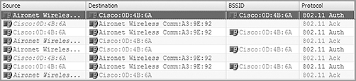
A. 802.1X/EAP
B. VPN
C. WEP with Shared Key authentication
D. WEP with Open System authentication
E. Open System authentication with WEP
3. The graphic shows a packet capture of a successful 802.11 authentication. In which of the following types of client connections could this not occur?
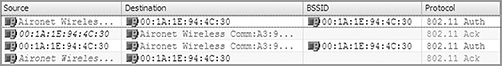
A. 802.1X/EAP
B. VPN
C. WEP with Shared Key authentication
D. WEP with Open System authentication
E. Unencrypted
4. Given that CCMP uses a MIC for data integrity to protect the frame body and portions of the MAC header, what information needs to be constructed to protect certain fields in the MAC header?
A. Nonce
B. Extended IV
C. ICV
D. AAD
E. PN
F. IV
5. How many extra bytes of overhead does TKIP/RC4 encryption add to the body of an 802.11 MPDU?
A. 16 bytes
B. 12 bytes
C. 20 bytes
D. 10 bytes
E. None of the above
6. The TKIP MIC is used for data integrity. Which portions of an 802.11 MPDU does the TKIP MIC protect from being altered? (Choose all that apply.)
A. MSDU
B. SA
C. DA
D. TA
E. Frame Control field
F. MSDU priority bit
7. What does 802.1X/EAP provide when implemented for WLAN security? (Choose all that apply.)
A. Access to network resources
B. Verification of access point credentials
C. Dynamic authentication
D. Dynamic encryption-key generation
E. Verification of user credentials
8. View the frame capture of the 4-Way Handshake in the graphic shown here. Which EAPOL-Key message frame is displayed?
A. 4-Way Handshake message 1
B. 4-Way Handshake message 2
C. 4-Way Handshake message 3
D. 4-Way Handshake message 4
9. What are some of the frames that carry the security capabilities found in the RSN information element? (Choose all that apply.)
A. Beacon management frame
B. Probe request frame
C. Probe response frame
D. Association request frame
E. EAPOL-Key frame
F. Request-to-Send frame
10. In a robust security network (RSN), which 802.11 management frames are used by client stations to inform an access point about the RSNA security capabilities of the client STAs? (Choose all that apply.)
A. Beacon management frame
B. Probe request frame
C. Probe response frame
D. Association request frame
E. Reassociation response frame
F. Reassociation request frame
G. Association response frame
11. After viewing the frame capture shown here, identify the type of authentication method being used.
A. EAP-TTLS
B. Open System
C. PSK
D. EAP-TLS
E. PEAP
12. Which of these roaming methods requires the use of FT Action frames?
A. Over-the-air fast BSS transition
B. Over-the-WDS fast BSS transition
C. Over-the-DS fast BSS transition
D. Over-the-WLS fast BSS transition
13. Before an 802.11 client STA can pass traffic through the AP, which two of the following must occur? (Choose two answers.)
A. 802.1X
B. EAP
C. Association
D. Authentication
E. WEP keys must match
14. How many extra bytes of overhead does CCMP/AES encryption add to the body of an 802.11 data frame?
A. 16 bytes
B. 12 bytes
C. 20 bytes
D. 10 bytes
E. None of the above
15. A data integrity check known as message integrity code (MIC) is used by which of the following? (Choose all that apply.)
A. WEP
B. TKIP
C. CCMP
D. AES
E. DES
16. How does a RADIUS server communicate with an authenticator? (Choose all that apply.)
A. UDP ports 1812 and 1813
B. TCP ports 1645 and 1646
C. Encrypted TLS tunnel
D. Encrypted IPsec tunnel
E. RADIUS IP packets
F. EAPOL frames
17. What must occur in order for dynamic TKIP/RC4 or CCMP/AES encryption keys to be generated? (Choose all that apply.)
A. Shared Key authentication and 4-Way Handshake
B. 802.1X/EAP authentication and 4-Way Handshake
C. Open System authentication and 3-Way Handshake
D. Open System authentication and 4-Way Handshake
E. 802.1X/EAP authentication and 3-Way Handshake
18. After viewing the frame capture in the graphic shown here, identify which type of security network is being used.
A. Robust Security Network
B. Rotund Security Network
C. Transition Security Network
D. WPA Security Network
E. WPA
19. 802.11w provides protection for which of the following types of frames? (Choose all that apply.)
A. Unicast
B. Broadcast
C. Anycast
D. Simulcast
E. Multicast
20. 802.11w Protected Management Frames was created to prevent which of the following types of attacks? (Choose all that apply.)
A. Denial of service
B. Deauthentication attack
C. Disassociation attack
D. Impersonation attack
E. Bit-flipping attack
1. A, E, F. Since there are only two 802.11 authentication frames, Open System authentication is being used. Shared Key authentication would generate four 802.11 authentication frames. If 802.1X/EAP or WEP were being used, then the client would be doing L2 encryption, and the DHCP frames would be encrypted and not visible. Therefore, 802.1X/EAP and WEP are not being used. Both PPTP and L2TP/IPsec perform layer 3 encryption that would allow Laura to see the DHCP exchange and any other IP traffic.
2. A, D, E. The graphic shows an 802.11 Shared Key authentication that consists of four authentication frames: an authentication request followed by a clear-text challenge frame, followed by a challenge response with the clear-text data encrypted, and then followed by an authentication response. 802.1X/EAP works together with Open System authentication but cannot be deployed when WEP is used. To use Shared Key authentication, WEP must be enabled. A VPN can be used with Shared Key or Open System authentication. Companies would use a VPN for data privacy because WEP has been cracked, but they often would still use WEP as an added layer of security. Shared Key authentication is optional with WEP, although not recommended.
3. C. The graphic shows a two-frame Open System authentication. 802.1X/EAP works together with Open System authentication. VPN can be configured with either Open System or Shared Key authentication. An unencrypted session uses Open System authentication.
4. D. Additional authentication data (AAD) is constructed from portions of the MPDU header. This information is used for data integrity of portions of the MAC header. Receiving stations can then validate the integrity of these MAC header fields. The MIC protects the AAD information and the frame body for data integrity.
5. C. When TKIP is implemented, because of the extra overhead from the extended IV and the MIC, a total of 20 bytes of overhead is added to the body of an 802.11 MPDU. CCMP/AES encryption will add an extra 16 bytes of overhead to the body of an 802.11 MPDU. WEP encryption will add an extra 8 bytes of overhead to the body of an 802.11 MPDU.
6. A, B, C. TKIP uses a stronger data integrity check known as the message integrity code (MIC) to mitigate known forgery attacks against WEP. The MIC is often referred to by its nickname of Michael. The MIC can be used to defeat bit-flipping attacks, fragmentation attacks, redirection, and impersonation attacks. The MIC is computed using the destination address (DA), source address (SA), MSDU Priority, and the entire unencrypted MSDU plaintext data. After the MIC is generated, it is appended to the end of the MSDU payload.
7. A, D, E. The purpose of 802.1X/EAP is authentication of user credentials and authorization to access network resources. Although the 802.1X framework does not require encryption, it highly suggests the use of encryption. A by-product of 802.1X/EAP is the generation and distribution of dynamic encryption keys. Although the encryption process is actually a byproduct of the authentication process, the goals of authentication and encryption are very different. Authentication provides mechanisms for validating user identity while encryption provides mechanisms for data privacy or confidentiality.
8. C. The third EAPOL-Key frame of the 4-Way Handshake may also contain a message to the supplicant to install the temporal keys. The frame capture indicates that the temporal key is to be installed. The third EAPOL-Key frame also sends the supplicant the ANonce, the authenticator’s RSN information element capabilities, and a MIC. If a GTK has been generated, the GTK will be inside the third EAPOL-Key frame. The GTK confidentiality is protected because it will be encrypted with the PTK.
9. A, C, D, E. The RSN information element field is found in four different 802.11 management frames: beacon management frames, probe response frames, association request frames, and reassociation request frames. The RSN information element can also be found in the second and third EAPOL-Key frames of the 4-Way Handshake.
10. D, F. The RSN information element field is found in four different 802.11 management frames: beacon management frames, probe response frames, association request frames, and reassociation request frames. Within a basic service set, an access point and client stations use the RSN information element within these four management frames to communicate with each other about their security capabilities prior to establishing association. Client stations use the association request frame to inform the access point of the client station security capabilities. When stations roam from one access point to another access point, they use the reassociation request frame to inform the new access point of the roaming client station’s security capabilities. The security capabilities include supported encryption cipher suites and supported authentication methods.
11. C. The RSN information element can also be used to indicate what authentication methods are supported. The authentication key management (AKM) suite field in the RSN information element indicates whether the station supports either 802.1X authentication or PSK authentication. If the AKM suite value is 00-0F-AC-01, authentication is negotiated over an 802.1X infrastructure using an EAP protocol. If the AKM suite value is 00-0F-AC-02, then PSK is the authentication method that is being used.
12. C. The pairwise transient key (PTK) is the third-level key of the FT key hierarchy. The PTK is the final key used to encrypt 802.11 data frames. The PTK is created during either an over-the-air fast BSS transition frame exchange or over-the-DS fast BSS transition frame exchange. In any 802.11 robust security network (RSN), the PTK is used to encrypt the MSDU payload of an 802.11 unicast data frame.
13. C, D. For a client to connect to the WLAN and pass data, the client must authenticate and associate. The other three choices could occur but do not have to do so.
14. A. CCMP/AES encryption will add an extra 16 bytes of overhead to the body of an 802.11 data frame. Eight bytes are added by the CCMP header and 8 bytes are added by the MIC. WEP encryption will add an extra 8 bytes of overhead to the body of an 802.11 data frame. When TKIP is implemented, because of the extra overhead from the extended IV and the MIC, a total of 20 bytes of overhead is added to the body of an 802.11 data frame.
15. B, C. A stronger data integrity check known as a message integrity code (MIC), or by its common name, Michael, was introduced with TKIP to correct some of the weaknesses in WEP. CCMP also uses a MIC. AES and DES are encryption algorithms and are not concerned with message integrity.
16. A, E. The RADIUS protocol uses UDP ports 1812 for RADIUS authentication and 1813 for RADIUS accounting. These ports were officially assigned by the Internet Assigned Number Authority (IANA). However, prior to IANA allocation of UDP ports 1812 and 1813, the UDP ports of 1645 and 1646 (authentication and accounting, respectively) were used as the default ports by many RADIUS server vendors. TCP is not used. All Layer 2 EAP traffic sent between the RADIUS server and the authenticator is encapsulated in RADIUS IP packets. The encrypted TLS tunnel communications are between the supplicant and the authentication server. IPsec is not used.
17. B, D. Open System and Shared Key authentication are legacy authentication methods that do not provide seeding material to generate dynamic encryption keys. However, a four-way Open System authentication must occur prior to the EAP exchange. A robust security network association requires a four-frame EAP exchange known as the 4-Way Handshake that is used to generate dynamic TKIP or CCMP keys.
18. C. The frame capture shows an RSN information element field that can be found in a management frame. The RSN information element shows that the group cipher that is being used is WEP. A transition security network (TSN) supports RSN-defined security as well as legacy security such as WEP within the same BSS. Within a TSN, some client stations will use RSNA security using TKIP/RC4 or CCMP/AES for encrypting unicast traffic. However, some legacy stations are still using static WEP keys for unicast encryption. All of the clients will use WEP encryption for the broadcast and multicast traffic. Because all the stations share a single group encryption key for broadcast and multicast traffic, the lowest common denominator must be used for the group cipher.
19. A, B, E. 802.11w provides protection for unicast, broadcast, and multicast management frames. These 802.11w frames are referred to as robust management frames. Anycast and simulcast frames do not exist.
20. A, B, C. 802.11w was developed to provide security for management frames. This prevents denial-of-service attacks, such as deauthentication attacks and disassociation attacks. It will not prevent bit-flipping attacks. Some impersonation attacks use denial of service prior to performing the impersonation; however, since some do not use DoS attacks, this answer is not always correct.