Chapter 10
802.11n HT Analysis
In this chapter, you will learn about the following:
- Introduction to 802.11n
- 802.11n Fields, Information Elements, and Frames
- HT Control Field
- HT Control Wrapper Frame
- HT Capabilities Element
- HT Operation Element
- Physical Layer Enhancements
- Spatial Multiplexing
- Transmit Beamforming
- Space Time Block Coding (STBC)
- Antenna Selection
- 40 MHz Channels
- Short Guard Interval
- Modulation and Coding Schemes (MCSs)
- MAC Layer Enhancements
- A-MSDU
- A-MPDU
- Delayed BlockAcks
- RIFS
- 802.11n Protection Mechanisms
- Mode 0 – Green Field
- Mode 1 – HT non-Member Protection
- Mode 2 – HT 20 MHz Protections
- Mode 3 – Non-HT Mixed Mode
- Dual CTS
- L-Sig TXOP Protection
- Phased Co-Existence Operation
- 40-MHz Intolerant
The 802.11n amendment Enhancements for Higher Throughput (HT) specifies a number of improvements to the 802.11 physical (PHY) layer and Medium Access Control (MAC) layer to support throughput of 100 Mbps or greater. With the promise of data rates up to 600 Mbps, increased range, and more robust connections, 802.11n HT technology is certainly an attractive prospect.
Many of the PHY layer enhancements are due to a new PHY layer technology called multiple-input multiple-output (MIMO), which utilizes multiple antennas and radios. The Physical layer enhancements are spatial multiplexing (SM), transmit beamforming (TxBF), space-time block coding (STBC), low-density parity check (LDPC), antenna selection (ASEL), and channel bonding (where throughput is increased by extending the channel width from 20 MHz to 40 MHz, effectively bonding two channels together as one).
Another PHY layer enhancement implemented by many MIMO access points is Maximal Ratio Combining (MRC). MRC processes the signals received on multiple antennas into one stronger signal. This is achieved through an advanced digital signal processing technique that brings all the receive signals in phase with each other and then combines them together into one signal. Although implemented by vendors, MRC is not defined in the 802.11n amendment and is not a technology that can be easily analyzed and therefore will not be discussed within this chapter.
For each 20 MHz and 40 MHz channel, the 802.11n amendment introduces 77 new modulation and coding schemes (MCSs). This, in turn, introduces a whole array of new data rates. Each MCS is given an index to provide easy reference. Two new PPDU headers are also defined, giving HT stations the choice of legacy non-HT format, HT mixed format, and HT Greenfield format.
MAC layer enhancements improve efficiency by reducing the overhead required for standard frame exchanges. The MAC layer enhancements are frame aggregation, block acknowledgments, power save multi-poll (PSMP), and Reverse Direction (RD) protocol. MAC layer protection mechanisms for supporting the coexistence with non-HT STAs are also introduced.
The number and combination of these 802.11n enhancements that a vendor decides to implement will govern the theoretical maximum data rate possible. Environmental conditions of an installed access point will then dictate the actual throughput achieved.
The 802.11n-2009 amendment is a 536-page document, and this chapter does not attempt to discuss all the details within its pages. This chapter will instead focus on the information that is of use when performing wireless network analyses. After an introduction to the 802.11n amendment, this chapter will focus on three main areas: the HT Control field, the HT Capabilities Element, and the HT Operation Element. Within these three elements and their associated frames are more than 100 fields and subfields to be discussed.
As we explore the wealth of information available to the wireless analyst in these three areas, we’ll also discuss the protocol exchanges and frames that support them. We will outline how the different enhancements affect wireless network analysis and what we can expect to see in a protocol analyzer.
As we take a ride through the 802.11n amendment looking at all the new frames, fields, and flags that are needed to support the vast array of enhancements, you must be prepared for some hard study.
Before we delve into the details of 802.11n wireless analysis, it is essential to have a general overview of the HT amendment. The 802.11n-2009 amendment was ratified on September 11, 2009, six years to the day after the IEEE-SA New Standards Committee approved the request to create the 802.11 Task Group n (TGn). This group was responsible for the development of the 802.11n amendment. The amendment is essentially a list of enhancements to the current 802.11 standard that answer the following question: “What can we do to improve the performance and throughput of current 802.11 wireless networks?” We get answers like the following: “If we transmit data over two channels instead of one, we can double our throughput.” “If we don’t have to acknowledge every data packet, we can make data transfer more efficient.” “If we reduce the amount of time we have to wait between sending packets, we increase our efficiency.”
This section will provide a high-level overview of the technologies defined by the 802.11n amendment. For CWNAs, this section should act as an 802.11n refresher, providing you with the prerequisite 802.11n knowledge required for the rest of this chapter. The different enhancements added by the 802.11n amendment will be defined in this section, and then you’ll look at the parts of the amendment that the Wi-Fi Alliance tests and certifies products against.
Frequency Spectrum
HT (clause 20) technology defined by the 802.11n amendment is backward compatible with existing HR-DSSS (clause 18), ERP (clause 19), and OFDM (clause 17) technology. Because HR-DSSS and ERP radios operate in the 2.4 GHz ISM band and OFDM radios operate in the 5 GHz UNII band, HT technology is not frequency dependant and can be used in both the 2.4 GHz and 5 GHz bands.
MIMO
The heart and soul of the 802.11n amendment exists at the PHY layer with the use of a technology known as multiple-input multiple-output (MIMO). MIMO requires the use of multiple radios and antennas, called radio chains. MIMO systems use multiple antennas to provide for better antenna diversity, which can increase range. Transmitting multiple streams of data with spatial multiplexing provides for greater throughput and takes advantage of the old enemy known as multipath. Transmit beamforming is an optional smart antenna technology that can be used in MIMO systems to “steer” beams and provide for greater range and throughput.
Radio Chains
Conventional 802.11 radios transmit and receive RF signals by using a single-input single-output (SISO) system. SISO systems use a single radio chain. A radio chain is defined as a single radio and all of its supporting architecture, including mixers, amplifiers, and analog/digital converters.
A MIMO system consists of multiple radio chains, with each radio chain having its own antenna. A MIMO system is characterized by the number of transmitters and receivers used by the multiple radio chains. For example, a 2×3 MIMO system would consist of three radio chains with two transmitters and three receivers. A 3×3 MIMO system would use three radio chains with three transmitters and three receivers. In a MIMO system, the first number always references the transmitters (TX), and the second number references the receivers (RX).
Figure 10-1 illustrates both 2×3 and 3×3 MIMO systems. Please note that both systems utilize three radio chains; however, the 3×3 system has three transmitters, whereas the 2×3 system has only two transmitters.
Figure 10-1: 2×3 and 3×3 MIMO

Using multiple transmitters in a MIMO system provides for the transmission of more data via spatial multiplexing. Using multiple receivers increases signal-to-noise ratio (SNR) because of advanced MIMO antenna diversity. The 802.11n standard allows for MIMO systems up to 4×4 using four radio chains. Each radio chain requires power. A 2×2 MIMO system would require much less of a power draw than a 4×4 MIMO system.
MIMO Enhancements
The enhancements provided by MIMO technology are summarized here:
Transmit Beamforming (TxBF) This is a method that allows a MIMO transmitter using multiple antennas to “focus” the transmissions in the best direction of a receiver (RX).
Spatial Multiplexing (SM) MIMO radios transmit multiple radio signals at the same time. Each independent signal is known as a spatial stream, and each unique stream can contain different data. SM increases our overall throughput.
Space-Time Block Coding (STBC) This is a method to improve the reliability of data transfer by transmitting different copies of the data stream from different antennas. This adds a level of redundancy to our data communication. By increasing the signal quality, the range is also increased.
Antenna Selection (ASEL) This is a method to increase signal diversity by dynamically selecting which antennas to use when a STA has more antennas than radio chains.
The details of how TxBF and ASEL work and their protocols will be discussed later in this chapter when exploring the fields of the HT Capabilities Element. TxBF operation will be explained in the section “Transmit Beamforming Capabilities,” and ASEL operation will be discussed in the section “ASEL Capabilities.” You can find more information on STBC in the section “HT Capabilities Element,” covering the TX STBC and RX STBC subfields, as well as the section “HT Operation Element,” covering dual beacons, dual CTS, and STBC beacons. A more detailed description of spatial multiplexing will be discussed next. Many of the topics in this chapter require you to have a basic understanding of SM. However, the basic operation of SM is not manifested in the packets and is therefore hard to analyze.
Spatial Multiplexing
In traditional 802.11 environments, the phenomenon of multipath has long caused problems. Multipath is a propagation phenomenon that results in two or more paths of the same signal arriving at a receiving antenna at the same time or within nanoseconds of each other. Because of the natural broadening of the waves, the propagation behaviors of reflection, scattering, diffraction, and refraction will occur. A signal may reflect off an object or may scatter, refract, or diffract. These propagation behaviors can each result in multiple paths of the same signal. The negative effects of multipath can include loss of amplitude and data corruption. 802.11n MIMO systems, however, take advantage of multipath, and, believe it or not, multipath then becomes our friend.
MIMO radios transmit multiple radio signals at the same time and take advantage of multipath. Each individual radio signal is transmitted by a unique radio and antenna of the MIMO system. Each independent signal is known as a spatial stream, and each unique stream can contain different data than the other streams transmitted by one or more of the other radios. Each stream will also travel a different path, because there is at least a half-wavelength of space between the multiple transmitting antennas. The fact that the multiple streams follow different paths to the receiver because of the space between the transmitting antennas is known as spatial diversity. Sending multiple independent streams of unique data using spatial diversity is often also referred to as spatial multiplexing (SM) or spatial diversity multiplexing (SDM).
When using spatial multiplexing, both the transmitter and the receiver must participate. In other words, both the transmitter and the receiver must be MIMO systems. A simplistic description of spatial multiplexing would be to envision multiple unique data streams being transmitted via unidirectional antennas to multiple receiving unidirectional antennas. Spatial multiplexing can also be accomplished with omnidirectional antennas because of the advanced digital signal processing (DSP) techniques used by MIMO systems. The benefit of sending multiple unique data streams is that throughput is drastically increased. If a MIMO access point sends two unique data streams to a MIMO client station that receives both streams, the throughput is effectively doubled. If a MIMO access point sends three unique data streams to a MIMO client station that receives all three streams, the throughput is effectively tripled. Figure 10-2 depicts a 3×3 MIMO AP transmitting three independent streams of unique data to a 3×3 MIMO client. Currently, most 802.11n radios deploy 2×3 or 3×3 MIMO systems. The 802.11n amendment allows for up to a 4×4 MIMO system.
Throughput is theoretically doubled when moving from one to two spatial streams, but because of other considerations within the signal transmission, this gain does not follow a linear progression as the spatial streams increase. The cost of increasing the number of spatial streams beyond the four specified by the 802.11n amendment would have to be carefully considered against the gain that would be achieved.
Figure 10-2: Multiple spatial streams

For simplicity, Figure 10-2 shows the different transmit streams all taking just one unique path; however, in reality, each individual stream will be affected by multipath and take many different paths to the receiver. Each receiving antenna will then receive several copies of each transmitted signal combined together. As is pictured in Figure 10-3, the receiver will then perform some advanced DSP on the combination of all signals received at each receive antenna. The result of this DSP will be the individual bit streams that were transmitted, which will then be merged together, back into the original data.
Figure 10-3: SM process

HT Channels
HT radios use 20 MHz Orthogonal Frequency Division Multiplexing (OFDM) channels and may optionally use larger 40 MHz channels. The OFDM channels used by 802.11n radios are larger in size and bandwidth than legacy 802.11a/g radios. The greater frequency bandwidth provided by the OFDM channels used by HT clause 20 radios also provides for greater eventual throughput.
20 MHz Non-HT and HT Channels
802.11a and 802.11g radios use 20 MHz OFDM channels. Each 20 MHz OFDM channel contains 62 subcarriers. Each subcarrier is 312.5 KHz wide and can be separately modulated with part of the data stream. The first six and last five subcarriers are null because they act as a guard band for the channel. As well as the 11 guard band subcarriers, the center subcarrier is also null and is called the direct conversation (DC) subcarrier. This leaves 52 subcarriers, as pictured in Figure 10-4. Forty-eight of these subcarriers transmit data, while four of the subcarriers are used as pilot tones for dynamic calibration between the transmitter and receiver. OFDM technology also employs the use of convolutional coding and forward error correction.
HT clause 20 radios also use the same OFDM technology and have the capability of using either 20 MHz channels or 40 MHz channels. The 20 MHz channels used by HT radios use four extra subcarriers to carry data and subsequently have a smaller guard bands. Therefore, HT channels can carry a little more data than a non-HT OFDM channel. As a result, the HT 20 MHz channel can provide greater aggregate throughput for the same frequency space. As pictured in Figure 10-5, an HT 20 MHz OFDM channel has 56 subcarriers. Fifty-two of the subcarriers transmit data, while four of the subcarriers are used as pilot tones for dynamic calibration between the transmitter and receiver.
40 MHz Channels
HT clause 20 radios also have the capability of using 40 MHz OFDM channels. As pictured in Figure 10-6, the 40 MHz HT channels use 114 OFDM subcarriers. One hundred and eight of the subcarriers transmit data, while six of the subcarriers are used as pilot tones for dynamic calibration between the transmitter and receiver. A 40 MHz channel more than doubles the frequency bandwidth available for data transmissions, which is because the 20 MHz guard bands in the center of the 40 MHz channel can now be used for data.
The 40 MHz channels used by HT radios are essentially two 20 MHz OFDM channels that are bonded together. Each 40 MHz channel consists of a primary and secondary 20 MHz channel. The primary and secondary 20 MHz channels must be adjacent 20 MHz channels for the frequencies across which they operate. As pictured in Figure 10-7, the two 20 MHz channels used to form a 40 MHz channel are designated as primary and secondary and are indicated by two fields in the body of certain 802.11 management frames. The primary field indicates the number of the primary channel. A positive or negative offset indicates whether the secondary channel is one channel above or one channel below the primary channel.
Figure 10-4: 20 MHz non-HT (802.11a/g) channel
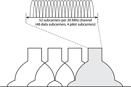
Figure 10-5: 20 MHz HT (802.11n) channel
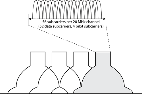
Figure 10-6: 40 MHz HT (802.11n) channel
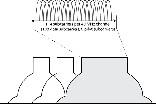
Figure 10-7: Channel bonding


A standard 20 MHz HT channel reserves some frequency bandwidth at the top and bottom of the channel to avoid interference with adjacent 20 MHz HT channels. When two 20 MHz HT channels are bonded together, there is no need to reserve this bandwidth at the bottom of the higher channel and at the top end of the lower channel. Therefore, an HT (802.11n) 40 MHz channel uses this spectral space to add two more subcarriers, giving a total of 114 subcarriers instead of 112.
Modulation and Coding Scheme
The 802.11n amendment defines data rates with a modulation and coding scheme (MCS). Non-HT radios that used OFDM technology (802.11a/g) defined data rates of 6 Mbps to 54 Mbps based on the modulation that was used. HT radios, however, define data rates based on numerous factors including modulation, the number of spatial streams, channel size, and guard interval. Each modulation coding scheme is a combination of these multiple factors. Seventy-seven modulation coding schemes exist for both 20 MHz HT channels and 40 MHz HT channels. There are eight mandatory modulation and coding schemes for 20 MHz HT channels, as shown in Table 10-1. The eight mandatory MCSs for 20 MHz channels are comparable to basic (required) rates.
Table 10-1: Mandatory modulation and coding schemes—20 MHz channel
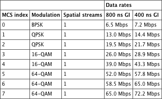
As you can see from Table 10-1, the modulation type, the guard interval, and the number of spatial streams all determine the eventual data rate. The guard interval (GI) and its two alternative lengths will be explained in the “HT Capabilities Element” section of this chapter. Table 10-2 depicts the modulation and coding schemes for a 20 MHz channel using four spatial streams.
Table 10-2: MCS—20 MHz channel, four spatial streams

Table 10-3 depicts the modulation and coding schemes for a 40 MHz channel using one spatial stream.
Table 10-3: MCS—40 MHz channel, one spatial stream
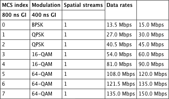
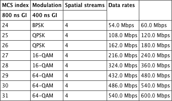
Table 10-4 depicts the modulation and coding schemes for a 40 MHz channel using four spatial streams.
Table 10-4: MCS—40 MHz channel, four spatial streams
Other factors such as the use of unequal modulation can also determine the final data rate. As depicted in Table 10-5, different spatial streams may use different modulation methods.
Table 10-5: MCS—40 MHz channel, four spatial streams, unequal modulation

HT PHY
When an MPDU (802.11 frame) is sent down from layer 2 to the Physical layer, a preamble and PHY header are added to the MPDU. This creates what is called a PLCP Protocol Data Unit (PPDU). The main purpose of the preamble is to use bits to synchronize transmissions at the Physical layer between two 802.11 radios. The main purpose of the PHY header is to use a signal field to indicate how long it will take to transmit or receive the 802.11 frame (MPDU). The 802.11n amendment defines the use of three PPDU structures that use three different preambles. One of the preambles is a legacy format, and two are newly defined HT preamble formats.
Non-HT Legacy
The first PPDU format is called non-HT and is often also referred to as a legacy format because it was originally defined by the 802.11a amendment for OFDM transmissions. As pictured in Figure 10-8, the non-HT PPDU consists of a preamble that uses short and long training symbols, which are used for synchronization. An OFDM symbol consists of 12 bits. The header contains the signal field, which indicates the time needed to transmit the payload of the non-HT PPDU, which of course is the MPDU (802.11 frame).
Figure 10-8: 802.11n PPDU formats
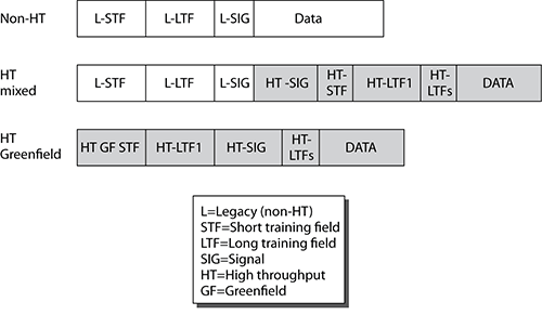
Support for the non-HT legacy format is mandatory for 802.11n radios, and transmissions can occur only in 20 MHz channels. The non-HT format effectively is the same format used by legacy 802.11a and 802.11g radios.
HT Mixed
The first of the two new PPDU formats defined in the 802.11n amendment is the HT mixed format. As shown in Figure 10-8, the beginning of the preamble contains the non-HT short and long training symbols along with the L-SIG field that can be decoded by legacy 802.11a and 802.11g radios. The rest of the HT mixed preamble and header cannot be decoded by legacy 802.11a/g devices. Non-802.11n receivers will not be able to read the frame, but the length field in the legacy section of the header will allow them to know how long the medium is going to be busy for, and they will therefore stay silent without having to do an energy detect at each cycle. The HT mixed format will likely be the most commonly used format because it supports both HT and legacy 802.11a/g OFDM radios. The HT mixed format is also considered mandatory, and transmissions can occur in both 20 MHz and 40 MHz channels. When a 40 MHz channel is used, all broadcast traffic must be sent on a legacy 20 MHz channel so as to maintain interoperability with the 802.11a/g non-HT clients. Also, any transmissions to and from the non-HT clients will have to use a legacy 20 MHz channel.
HT Greenfield
The second of the two new PPDU formats defined by the 802.11n amendment is the HT Greenfield format. As pictured in Figure 10-8, the preamble is not compatible with legacy 802.11a/g radios, and only HT radios can communicate when using the HT Greenfield format. Support for the HT Greenfield format is optional, and the HT radios can transmit by using both 20 MHz and 40 MHz channels.
Analysis of PPDUs
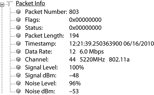
PLCP headers cannot be seen in a protocol analyzer because an 802.11 network interface card (NIC) will strip off the PLCP header and pass only the MPDU up to the MAC layer. NIC cards do, however, pass some packet information up along with every frame. Figure 10-9 shows typical packet information statistics that you can obtain when using a protocol analyzer. Some of these statistics come from information held within the PLCP header.
Figure 10-9: Packet information
HT MAC
So far, we have defined enhancements to the Physical layer that 802.11n radios use to achieve greater bandwidth and throughput. The 802.1n amendment also addresses new enhancements to the MAC sublayer of the Data-Link layer to increase throughput and improve power management. Medium contention overhead is addressed by using two new methods of frame aggregation. Reduced interframe spacing and block acknowledgments are also used to limit the amount of fixed MAC overhead. Finally, two new methods of power management are defined for HT clause 20 radios.
These MAC layer enhancements and their frame exchanges will be discussed in more detail, and we will discuss their relevant fields throughout this chapter.
Wi-Fi Alliance
Before the 802.11n amendment was ratified, HT technology was already being developed, certified, and sold. The Wi-Fi Alliance had developed a vendor certification program called Wi-Fi CERTIFIED 802.11n draft 2.0. This certification program, as the name suggests, certified products against draft 2.0 of the 802.11n amendment. Draft 2.0–certified equipment supports a maximum data rate of 300 Mbps, which is half the maximum data rate specified in the ratified amendment. Since the publication of the 802.11n amendment, the Wi-Fi alliance has replaced this certification program with the more simply named Wi-Fi CERTIFIED n. This new certification program has some mandatory requirements and optional capabilities that can be tested if implemented, as shown in Table 10-6. All certified products must also support both Wi-Fi Multimedia (WMM) QoS mechanisms and WPA2 security mechanisms.
Table 10-6: Wi-Fi CERTIFIED n features
| Feature | Description | Type |
| Two spatial streams* | Can transmit and receive two spatial streams for double the throughput. | Mandatory |
| A-MSDU and A-MPDU in receive mode | Frame aggregation: Increases the maximum frame size, making the data transfer more efficient. | Mandatory |
| Block acknowledgment | Stations can acknowledge several frames at once, reducing the overhead of acknowledging every data frame. | Mandatory |
| Three spatial streams** | Increases throughput by sending data over three spatial streams as opposed to two. | Tested if implemented |
| 2.4 GHz operation*** | 2.4 GHz ISM band operation; must be backward compatible with HR-DSSS and ERP equipment. | Tested if implemented |
| 5 GHz operations*** | 5 GHz UNII band operation, must be backward compatible with OFDM equipment. | Tested if implemented |
| 40 MHz channels in the 5 GHz band | Bonding two channels together to double throughput. 40 MHz operation is supported by the Wi-Fi Alliance in the 5 GHz band. Vendors are free to implement 40 MHz channels in the 2.4 GHz band, but 40 MHz 2.4 GHz operation will not be tested by the Wi-Fi Alliance. | Tested if implemented |
| 20/40 MHz coexistence mechanicals in the 2.4 GHz band** | Access points sense nearby legacy 802.11 wireless equipment operating on the same frequency and enable 20 MHz protection mechanisms. | Tested if implemented |
| Greenfield preamble | The Greenfield preamble improves efficiency of the 802.11n networks in the absence of legacy devices. | Tested if implemented |
| SGI, 20 MHz and 40 MHz channels | The GI is the time that a transmitter waits between sending symbols. Short GI is 400 nanoseconds vs. the traditional GI of 800 nanoseconds. | Tested if implemented |
| STBC** | A data stream is distributed in blocks across multiple transmit streams. These transmission streams are then received by the multiple antennas, and the original data stream is reconstructed in the optimal way. | Tested if implemented |
| HT Duplicate Mode (MCS 32) | The same packet is transmitted simultaneously on both the primary and secondary 20 MHz channel of a 40 MHz bonded pair. | Tested if implemented |
| A-MPDU (Transmit Mode)** | Aggregating several MPDUs together into one packet increases overall throughput. | Tested if implemented |
*Client devices are only required to transmit and receive at least one spatial stream.
** Optional features added in the updated 802.11n program.
***Access points that can operate in both the 2.4 GHz and 5 GHz bands are certified as “concurrent dual-band.”
It should be noted that prior to the Wi-Fi CERTIFIED 802.11n draft 2.0 certification program, many WLAN vendors offered pre-802.11n products in the SOHO marketplace. The majority of these products were not interoperable with other vendors’ products and are not compatible with certified Wi-Fi Alliance products.
A white paper from the Wi-Fi Alliance, called “Wi-Fi CERTIFIED n: Longer-Range, Faster-Throughput, Multimedia-Grade Wi-Fi Networks,” is included on the CD of this book.
The 802.11n amendment adds a new field to the 802.11 MAC header, called the HT Control field. The HT Control field is 4 octets long and follows the QoS Control field in the 802.11 MAC header, as shown in Figure 10-10.
Figure 10-10: 802.11 MAC header

Notice how the maximum length for the Frame Body is now 7955. This might at first seem strange because the maximum 802.11 MSDU size is 2304; however, 802.11n introduces frame aggregation, and the maximum A-MSDU is 3839 or 7035 depending upon the STA capabilities plus any security/encryption overhead.
Any MPDU that contains an HT Control field is referred to as a +HTC MPDU.
This section will detail the format of the HT Control field and discuss its different subfields. However, before going into detail, we will discuss how the order bit present in the MAC header of all 802.11 frames is used by 802.11n STAs to indicate that an HT Control field is also present in the MAC header, and we will discuss how a new frame called the Control Wrapper frame adds an HT Control field to existing control frames.
The Order Bit
The 802.11n amendment uses the existing but relatively unused order bit in the Frame Control field of the MAC header (see Figure 10-11) to indicate the presence of an HT Control field in QoS data and management frames.
The original purpose of this bit, as defined in the original 802.11 standard, was to indicate that data must be sent using a strictly ordered class of service. When set to 1, it tells the receiving station that frames must be processed in order. This is still the correct interpretation of the order bit in non-QoS frames, but it is rarely used, and you are unlikely to see it set to anything but 0. The introduction of QoS into the 802.11 standard through the 802.11e amendment negated the need for an order bit, and it was always set to 0 in QoS frames. However, with the 802.11n amendment, this unused bit now has a purpose again. When set to 1 in QoS data and management frames, it indicates that they contain an HT Control field. The HT Control field is only present in one type of control frame, the Control Wrapper frame, which is described next.
Figure 10-11: Order bit of the Frame Control field

Control Wrapper Frame
The Control Wrapper frame is a new control frame introduced by the 802.11n amendment. Its purpose is to carry other control frames along with an HT Control field. Figure 10-12 shows the format of the Control Wrapper frame. The Subtype value for this control frame is 0111, as highlighted in Figure 10-12.
Figure 10-12: Control Wrapper frame
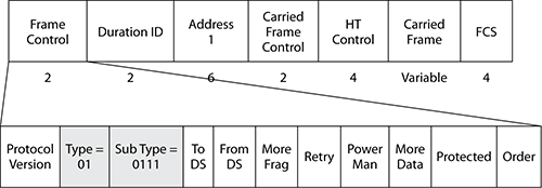
The Duration ID and Address 1 fields are generated using the same rules as would be used for the carried frame. The Carried Frame Control field is set to the same value as the Frame Control field of the carried frame.
Control Wrapper frames are described by using their carried frame name +HTC, for example RTS+HTC or CTS+HTC.
HT Control Field Format
Figure 10-13 shows the format of the HT Control field. This control field is used for link adaptation, TxBF, ASEL, and the RD protocol. Figure 10-14 shows a protocol decode of the HT Control field. A brief description of each field will follow, although when appropriate, a more detailed description of how and when each field is used will be described in context later in this chapter when discussing the relevant 802.11n enhancement.
Figure 10-13: HT Control field format

Link Adaptation Control
The Link Adaptation Control subfield is further subdivided into five more subfields, as shown in Figure 10-15.
Figure 10-14: HT Control field decode

Figure 10-15: Link Adaptation Control subfield format
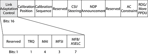
The subfields of the Link Adaptation Control subfield are as follows:
TRQ (Training request) When set to 1, the training request (TRQ) field acts as a request to the receiver of the frame to respond with a sounding PPDU. Sounding PPDUs are used in beamforming to perform over-the-air calibration of a STA’s radios and as a feedback mechanism allowing a STA to estimate the channel in order to calculate a steering matrix. A steering matrix is required for a station to perform transmit beamforming, which will be discussed in greater detail in the “Transmit Beamforming Capabilities” section.
MAI (MCS request (MRQ) or ASEL indicator)
MFSI (MCS feedback sequence identifier) An MCS feedback (MFB) frame is sent in response to an MCS request. The MCS feedback sequence identifier (MFSI) subfield in an MCS feedback (MFB) frame is set to the value of the MCS request field from the frame that contained the request.
MFB/ASELC (MCS Feedback/Antenna Selection Command) When an ASEL indicator is present, the MCS Feedback/Antenna Selection Command (MFB/ASELC) subfield is interpreted as an ASEL command subfield. This subfield will be described in more detail in the “ASEL Capabilities” section of this chapter. Otherwise, it is interpreted at the MFB subfield and contains the feedback response to an MCS request.
Calibration Position
An STA that supports transmit beamforming can perform an over-the-air calibration process in order to correct differences between its transmit and receive chains. This process involves the exchange of four sounding PPDUs. The Calibration Position subfield is set to a value of 0, 1, 2, or 3 in calibration frames to indicate their position within the calibration exchange.
Calibration Sequence
The Calibration Sequence number identifies a calibration sounding exchange. Each of the four packets within the calibration exchange will have the same sequence number.
CSI/Steering
When using sounding frames to transmit feedback about the channel, the Channel State Information (CSI)/Steering subfield identifies the type of feedback being used.
NDP Announcement
A null data packet (NDP) is a PPDU that contains no MPDU. The NDP Announcement subfield indicates that an NDP will follow the current frame. NDPs are used to send sounding PPDUs when no other data needs to be transmitted. If a frame is transmitted that requires an immediate response and also has the TRQ subfield = 1 (request for a sound PPDU), then the receiver can either transmit the MPDU response within a sounding PPDU or send the response MPDU with the NDP Announcement bit set to 1, indicating that an NDP will be transmitted following the current PPDU.
AC Constraint and RDG/More PPDU
The AC Constraint and RDG/More PPDU subfields are used by the Reverse Direction (RD) protocol. A description of this protocol and the use of these subfields follow.
The Reverse Direction Protocol
The RD protocol was introduced in the 802.11n amendment and improves the efficiency of data transfer between STAs. Legacy devices must contend for access to the medium before initiating a data transfer. When using the RD protocol, a STA, having obtained a transmit opportunity (TXOP), may grant other STAs the opportunity to transmit data back within the same TXOP, without requiring the responding STA to contend for the medium before transmission.
The RD protocol defines two STA roles: the RD initiator and RD responder. The RD initiator is the STA that has contended for and obtained the TXOP. The RD initiator will give the RD responder permission to transmit, by sending a reverse direction grant (RDG). The RD initiator will set the RDG/More PPDU subfield to 1, indicating it is an RDG. The Duration ID within an RDP is set to the length of the TXOP remaining.
Upon receipt of an RDG, the RD responder may send one or more PPDUs within a burst. During a response burst, only the RD responder is allowed to transmit. All PPDUs within a burst must be destined to the RD initiator and will be separated by SIFS or RIFS. In all but the last PPDU within a response burst, the RDG/More PPDU subfield is set to 1, which indicates that more PPDUs will follow. The last PPDU in a response burst has the RDG/More subfield set to 0. The transmission of all PPDUs and any expected responses must fit within the remaining TXOP, as indicated by the Duration ID in the RDG. Figure 10-16 shows an example RD protocol exchange.
The RD protocol exchange is summarized as follows:
1. The RD initiator (the TXOP holder) sends a PPDU that requires an immediate response. This PPDU contains an RDG.
2. The RD responder will respond with one or more PPDUs. The first or only PPDU will contain one or more ACKs or BlockAckframes.
3. The last or only PPDU transmitted by the RD responder in the burst will contain any packets that require an immediate ACK or BlockAck response. The last PPDU will also have the RDP/More PPDU subfield set to 0.
This means that when looking at an RDG in a protocol analyzer, you should always see both the RDG/More PPDU and AC Constraint subfields set to 1.
Figure 10-16: Reverse Direction protocol exchange example

If an RD initiator sets the AC Constraint subfield to 1 in an RDG, then the RD responder must only transmit frames that have the same QoS access category (AC) as the last frame it received from the RD initiator. The AC can be determined by looking in the Traffic Identifier (TID) field within the QoS Control field in the MAC header. If the RD initiator obtained its TXOP from the EDCA mechanism, then it must set the RD initiator to 1. If the TXOP has been obtained from any other access mechanism, then it must be set to 0.
HT Action Frames and Information Elements
The 802.11n amendment introduces many new action frames and information elements. These will be summarized in the following sections. When looking at HT protocol decodes, the two most common information elements you are likely to see will be the HT Capabilities Element and HT Operation Element. Later we’ll detail each of these two information elements and their fields and relevant operations.
Action Frames
The 802.11n amendment introduces several new action frames. Figure 10-17 shows the protocol decode for a HT action. The category field in all HT action frames is set to 7 indicating it is an HT action frame. Table 10-7 shows the different HT action frames and how they are categorized by the Action field value.
Figure 10-17: HT action frame decode

Table 10-7: HT action frame, action fields
| HT action field value | Meaning |
| 0 | Notify channel width |
| 1 | SM power save |
| 2 | PSMP |
| 3 | Set PCO phase |
| 4 | CSI |
| 5 | Noncompressed beamforming |
| 6 | Compressed beamforming |
| 7 | ASEL indices feedback |
| 8–255 | Reserved |
Information Elements
If looking at 802.11 a/b/g beacon frames in a protocol analyzer is something you are already familiar with but you have not yet seen an 802.11n beacon decode, then be prepared for a whole wealth of new information displayed in your beacons. The 802.11n amendment greatly expands the 802.11 beacon with the option of up to four new information elements. Table 10-8 shows these new information elements.
Table 10-8: HT beacon information elements

An HTML document containing a full decode of an 802.11n beacon showing both the HT Capabilities Element and HT Operations Element is included on the book's CD.
In draft 2.0 of the 802.11n amendment, the HT Operations Element was called the HT Information Element and is still decoded as such by many wireless analyzers.
HT STAs declare themselves as HT STAs by the transmission of the HT Capabilities Element in Beacon, Probe Request, Probe Response, Association Request, Association Response, Reassociation Request, and Reassociation Response frames. Figure 10-18 shows the format of the HT Capabilities Element. The HT Capabilities Element is 28 octets long and contains 8 fields used by the HT STA to advertise the optional HT capabilities it supports.
Figure 10-18: HT Capabilities Element format

The Element ID for the HT Capabilities element is set to 45, and the length field is set to 26, indicating that another 26 octets follow the length field. The remaining fields of the HT Capabilities element and their subfields will be described in the following sections.
HT Capabilities Info Field
The HT Capabilities Info field is 2 octets long and contains HT capability information bits. Figure 10-19 shows the format of this field. Figure 10-20 shows a decode of the HT Capabilities field.
Figure 10-19: HT Capabilities Info field format

Figure 10-20: HT Capabilities Info field decode

The subfields of the HT Capabilities Information field are described in the following sections.
LDPC Coding Capability
Low-density parity check (LDPC) is a coding method for transmitting data in a noisy environment and provides excellent error correction and performance. An STA indicates it is capable of receiving LDPC-coded packets by setting the LDPC coding bit to 1.
Supported Channel Width Set
The Supported Channel Width Set bit indicates the channel widths supported by a STA.
If an HT station can support only 20 MHz channels, it advertises this by setting the Support Channel Width Set bit to 0. Configuring your 802.11n wireless network to only support 20 MHz channels might be something you do by design in the 2.4 GHz band. This is because deploying 40 MHz HT channels at 2.4 GHz does not scale well in multiple channel architectures. Although we have up to either 13 (Europe) or 11 (North America) channels available in the 2.4 GHz ISM band, there are only three nonoverlapping 20 MHz channels available in North America. When the 20 MHz channels are bonded together to form 40 MHz channels in the 2.4 GHz ISM band, any two 40 MHz channels will overlap, as pictured in Figure 10-21. In other words, only one 40 MHz channel can be used at 2.4 GHz, and the possibility of a channel reuse pattern is essentially impossible.
Channel reuse patterns using 40 MHz channels at 5 GHz are feasible because there are many possible combinations within the UNII bands. The use of 40 MHz HT channels in the 5 GHz UNII bands makes perfect sense because there are up to twenty-four (including channel 165,the 5.8GHz ISM channel available in the U.S.) 20 MHz channels that can be bonded together in various pairs, as pictured in Figure 10-22. When a STA can support both 20 MHz and 40 MHz channels, it sets the Support Channel Width Set bit to 1.
Figure 10-21: Channel bonding—2.4 GHz ISM band

Figure 10-22: Channel bonding—5 GHz UNII bands

SM Power Save
Mobility is one of the main benefits that wireless networks provide. Battery-powered mobile devices no longer need to be tethered to a wired connection and can even transfer data while moving. Unfortunately, RF radios have a big drain on battery resources and can significantly reduce the battery life of the mobile device. It is for this reason that power-save mechanisms have been included in the 802.11 standard from its conception.
HT STAs include multiple radios to support MIMO features such as spatial multiplexing, which transmit multiple streams of data simultaneously. The more radios we use, the more power we require and the faster we drain our batteries. In an attempt to try to combat this problem, a new power-save method that powers down the extra radios when not needed has been included in the 802.11n amendment. This new power save method is called SM Power Save.
Both static and dynamic methods of SM Power Save are defined by the 802.11n amendment. The SM Power Save subfield of the HT Capabilities field of the HT Capabilities Element indicates a STA’s support for the SM Power Save, as indicated in Table 10-9.
Draft 2.0 of the 802.11n amendment interprets an SM Power Save subfield value of 3 as SM Enabled. This might at first seem like a completely different interpretation, but it is not. If SM is enabled, the STA is capable of receiving multiple streams and cannot therefore be in SM Power Save mode. Do not be surprised if you see protocol analyzers reporting an SM Power Save subfield value of 3 as SM Enable instead of SM Power Save disabled until the decodes are updated.
The DFS Gremlin
A large UK manufacturing company recently upgraded its old 802.11g wireless network to an 802.11n 20/40 MHz wireless network in the 5 GHz band, in the hope that 802.11n would provide the throughput and reliability to provide all the company’s mobility needs, including VoIP handsets and real-time control systems. One of the deciding factors when choosing 802.11n was that in the 5 GHz band there were so many nonoverlapping channels, and a 40 MHz multichannel environment was easily obtainable. Shortly after the installation, complaints started to be logged about dropped VoIP calls and intermittent control system lag. After investigation of the wireless network log files, it was noticed that there were Dynamic Frequency Selection (DFS) events causing the access points to change frequencies at the same time as the logged issues. Having consulted the vendor, the company was advised it should disable the DFS channels. However, by doing this, the company was left with only the first four 20 MHz channels in the UNII-1 band, leaving just two 40 MHz HT bonded channels, which is not enough for a multichannel architecture deployment. The company had to reconfigure its access points for 20 MHz HT channels and was not able to experience the full potential of 40 MHz 802.11n operation.
Static SM Power Save
While in static SM Power Save mode, an HT STA maintains only one active receive radio chain. An STA may indicate it is in static SM Power Save in one of two ways: by setting the SM Power Save subfield in the HT Capabilities field of the HT Capabilities Element to 2 in the STA’s Association request frame or by sending an SM Power Save action frame. Figure 10-23 shows the format of a Power Save action frame. An STA will set the SM Power Save Enable bit to 1 and the SM Mode bit to 0 to indicate it is now in static SM Power Save mode. Figure 10-24 shows the decode of an SM Power Save action frame with these settings.
Table 10-9: SM Power Save subfield values
| SM Power Save subfield value | Interpretation |
| 0 | Static SM Power Save mode |
| 1 | Dynamic SM Power mode |
| 2 | Reserved |
| 3 | SM Power Save disabled |
Figure 10-23: SM Power Save action frame format
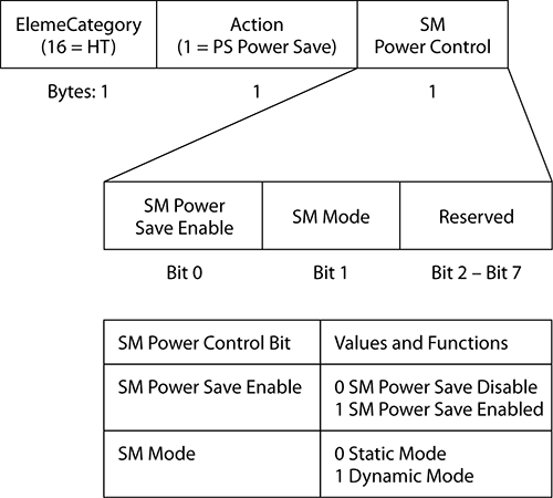
Figure 10-24: Static SM Power Save action frame decode

When a STA operating in static SM Power Save mode wants to receive multiple spatial streams, it must send an SM Power Save action frame to the access point, indicating it is no longer in SM Power Save mode. Figure 10-25 shows the process of enable and disabling static SM Power Save mode using action frames.
Figure 10-25: SM static Power Save

Dynamic SM Power Save
In dynamic SM Power Save, a STA will also turn off all but one receive radio chain; however, the STA may quickly reenable its multiple radio chains upon receipt of a frame addressed to it.
Figure 10-26 shows the dynamic SM Power save process. An access point will typically send an RTS frame using only one spatial stream to wake up a STA’s dozing receive radio chains. An STA will then respond with a CTS frame indicating that multiple spatial streams may now be used for the rest of the current frame sequence. The STA immediately switches back to just having one receive chain enabled when the frame sequence has finished.
Figure 10-26: Dynamic SM Power Save

HT Greenfield
The HT Greenfield PPDU format is one of the two new PPDU formats introduced by the 802.11n amendment, as shown earlier in Figure 10-8. When set to 1, the HT Greenfield bit in the HT Capabilities Element (see Figure 10-19) indicate that a STA is capable of receiving HT Greenfield PPDUs.
Support for the HT Greenfield format is optional. As of this writing, many 802.11n chip manufacturers have not implemented the HT Greenfield format.
Short GI for 20 MHz and Short GI for 40 MHz
For digital signals, data is modulated onto the carrier signal in bits, or collections of bits, called symbols. All the data bits of an OFDM symbol are transmitted across the 48 data subcarriers of a 20 MHz non-HT channel.
802.11a/g radios use an 800-nanosecond guard interval between OFDM symbols. The guard interval is a period of time between symbols that accommodates the late arrival of symbols over long paths. In a multipath environment, symbols travel along different physical paths, and therefore some symbols arrive later or earlier than others. A “new” symbol may arrive at a receiver before a “late” symbol has been completely received. This is known as intersymbol interference (ISI) and usually results in data corruption.
The delay spread is the time differential between multiple paths of the same signal. Normal delay spread is 50–100 nanoseconds, and a maximum delay spread is about 200 nanoseconds. The guard interval should be two to four times the length of the delay spread. Think of the guard interval as a buffer for the delay spread. The normal guard interval is an 800-nanosecond buffer between symbol transmissions. As pictured in Figure 10-27, a guard interval will compensate for the delay spread and help prevent intersymbol interference. If the guard interval is too short, intersymbol interference may still occur.
Figure 10-27: Guard interval
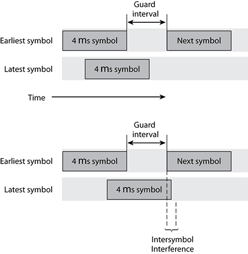
802.11n also uses an 800-nanosecond guard interval; however, a shorter 400-nanosecond guard interval is optional. A shorter guard interval results in a shorter symbol time, which has the effect of increasing data rates by about 10 percent. If the optional, short guard interval of 400 nanoseconds is used with an 802.11n radio, throughput will increase, but the odds of an intersymbol interference occurrence increases. If intersymbol interference does indeed occur because of the shorter GI, the result is data corruption. If data corruption occurs, layer 2 retransmissions will increase, and the throughput will be adversely affected. Retransmissions can be seen in a protocol analyzer by examining the retry flag in the Frame Control field of the 802.11 MAC header. Many protocol analyzers report the number of retransmissions as a statistic and can trigger a notification if this statistic goes beyond a configured threshold. A 400-nanosecond guard interval should be used only in good RF environments. If throughput goes down because of a shorter GI setting, the default guard interval setting of 800 nanoseconds should be used instead.
The short GI for 20 MHz and short GI for 40 MHz bits in the HT Capabilities field of the HT Capabilities Element indicate a STA’s capability to receive packets transmitted with a short GI for 20 MHz and 40 MHz channels, respectively. Table 10-10 shows the encoding for these bits.
Table 10-10: Encoding for short GI for 20 MHz and 40 MHz bits
| Subfield | Encoding |
| Short GI for 20 MHz |
0 = Short GI not supported
1 = Short GI support |
| Short GI for 40 MHz |
0 = Short GI not supported
1 = Short GI support |
TX STBC and RX STBC
Space Time Block Coding (STBC) is a MIMO diversity technique used to improve the reliability of data transfer. STBC adds redundancy into the transmission by transmitting different copies of the data stream from different antennas. The effect multipath has on the received signals means that some of them are received with better quality than the others. Because of redundancy gained from receiving multiple copies of the same data stream, there is a higher chance that the receiving STA will be able to correctly decode the signal.
The TX STBC subfields indicate whether a STA is capable of transmitting PPDUs using STBC, and the RX STBC subfield indicates a STA’s capabilities to receive PPDUs transmitted using STBC. Table 10-11 lists the encoding for these two frames.
Table 10-11: Encoding for RX STBC and TX STBC subfields
| Subfield | Encoding |
| TX STBC |
0 = TX STBC is disabled.
1 = TX STBC is enabled. |
| RX STBC |
0 = RX STBC is disabled.
1 = RX STBC is supported for one spatial stream. 2 = RX STBC is supported for two spatial streams. 3 = RX STBC is supported for three spatial streams. |
HT-Delayed BlockAck
As you already know from Chapter 5, BlockAcks were originally introduced to the 802.11 standard by the 802.11e amendment to improve the efficiency of MAC operations by removing the requirement that a STA must send an immediate acknowledgment (ACK) for every unicast data or management frame. Instead, a STA could send one BlockAck message that effectively includes many ACKs for different frames it has received. The 802.11n amendment makes support for BlockAcks compulsory for all HT STAs.
The 802.11e amendment extended the capabilities of the information field found in many management frames by adding the Immediate BlockAck and Delayed BlockAck bits to indicate a STA’s support for these two BlockAck methods. The 802.11n amendment further extends these two methods and defines HT-Immediate BlockAcks and HT-Delayed BlockAcks.
The HT-Delayed BlockAck subfield of the HT Capabilities Info field indicates a STA’s support for the 802.11n extensions to the Delayed BlockAck method. The HT-Delayed BlockAck subfield is set to 1 when a STA is able to receive an ADDBA request for an HT-delayed BlockAck.
Supporting the HT-Delayed BlockAck is optional, but when implemented, it simplifies the use of delayed BlockAcks. One way it does this is by not requiring an ACK frame to be sent in response to BlockAckReq and BlockAck frames. Figure 10-28 shows the difference between a Delayed BlockAck protocol exchange and an HT-Delayed BlockAck protocol exchange. ACK frames are overhead, and by not requiring these two ACK frames to be transmitted, the medium is freed up for other frame exchanges.
To implement the no ACK policy and indicate that no acknowledgment is expected in response, a STA sets the BAR Ack Policy subfield of the BAR Control field to 1 in a BlockAckRequest and sets the BA ACK Policy subfield of the BA Control field to 1 in a BlockAck. These two subfields are highlighted in Figure 10-29, showing the frame format for both BlockAckRequest and BlockAck frames.
Figure 10-28: Delayed BlockAck protocol exchanges
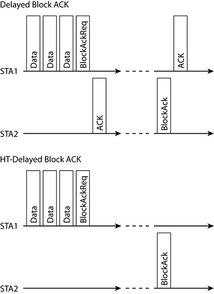
Figure 10-29: BAR and BA ACK subfields

Maximum A-MSDU Length
As pictured in Figure 10-30, every time a unicast 802.11 frame is transmitted, a certain amount of fixed overhead exists as a result of the PHY header, MAC header, MAC trailer, interframe spacing, and acknowledgment frame. Medium contention overhead also exists because of the time required when each frame must contend for the medium.
Figure 10-30: 802.11 unicast frame overhead
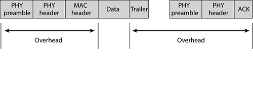
The 802.11n amendment introduces two new methods of frame aggregation to help reduce the overhead. Frame aggregation is a method of combining multiple frames into a single frame transmission. The fixed MAC layer overhead is reduced, and the overhead caused by the random back-off timer during medium contention is also minimized.
The first method of frame aggregation is known as aggregate MAC Service Data Unit (A-MSDU). As you learned in earlier chapters, the MSDU is the layer 3–7 payload of a data frame with a Logical Link Control (LLC) header. As pictured in Figure 10-31, multiple MSDUs can be aggregated into a single frame transmission.
Figure 10-31: A-MSDU

An 802.11n access point using A-MSDU would receive multiple 802.3 frames, remove the 802.3 headers and trailers, and then wrap the multiple MSDU payloads into a single 802.11 frame for transmission. The aggregated MSDUs will have a single destination when wrapped together in a single frame.
The size of an A-MSDU must not exceed the maximum A-MSDU size that a STA is capable of receiving; this is defined in the Maximum A-MSDU Length subfield of the HT Capabilities Info field. An STA can support one of two maximum lengths:
0 = 3839 bytes
1 = 7935 bytes
The entire aggregated frame can be encrypted by using either TKIP or CCMP. It should be noted, however, that the individual MSDUs must all be of the same 802.11e QoS access category. Voice MSDUs cannot be mixed with best-effort or video MSDUs inside the same aggregated frame.
The second type of frame aggregation introduced by the 802.11n amendment is Aggregate MAC Protocol Data Unit (A-MPDU); this method will be discussed shortly when we look at the A-MPDU Parameters field of the HT Capabilities Element.
DSSS/CCK Mode in 40 MHz
Table 10-12 shows the encoding for the DSSS/CCK Mode in the 40 MHz subfield. This subfield indicates an HT 20/40 MHz–capable STA’s ability to support Direct Sequence Spread Spectrum (DSSS) and Complementary Code Keying (CCK), which are the modulation and coding methods use by legacy clause 15 (DSSS 802.11 original) and clause 18 (HR 802.11b) radios. The purpose of this is not to enable DSSS/CCK communication between 20/40 MHz HT STAs but to allow 22 MHz BSS/CCK STAs to transmit within a 20/40 MHz BSS.
Table 10-12: DSSS/CCK mode in the 40 MHz subfield encoding
| Encoding | Values |
| Access points encoding |
0 = BSS does not allow DSSS/CCK in 40 MHz.
1 = BSS does allow DSSS/CCK in 40 MHz. |
| Client STA encoding |
0 = Client STA does not use DSSS/CCK in 40 MHz.
1 = Client STA does use DaSS/CCK in 40 MHz. |
HT 40 MHz–capable client STAs advertise their ability to support DSS/CCK transmissions when associating to an access point (AP) by setting the DSSS/CCK mode in the 40 MHz subfield to 1 in Association and Reassociation response/request frames.
An AP can set the DSSS/CCK mode in 40 MHz subfield to 1 in Beacons and Probe Response frames to indicate that the BSS supports DSSS/CCK transmissions. When an AP sets the DSSS/CCK mode in the 40 MHz subfield to 0, an associated STA cannot send DSSS/CCK transmissions even if the STA has advertised its own ability to do so during association. APs not supporting DSSS/CCK must not include an ERP Information Element in Beacon and Probe response frames and as such not advertise any DSSS/CCK supported rates.
Forty MHz Intolerant
As you have already learned earlier in this chapter, we only have one nonoverlapping 40 MHz channel in the 2.4 GHz ISM band; therefore, using 2.4 GHz 40 MHz channels in multichannel architectures does not scale well. Essentially, 40 MHz channels in the 2.4GHz band are really feasible only when deploying a single-channel architecture (SCA) or a single access point. However, implementing 40 MHz channels in an SCA or on a solitary access point works well only when you are transmitting in a clean RF environment, isolated from other overlapping 2.4 GHz wireless networks.
Even when implementing an HT 2.4 GHz wireless network using only 20 MHz channels, you might still have a problem from neighboring networks that have implemented a 40 MHz BSS. Figure 10-32 illustrates a 40 MHz channel in the center of the 2.4 GHz band—leaving no room for a nonoverlapping 20 MHz channel. It is for scenarios like this that the Forty MHz Intolerant operation of the 802.11n amendment was devised.
Figure 10-32: 40 MHz channel in the 2.4 GHz band

When the Forty MHz Intolerant subfield is set to 1, it prohibits the use of 40 MHz channels. An access point that receives frames with the Forty MHz Intolerant bit set, or reports it, is not allowed to operate a 20/40 MHz BSS.
Advertising Forty MHz Intolerant is allowed only by HT 2.4GHz STAs. HT 5GHz STAs will always set the Forty MHz Intolerant subfield to 0, indicating that 20/40 BSSs are permissible.
L-SIG TXOP Protection Support
The 802.11g amendment introduced protection mechanisms into the 802.11 standard to prevent HR (802.11b) STAs from transmitting at the same time as ERP (802.11g) STAs. Because an HR station does not understand an ERP STA’s OFDM transmissions, the ERP STAs need some method to reserve the medium before transmitting frames that use OFDM. This is done through either RST/CTS or CTS-to-self. In an HT BSS, the HT STAs must also protect their transmission from legacy STAs (802.11 a/b/g). The 802.11n amendment defines many different protection mechanisms, of which L-SIG TXOP protection is one.
The L-SIG TXOP Protection Support subfield in the HT Capabilities Info field is set to 1 to indicate that a STA supports the L-SIG protection mechanism. The L-SIG protection mechanism reserves the medium using the L-SIG (Legacy Signal) field in the HT Mixed PPDU Format header pictured earlier in Figure 10-8. Because this field is in the legacy part of the PPDU header, all STAs should hear it and reserve the medium accordingly. A more detailed description of this and other protection mechanisms will be discussed in the “Protection Mechanisms” section when investigating the HT Operations Element, because many of the fields supporting these protection mechanisms include this information element.
A-MPDU Parameters
You have already learned about one of the two frame aggregation methods, A-MSDU, described earlier in the chapter. The second method of frame aggregation is Aggregate MAC Protocol Data Unit (A-MPDU). As you learned in earlier chapters, the MPDU is an entire 802.11 frame including the MAC header, body, and trailer. As pictured in Figure 10-33, multiple MPDUs can be aggregated into a single frame transmission.
The individual MPDUs within an A-MPDU must all have the same receiver address. Also, the data payload of each MPDU is encrypted separately by using either TKIP or CCMP. Much like MSDU aggregation, individual MPDUs must all be of the same 802.11e QoS access category. Voice MPDUs cannot be mixed with best-effort or video MPDUs inside the same aggregated frame. Please note that MPDU aggregation has more overhead than MSDU aggregation because each MPDU has an individual MAC header and trailer.
The maximum size for an MPDU carried with in an A-MPDU is 4095 bytes. Therefore, when an A-MPDU carries an A-MSDU, it is limited to 4065 bytes plus 30 bytes for the QoS Data overhead (4,095 total). Any A-MSDU longer than 4,065 bytes cannot be included in the A-MPDU.
Figure 10-33: A-MPDU
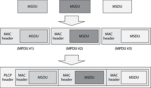
Figure 10-34 shows the format of the A-MPDU Parameters field of the HT Capabilities Element. This field has two subfields: Maximum A-MPDU Length Exponent and the Minimum MPDU Start Spacing.
Figure 10-34: A-MPDU Parameters Field format

Maximum A-MPDU Length Exponent
The first of these two subfields, the Maximum A-MPDU Length Exponent, is used by a STA during association to define the maximum A-MPDU length that the STA can receive. The value for this subfield is an integer between 0 and 3 from which the length in bytes is calculated using the following formula:
2(13 + Maximum A-MPDU Length Exponent) – 1
Most protocol analyzers will do this calculation for you and display the result in the packet decode as pictured in Figure 10-35. The decode shows the A-MPDU Length Exponent subfield set to 3; this is decoded as 64k. The following are the possible values for this field:
0 = 8K
1 = 16K
2 = 36K
3 = 64K
Figure 10-35: A-MPDU Parameters decode

Minimum MPDU Start Spacing
The second subfield in the A-MPDU parameters field is the Minimum MPDU Start Spacing subfield, which specifies the minimum amount of time that must elapse between starting the transmission of one MPDU and starting to transmit the next one. Within an A-MPDU, the number of octets between the start of one MPDU and the start of the next must be counted to make sure that the required amount of time will elapse. If needed, padding bits may be added between MPDUs. The following list shows the encoding for this subfield:
0 = no restriction
1 = 1/4 μs
2 = 1/2 μs
3 = 1 μs
4 = 2 μs
5 = 4 μs
6 = 8 μs
7 = 16 μs
Upon receipt of an A-MPDU, a wireless NIC removes the PPDU header and passes each MPDU up to the MAC layer separately. Therefore, in a protocol analyzer, you will see each MPDU separately. Wireless NIC cards do tell the MAC layer that the MPDU was part of an A-MPDU, and therefore this information can be displayed in a protocol analyzer, as shown in Figures 10-36 and 10-37.
Each A-MPDU must be acknowledged by a BlockAck containing an acknowledgment for each MPDU within the A-MPDU, as shown in Figure 10-37, which shows several frames with the aggregation flag set followed by a BlockAck.
Figure 10-36: A-MPDU packet information flag
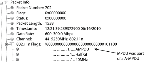
Figure 10-37: A-MPDU packets

Supported MCS Set
A station uses the Supported MCS field to advertise which MCSs it supports. Figure 10-38 shows the structure of the Supported MCS Set field.
Figure 10-38: Supported MCS Set format

The 802.11n amendment defines 77 MCSs that are represented by an MCS index from 0–76. The RX MCS Bitmask subfield has one bit for each of the 77 MCSs. If the first bit of this subfield is set to 1, then the STA supports MCS index 0; if the second bit of the subfields is set to 1, then the STA support MCS index 1; and so on. An example decode of this field in Figure 10-39 shows a STA that supports the first 16 MCSs.
The RX Highest Supported Data Rate subfield defines the highest data rate that the STA supports; however, a STA is not required to provide this information and may set this subfield to 0.
Figure 10-39: Supported MCS decode
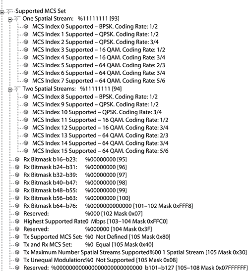
The last four subfields define the TX MCS scheme used. Table 10-13 shows the encoding for these subfields. When the TX MCS Set Defined subfield is set to 1, it indicates that the remaining three subfields will define the TX MCS set. If the TX MCS Set Defined subfield is set to 0, as shown in the decode in Figure 10-36, it indicates the STA is not specifying a TX MCS set and all remaining subfields should also be set to 0. When the TX MCS Set Defined subfield is set to 1 and the TX RX MCS Set Not Equal subfield is set to 0, the STA is indicating it will use the same MCS set defined by the RX MCS Bitmask subfield. When both the TX MCS Set Defined subfield and the TX RX MCS Set Not Equal subfields are set to 1, the remaining two subfields define the TX MCS set in terms of the number of spatial streams and support for unequal modulation (UEQM), as defined in Table 10-13.
Table 10-13: TX modulation set encoding

HT Extended Capabilities Field
Do I hear you say, “HT Extended Capabilities Field? Surely there cannot be any more HT capabilities left to be define?” Unfortunately, there are more, and although at this point it might seem like a never-ending list of fields and features, we encourage you to keep going as you start to make sense of the information shown in the 802.11 protocol decodes, because without this information, the wireless network analyst can get complete lost in all the detail when troubleshooting 802.11n networks.
Figure 10-40 shows the format of the HT Extended Capabilities field. The first subfield indicates a station’s support for phased coexistence operation (PCO), which is a new protection mechanism introduced by the 802.11n amendment. The various protection mechanisms and their operations are going to be discussed in the “Protection Mechanisms” section when looking at the fields of the HT Operations Element. A full discussion of the PCO subfield and the PCO Transmission Time subfield will be left for later in the chapter.
Figure 10-40: HT Extended Capabilities field format

MCS Feedback
The MCS feedback subfield indicates a STA’s ability to provide MCS feedback used during link adaptation. Link adaptation allows an 802.11n wireless network to make use of MIMO channel variations and transmit beamforming to dynamically assign an MCS. This is achieved through the transmission of sounding PPDUs. The link adaptation protocol uses subfields of the HT Control field in the MAC header, which were defined earlier in this chapter. An STA can request another station to send a sounding PPDU containing an MFB by sending an MCS request using the MRQ subfield of the HT Control field in the MAC header. The receiving STA may send either an immediate or delayed response to the requester. An STA may also send unsolicited MFBs. The following list shows the encoding of the MCS Feedback field, including which type of MFB response a STA supports:
0 = MFB not supported
1 = Reserved
2 = Only unsolicited MFB supported
3 = STA can respond to an MRQ and send unsolicited MFBs
A full description of link adaptation operations is beyond the scope of this chapter.
+HTC Support
The +HTC Support subfield indicates a STA’s support for receiving frames that include the HT Control field in the MAC header. STAs advertise their ability to receive +HTC frames by setting the +HTC Support subfield to 1.
When a STA that does not support +HTC frames receives a +HTC frame destined for another STA, it must still read the duration ID and calculate the CRC.
RD Responder
You have already looked at the Reverse Direction (RD) protocol in this chapter when describing the HT Control Field in the MAC header. The RD Responder subfield of the HT Extended Capabilities field indicates a STA’s ability to act as an RD responder. An STA indicates its ability to send data to an RD initiator in response to an RDG by setting the RD Responder subfield to 1.
Transmit Beamforming Capabilities
The 802.11n amendment proposes an optional PHY capability called transmit beamforming (TxBF). Beamforming technology, which has been used in radar systems for many years, is also known as a phased-array antenna system and is often referred to as smart antenna technology.
The two major types of smart antenna array systems include a switched array and an adaptive array. As pictured in Figure 10-41, a switched antenna array uses a number of fixed beam patterns, while an adaptive antenna array maneuvers the beam in the direction of a targeted receiver. 802.11n performs chip-based TxBF and does not require special antennas. By manipulation of the transmitted signal through the use of multiple antennas the signal is optimized at specific locations.
Figure 10-41: Antenna arrays and beamforming
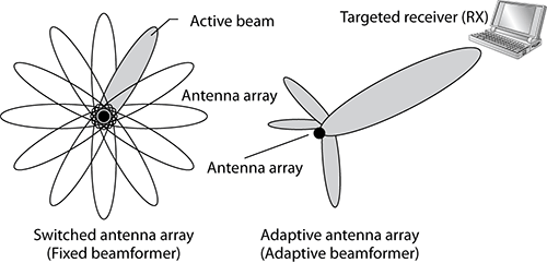
Transmit beamforming is a method that allows a MIMO transmitter using multiple antennas to “focus” the transmissions in a coordinated method much like an adaptive antenna array. The focused transmissions are sent in the best direction of a receiver (RX). When multiple copies of the same signal are sent to a receiver, the signals will usually arrive out of phase with each other. If the transmitter (TX) knows about the receiver’s location, the phase of the multiple signals sent by a MIMO transmitter can be adjusted. When the multiple signals arrive at the receiver, they are in-phase, resulting in constructive multipath instead of the destructive multipath caused by out-of-phase signals. Carefully controlling the phase of the signals transmitted from multiple antennas has the effect of emulating a high-gain unidirectional antenna or “steering” the beams.
Because transmit beamforming results in constructive multipath communication, the result is a higher signal-to-noise ratio and greater received amplitude. Therefore, transmit beamforming will result in greater range for individual clients communicating with an access point. Transmit beamforming will also result in higher throughput because of the higher SNR, which allows for the use of more-complex modulation methods that can encode more data bits. The higher SNR also results in fewer layer 2 retransmissions.
The HT Capabilities Element has a Transmit Beamforming Capabilities field 4 octets in length, which is used to advertise the beamforming capabilities of an HT STA. Figure 10-42 shows the structure of the Transmit Beamforming Capabilities field. As we take a look at the operation of TxBF, some of these subfields will be discussed. Table 10-14 provides a summary and encoding for all the subfields within the Transmit Beamforming Capabilities field.
Figure 10-42: Transmit Beamforming Capabilities field format
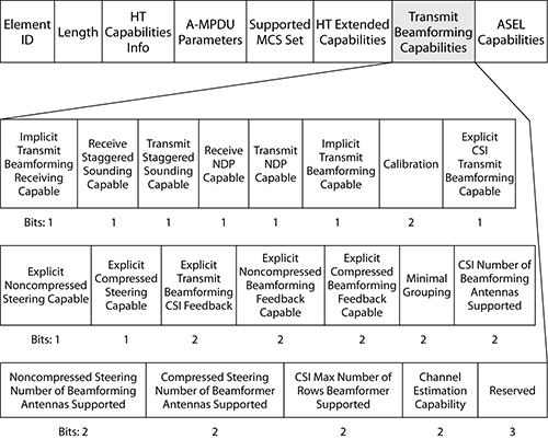
Table 10-14: Transmit Beamforming Capabilities subfields
| Subfield | Description | Encoding |
| Implicit Transmit Beamforming Receiving Capable | Indicates a STA’s capability to receive TxBF frames using implicit feedback |
0 = Not supported
1 = Supported |
| Receive Staggered Sounding Capable | Indicates a STA’s capability to receive staggered sounding frames |
0 = Not supported
1 = Supported |
| Transmit Staggered Sounding Capable | Indicates a STA’s capability to transmit staggered sounding frames |
0 = Not supported
1 = Supported |
| Receive NDP (Null Data Packet) Capable | Indicates a STA’s capability to interpret received NDPs and sounding frames |
0 = Not supported
1 = Supported |
| Transmit NDP Capable | Indicates a STA’s capability to transmit NDPs as sounding frames |
0 = Not supported
1 = Supported |
| Implicit Transmit Beamforming Capable | Indicates a STA’s capability to implement implicit transmit beamforming |
0 = Not supported
1 = Supported |
| Calibration | Indicates a STA’s capability to perform calibration |
0 = Not supported
1 = Can respond to a calibration request 2 = Reserved 3 = Can both initiate and respond to a calibration request |
| Explicit CSI Transmit Beamforming Capable | Indicates a STA’s capability to perform TxBF using CSI (Channel State Information) explicit feedback |
0 = Not supported
1 = Supported |
| Explicit Noncompressed Steering Capable | Indicates a STA’s capability to perform TxBM using explicit noncompressed beamforming feedback |
0 = Not supported
1 = Supported |
| Explicit Compressed Steering Capable | Indicates a STA’s capability to perform TxBF using explicit compressed beamforming feedback |
0 = Not supported
1 = Supported |
| Explicit Transmit Beamforming CSI Feedback | Indicates a STA’s capability to provide CSI explicit feedback |
0 = Not supported
1 = Delayed feedback 2 = Immediate feedback 3 = Both delayed and immediate feedback |
| Explicit Noncompressed Beamforming Feedback Capable | Indicates a STA’s capability to provide noncompressed beamforming explicit feedback |
0 = Not supported
1 = Delayed feedback 2 = Immediate feedback 3 = Both delayed and immediate feedback |
| Explicit Compressed Beamforming Feedback Capable | Indicates a STA’s capability to provide compressed beamforming explicit feedback |
0 = Not supported
1 = Delayed feedback 2 = Immediate feedback 3 = Both delayed and immediate feedback |
| Minimal Grouping | Indicates the minimal grouping a STA supports for explicit feedback reports |
0 = No Grouping
1 = Groups of 1 or 2 2 = Groups of 1 or 4 3 = Groups of 1, 2 or 4 |
| CSI Number of Beamforming Antennas Supported | Indicates the maximum number of beamformer antennas a beamformee can support when CSI feedback is required |
0 = 1 TX antenna
1 = 2 TX antennas 2 = 3 TX antennas 3 = 4 TX antennas |
| Noncompressed Steering Number of Beamforming Antennas Supported | Indicates the maximum number of beamformer antennas a beamformee can support when noncompressed beamforming feedback is required |
0 = 1 TX antenna
1 = 2 TX antennas 2 = 3 TX antennas 3 = 4 TX antennas |
| Compressed Steering Number of Beamformer Antennas Supported | Indicates the maximum number of beamformer antennas a beamformee can support when compressed beamforming feedback is required |
0 = 1 TX antenna
1 = 2 TX antennas 2 = 3 TX antennas 3 = 4 TX antennas |
| CSI Max Number of Rows Beamformer Supported | Indicates the maximum number of CSI explicit feedback rows a beamformer, calibration initiator, or transmit ASEL initiator can support |
0 = 1 CSI row
1 = 2 CSI rows 2 = 3 CSI rows 3 = 4 CSI rows |
| Channel Estimation Capability | Indicates the maximum number of space time streams for which a channel can be estimated when receiving sounding PPDUs |
0 = 1 space-time steam
1 = 2 space-time streams 2 = 3 space-time streams 3 = 4 space-time streams |
Transmit beamforming relies on the transmitter understanding the characteristics of the MIMO channel in order to calculate a steering matrix needed to be able to steer a beam in the direction of the receiver. In order to characterize the channel correctly, the transmitter must receive some feedback from the receiver. 802.11n beamforming transmitters will try to adjust the phase of the signals based on this feedback. The transmitter is considered the beamformer, while the receiver is considered the beamformee. Two feedback methods are provided by the 802.11n amendment:
Implicit Feedback The beamformer estimates the channel characteristics from the High Throughput Long Training Fields (HT_LTF) in PPDUs it receives from the beamformee.
Explicit Feedback The beamformee estimates the channel characteristics from the High Throughput Long Training Fields (HT_LTF) in PPDUs it receives from the beamformer. The beamformee then sends this information to the beamformer to use in calculating its steering matrix.
Implicit Feedback
Implicit feedback can operate in one of two modes, unidirectional or bidirectional. In unidirectional mode, only one STA is capable of steering beams; in bidirectional, both STAs can steer beams and take on both the beamformer and beamformee roles. Two subfields within the Transmit Beamforming Capabilities field in the HT Capabilities element are used to indicate that a STA supports implicit feedback:
Implicit Transmit Beamforming Capable subfield Indicates that the STA is capable of implementing implicit feedback
Implicit Transmit Beamforming Receiving Capable Indicates that the STA can receive TxBF steered frames using implicit feedback
The beamformer must set both subfields to 1, but the beamformee is only required to set the Implicit Transmit Beamforming Receiving Capable subfield to 1.
The feedback needed to estimate the MIMO channel characteristics is transmitted in sounding PPDUs. A PPDU is identified as sounding by setting the Not Sounding field of the HT Signal field (HT-SIG) in the PPDU header to 0. Many HT-LTFs are needed in order to correctly estimate the channel. Standard PPDUs only contain Data HT-LTFs, but in sounding PPDUs, the Data HT-LTFs can be followed by Extension HT-LTFs.
A beamformer can send a request to the beamformee to transmit sounding PPDUs by setting the Training Request (TRQ) subfield to 1 of the Link Adaptation Control subfield of the HT Control field, shown earlier in Figure 10-15. Sounding frames are used to calibrate the beamformer to improve the performance of TxBF.
Any frame can be used as a sounding frame. NDPs can be used as sounding frames if another frame is not used. If an MPDU that has the TRQ subfield set to 1 requires an immediate response, the beamformee may include the response in a sounding PPDU or set the NDP Announcement subfield of the HT Control field in the MAC header of the response to 1 and then send a sounding NDP after waiting a SIFS. Figure 10-43 shows an NDP announcement frame, and Figure 10-44 shows the NDP announcement frame exchange.
Figure 10-43: NDP announcement

Figure 10-44: NDP announcement frame exchange


Because NDPs are PPDUs that do not contain an MPDU, you will not see them in a protocol analyzer. By examining the TRQ and NDP Announcement subfields of the HT Control field in the MAC header, you might be able to conclude that NDPs are in fact being transmitted even though you do not see them.
Figure 10-45 summarizes the PPDU protocol exchange for unidirectional implicit feedback, and Figure 10-46 summarizes the PPDU protocol exchange for bidirectional implicit feedback.
Figure 10-45: Unidirectional implicit feedback PPDU protocol exchange

Figure 10-46: Bidirectional implicit feedback PPDU protocol exchange

Calibration
Differences between transmit and receive chains in a STA degrade the performance of implicit beamforming. Through over-the-air calibration, a set of correction matrices can be calculated that reduces the differences between a STA’s transmit and receive chains. STAs acting as the beamformer are required to be calibrated before they can use the HT-LTFs to correctly estimate the channel. In this chapter, we will just look at the fields and frames used in the calibration procedure and not worry too much about what information is being transferred and what calculations are being made by the STAs.
The ability for a STA to partake in this over-the-air calibration process is indicated in the Calibration subfield of the Transmit Beamforming Capabilities field of the HT Capabilities element. Table 10-15 shows the encoding for this subfield.
Table 10-15: Calibration subfield encoding
| Value | Interpretation |
| 0 | Is not supported. |
| 1 | An STA can respond to a calibration request but not initiate one. |
| 2 | Reserved. |
| 3 | An STA can initiate and respond to a calibration request. |
The calibration procedure consists of two steps:
1. The first step of the calibration process involves the exchange of sounding PPDUs between the calibration initiator and the calibration responder.
2. The second step of the calibration process involves the transmission of a CSI report, which includes the resulting information gained from the PPDU exchange in step 1.
Figure 10-47 shows the calibration protocol exchange and is outlined next. The Calibration Sequence control subfield of the HT Control field is incremented every time a new calibration procedure is started.
Figure 10-47: Calibration protocol exchange
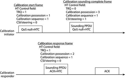
1. The calibration initiator sends a calibration start frame that is a QoS Null+HTC data frame.
The TRQ subfield of the HT Control field is set to 1 to request a sounding PPDU, and the Calibration Position subfield is set to 1 to indicate that this is the first frame in the calibration procedure. Figure 10-48 shows an HT Control field decode for a calibration start frame.
Figure 10-48: Calibration start frame decode
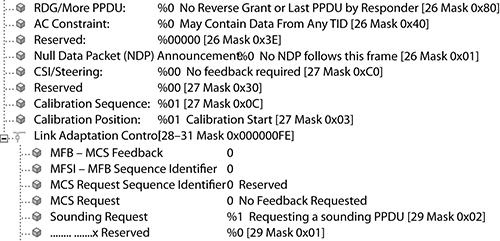
2. After waiting a SIFS, the calibration responder will reply with a sounding PPDU carrying an ACK+HTC control wrapper MPDU.
The Calibration Position subfield is set to 2 to indicate that this is the second frame in the calibration procedure. The Calibration Sequence subfield will be set to the same value as was set in the calibration start frame. Upon receipt of this sounding PPDU, the calibration responder can estimate the MIMO channel. This calibration response frame also contains the TRQ subfield set to 1, requesting the calibration initiator to send a sounding PPDU.
3. The calibration initiator will transmit a Calibration Sounding Complete frame, which is a sounding PPDU containing a QoS Null+HTC data MPDU.
This frame has a Calibration Position value of 3 and upon receipt allows the calibration responder to estimate the MIMO channel. This third frame of the HTC calibration procedure also sets the CSI/Steering subfield of the HT Control field to 1 to request a CSI feedback frame.
4. The calibration responder will send an ACK to acknowledge receipt of the Calibration Sounding Complete frame.
Having successfully exchanged sounding PPDUs, stage 1 of the calibration procedure is now complete.
5. In stage 2 of the calibration procedure, the calibration responder must transmit one or more CSI frames that include a CSI report.
The CSI frame is a new type of action frame introduced by the 802.11n amendment. Figure 10-49 shows the frame format for a CSI action frame. A full description of the CSI action frame is beyond the scope of this chapter.
Figure 10-49: CSI action frame format

Stage 1 of the calibration procedure can be performed by sending the sounding PPDUs in NDPs, in this case any data, management, or control frame can be the calibration start frame (indicated by a calibration position number of 1), which will have the NDP Announcement subfield set to 1. If the calibration initiator does not have any frames to send to the calibration responder, it may set the NDP Announcement subfield using an RTS/CTS exchange.
Explicit Feedback
The advantage of explicit feedback over implicit feedback is that the beamformer does not need to be calibrated; however, explicit feedback does put additional load on the beamformee and increases the transmission overhead. In explicit feedback, the beamformer receives beamforming feedback from the beamformee. This feedback can take one of three forms:
Channel State Information This CSI frame contains MIMO channel coefficients that the beamformer can use to calculate its steering matrix.
Noncompressed beamforming The beamformee calculates the steering matrix and sends it back to the beamformer.
Compressed beamforming The beamformee calculates the steering matrix, compresses it, and sends it back to the beamformer.
An STA shall indicate which feedback methods they support through the use of the Explicit CSI Transmit Beamforming Capable, Explicit Noncompressed Steering Capable, and Explicit Compressed Steering Capable subfields of the Transmit Beamforming Capabilities field in the HT Capabilities Element.
A Beamformee sends beamforming feedback in response to receiving a sounding PPDU from which it can estimate the channel. A beamformee capable of providing explicit feedback must also indicate how soon after receiving a sounding PPDU it will respond with feedback. The options are as follows:
Immediate The feedback response will be sent a SIFS after the sounding PPDU.
Delayed The feedback is sent sometime before the end of the beamformer’s TXOP.
Immediate and Delayed The beamformee is capable of sending immediate or delayed feedback.
The beamformee’s feedback response capabilities are advertised in the Explicit Transmit Beamforming CSI Feedback, Explicit Noncompressed Beamforming Feedback Capable, and Explicit Compressed Beamforming Feedback Capable subfields of the Transmit Beamforming Capabilities field in the HT Capabilities Element. These subfields set a value of 1 to indicate delayed, 2 to indicate immediate, and 3 to indicate support for both.
A detailed description of the information contained within the TxBF feedback message is beyond the scope of this chapter. If you do require more detailed information about the 802.11n amendment, you can always download a copy from the IEEE website at http://standards.ieee.org/getieee802/802.11.html.
Beamforming Summary
Transmit beamforming will work best between 802.11n STAs that have similar capabilities, because the technology depends heavily on feedback from the receiving radio. 802.11 a/b/g radios cannot provide the implicit/explicit feedback used by HT radios that are capable of transmit beamforming. Access points using beamforming can target multiple clients, but only for unicast transmissions. Transmit beamforming is not used for broadcast or multicast transmissions. 802.11n TxBF is not currently tested by the Wi-Fi Alliance. As of this writing, chipset vendors are just starting to release next-generation chipsets that support 802.11n TxBF. However, it will be some time before we start to see products implementing these chipsets and even longer before we see 802.11n TxBF products tested for interoperability. Currently Cisco and Ruckus have their own propriety implementations of beamforming, although it should be said that their beamforming implementations are very different from how TxBF is specified in the 802.11n amendment.
ASEL Capabilities
Antenna selection (ASEL) is a MIMO antenna diversity method used when a STA has more antennas than radio chains. An STA uses ASEL to dynamically create a time-variant mapping of antennas to radio chains, picking the combination of antennas that will yield the best signal-to-noise ratio. This mapping is created based upon CSI. To correctly create this mapping, a STA must carry out an ASEL training frame exchange by sending or receiving a series of sounding PPDUs over all antennas. These sounding PPDUs must all be transmitted within one TXOP.
The training information is transmitted using the ASEL Control subfield of the HT Control field in the MAC header. Figure 10-50 shows the format for this subfield. When the MAI subfield of the Link Adaptation Control subfield of the HT Control field in the MAC header is set to 14, it acts as an ASEL indicator. This indicates that the MFB/ASELC subfield is to be interpreted as an ASEL command (ASELC). The ASELC has two subfields, the ASEL command and ASEL data. Table 10-16 shows the different commands of the ASEL Command subfield. The ASEL Data subfield carries data relating to the command being sent.
Figure 10-50: ASEL Control format
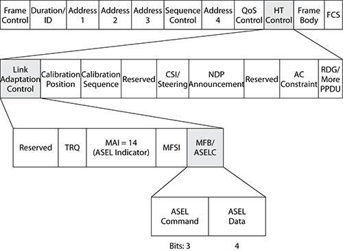
Table 10-16: ASEL commands
| Command | Interpretation |
| 0 | Transmit antenna selection sounding indication (TXASSI) |
| 1 | Transmit antenna selection sounding request (TXASSR) or transmit ASEL sounding resumption |
| 2 | Receive antenna selection sounding indication (RXASSI) |
| 3 | Receive antenna selection sounding request (RXASSR) |
| 4 | Sounding Label |
| 5 | No feedback due to ASEL training failure or stale feedback |
| 6 | Transmit antenna selection sounding indication requesting feedback of explicit CSI (TXASSI-CSI) |
| 7 | Reserved |
An STA advertises its ASEL capabilities through the ASEL Capabilities field of the HT Capabilities Element. Figure 10-51 shows the format of the ASEL Capabilities field. Each of the subfields within the ASEL Capabilities field can be set to 1, indicating that the specified capability is supported or set to 0 when not supported. An ASEL-capable STA will set the Antenna Selection Capable subfield to 1 and then set the other subfields accordingly.
Figure 10-51: ASEL Capabilities format

Transmit ASEL
ASEL supports both transmit and receive diversity methods. Transmit diversity is achieved through the transmit ASEL procedure. Figure 10-52 shows the transmit ASEL procedure. The STA that is responsible for conducting the transmit ASEL procedure is referred to as the ASEL transmitter. The STA that provides the ASEL feedback is defined as the transmit ASEL responder. The following are the steps for transmit ASEL.
1. The transmit ASEL responder may optionally initiate the transmit ASEL procedure by sending an +HTC frame with the ASEL Command subfield set to 1, indicating a transmit antenna selection sounding request (TXASSR).
2. The ASEL transmitter will send sounding PPDUs on each antenna.
These sounding PPDUs may be sounding +HTC frames or sounding NDPs. The +HTC frames have the ASEL command subfield set to 0, indicating transmit antenna selection sounding indication (TXASSI), or set to 6, indicating TXASSI requesting feedback of explicit CSI (TXASSI-CSI). If using sounding NDPs, the ASEL transmitter will first send a TXASSI or TXASSI-CSI frame but with the NDP Announcement flag set, indicating consecutive sounding NDPs will follow.
Figure 10-52: Transmit ASEL procedure

3. The transmit ASEL responder will use the received sounding PPDUs to estimate the MIMO channel.
4. Next in a separate TXOP, the transmit ASEL responder will then send ASEL feedback using one of two action frames:
- If the ASEL transmitter sent a TXASSI-CSI ASEL command, the ASEL feedback will be sent within a CSI action frame (as shown in Figure 10-49).
- If the ASEL transmitter sent a TXASSI ASEL command, the ASEL responder can provide feedback using either a CSI action frame or an ASEL Indices Feedback action frame.
Figure 10-53 shows the format of an ASEL Indices Feedback action frame; a full explanation of this frame is beyond the scope of this chapter.
Figure 10-53: ASEL Indices Feedback action frame format

Receive ASEL
Figure 10-54 shows the receive ASEL procedure, used for received diversity. The STA, which is conducting the receive ASEL, is referred to as the ASEL receiver, and the STA sending the required sounding PPDUs to the ASEL receiver is defined as the ASEL sounding-capable transmitter.
Figure 10-54: Receive ASEL procedure
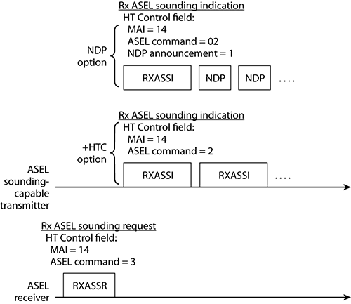
The following steps outline the receive ASEL procedure:
1. The ASEL receiver initiates the receive ASEL procedure by transmitting an +HTC frame with the ASEL command set to 3, indicating a receive antenna selection sounding request (RXASSR).
2. Upon receipt of an RXASSR frame, the ASEL sounding-capable transmitter will begin transmission of the consecutive sounding PPDUs.
The sounding PPDUs can either be +HTC frames or NDPs. The +HTC frames will have the ASEL command set to 2, indicating receive antenna selection sounding indication (RXASSI). When using NDPs, the ASEL sounding-capable transmitter will send an RXASSI frame first with the NDP announcement bit set to 1, indicating sounding NDPs will follow.
3. The ASEL receiver uses different antenna sets to receive the sounding PPDUs and calculates its ASEL mapping.
An STA operation within an HT BSS is controlled by the HT Operation Element. Figure 10-55 shows the format of the HT Operation Element. The HT Operation Element is found in Beacon, Reassociation Response, and Probe Response frames transmitted by an AP.
Figure 10-55: HT Operation Element
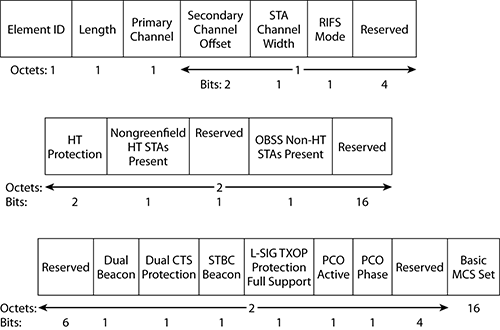
The HT Operation Element ID is 61, and the Length field is set to 22, indicating that another 22 octets will follow the Element ID and Length fields. The reaming fields of the HT Operation Element and their subfields will be described in the following sections.
Primary Channel, Secondary Channel Offset, and STA Channel Width
As you have already seen in this chapter, 802.11n STAs can use either 20 MHz channels or 40 MHz channels. An AP STA uses the Supported Channel Width Set subfield in the HT Capabilities Element to indicate whether it is a 20 MHz BSS or 20/40 MHz BSS. If the Supported Channel Width Set subfield is set to 0, indicating a 20 MHz BSS, then the Primary Channel field of the HT Operation Element indicates the 20 MHz channel number the BSS is operating on.
40 MHz channels consist of two consecutive 20 MHz channels bonded together:
Primary Channel One of the two bonded channels is selected as the primary channel and is used by the access point to communicate with legacy and HT 20 MHz-only STAs, which are associated to the BSS. When the Supported Channel Width Set subfield is equal to 1, indicating a 20/40 MHz BSS, then the Primary Channel field indicates the primary channel number.
Secondary Channel The secondary channel must be one channel directly above or below the primary. The Secondary Channel Offset field in the HT Operation Element indicates whether the primary channel is bonded with the channel above or below.
Table 10-17 shows the encoding for the Secondary Channel Offset field.
Table 10-17: Secondary channel offset encoding
| Value | Interpretation |
| 0 | No secondary channel (20 MHz BSS) |
| 1 | Secondary channel is above the primary channel |
| 2 | Reserved |
| 3 | Secondary channel is below the primary channel |
If the Secondary Channel Offset field is set to 1 or 3, indicating a secondary channel above or below the primary channel, the AP will set the STA Channel Width field in the HT Operation Element to 1, indicating that 40 MHz channels may be used to transmit to an associated STA. If that Secondary Channel Offset field is set to 0, then the STA Channel Width field is also set to 0, indicating that only 20 MHz channels may be used.
RIFS Mode
The 802.11e QoS amendment introduced the capability for a transmitting radio to send a burst of frames during a transmit opportunity (TXOP). During the frame burst, a Short Interframe Space (SIFS) was used between each frame to ensure that no other radios transmitted during the frame burst. The 802.11n amendment defines a new interframe space that is even shorter in time, called a Reduced Interframe Space (RIFS). A SIFS interval is 16 µs for OFDM (10 µs for DSSS), whereas a RIFS interval is only 2 µs. A RIFS interval can be used in place of a SIFS interval, resulting in less overhead during a frame burst. It should be noted that RIFS intervals can be used only when a HT Greenfield network is in place. RIFS can be used only between HT radios, and no legacy devices can belong to the basic service set.
The RIFS Mode field of the HT Operation Element indicates whether the use of RIFS is allowed within the BSS. A value of 1 allows RIFS to be used, and a value of 0 prohibits the use of RIFS.
Protection Mechanisms
The majority of the remaining fields within the HT Operation Element support the operation of various protection mechanisms defined by the 802.11n amendment. These protection mechanisms and their relevant fields will be described next.
In Chapter 5, you have already learned how ERP (802.11g) STAs must use either RTS/CTS or CTS-Self to protect their transmissions from non-ERP (802.11b) STAs. ERP STAs must prevent non-ERP stations who do not understand their OFDM modulation from transmitting at the same time as them. They do this by reserving the medium for the length of their transmission.
The 802.11n amendment requires backward compatibility with 802.11a and 802.1b/g radios. Therefore, the 802.11n amendment defines HT protection modes that enable HT clause 20 radios to be backward compatible with older clause 18 radios (HR-DSSS), clause 17 radios (OFDM), and clause 19 radios (ERP). In additional to RTS/CTS and CTS-to-self, the 802.11n amendment defines some new protection mechanisms, namely, Dual CTS and L-SIG TXOP.
As well as protecting HT transmission against legacy 20 MHz radios, an HT 20/40 MHz–capable STA will have to protect its 40 MHz transmissions against HT STAs that are only 20 MHz capable. The 802.11n amendment defines an optional mode of operation called phased coexistence operation that divides time and alternates between 20 MHz and 40 MHz transmissions.
HT Protection Modes
To ensure backward compatibility with older 802.11 a/b/g radios, an HT access point will operate in one of four protection modes. Much like an ERP access point, the protection modes may change dynamically depending on devices that are nearby or associated to the HT access point. The protection mechanisms used are RTS/CTS, CTS-to-Self, Dual-CTS, or other protection methods. The four modes are as follows:
Mode 0—Greenfield Mode This mode is referred to as Greenfield because only HT radios are in use. All the HT client stations must also have the same operational capabilities. If the HT basic service set is a 20/40 MHz BBS, all the stations must be 20/40 capable. If these conditions are met, there is no need for protection.
Mode 1—HT Nonmember Protection Mode In this mode, all the stations in the BSS must be HT stations. Protection mechanisms kick in when a non-HT client station or non-HT access point is heard that is not a member of the BSS. For example, an HT AP and stations may be transmitting on a 40 MHz HT channel when a non-HT 802.11a access point or client station is detected to be transmitting in a 20 MHz space that interferes with either the primary or secondary channel of the 40 MHz HT channel.
Mode 2—HT 20 MHz Protection Mode In this mode, all the stations in the BSS must be HT stations and are associated to a 20/40 MHz access point. If a 20 MHz–only HT station associates to the 20/40 MHz AP, protection must be used. In other words, the 20/40–capable HT stations must use protection when transmitting on a 40 MHz channel in order to prevent the 20 MHz-only HT stations from transmitting at the same time.
Mode 3—non-HT Mixed Mode This protection mode is used when one or more non-HT stations are associated to the HT access point. The HT basic service set can be either 20 MHz or 20/40 MHz capable. If any clause 18 radios (HR-DSSS), clause 17 radios (OFDM), or clause 19 radios (ERP) associate to the BSS, protection will be used. For the foreseeable future, mode 3 will probably be the most commonly used protection mode because most basic service sets will most likely have legacy devices as members.
HT access points advertise which one of the four HT protection modes an associated HT STA should use through the HT Protection field. Table 10-18 shows the encoding for the HT Operations Element.
Table 10-18: HT Protection field encoding
| Value | Interpretation |
| 0 | Greenfield mode (no protection) |
| 1 | Nonmember protection mode |
| 2 | 20 MHz protection mode |
| 3 | non-HT mixed mode |
Both the Nongreenfield HT STAs Present field and the Overlapping Basic Service Set (OBSS) Non-HT STAs Present field in the HT Operation Element help determine which protection mode an AP should operate in. When the Nongreenfield HT STAs Present field is set to 1, indicating that a nongreenfield-capable STA is associated to the BSS. The OBSS Non-HT STA Present field reports the presence of unassociated non-HT STAs operating on the primary or secondary channel. When the OBSS Non-HT STA Present field is set to 1, the AP will implement either mode 1, nonmember protection, or mode 3, mixed mode protection.
When set to 1, both the Nongreenfield HT STAs Present field and OBSS Non-HT STA Present field can cause neighboring APs to enable HT protection also.
RTS/CTS and CTS-to-Self
When HT protection is enabled within an HT BSS, an HT STA will precede HT transmissions with either an RTS/CTS control frame exchange or a CTS-to-Self control frame using modulation and coding understandable to the STAs that are being protected against. The Duration ID within these control frames causes STAs to update their network allocation vector (NAV), preventing them from initiating a new transmission until the end of the transmitting HT STA’s TXOP.
When protecting the transmission of 40 MHz HT frames against clause 17 (OFDM) radios and clause 19 (ERP) radios, protection mechanism control frames can be sent over the 40 MHz channel using non-HT duplicate transmissions. Non-HT duplicate transmissions allow the two identical 20 MHz non-HT control frames to be transferred simultaneously on both the primary and secondary channels, as pictured in Figure 10-56. Non-HT duplicate transmissions will be sent using clause 17 data rates in the 5 GHz band or clause 19 data rates in the 2.4 GHz band. In Figure 10-56, you can see that non-HT duplicate transmissions are just sending the same data on two adjacent clause 17 or clause 18 20 MHz (52 subcarriers) OFDM channels at the same time. This will cause STAs operating in either the primary or secondary channel to update their NAVs and defer their transmission.
Figure 10-56: Non-HT duplicate format

Dual Beacons, Dual CTS, and STBC Beacons
When implementing STBC, the received signal may be improved by up to 8 dB, resulting in greater range (shown in Figure 10-57). An 8 dB increase in signal strength can yield up to 69 percent more range. This increased range will only apply to STBC frames and therefore does not automatically mean an increased BSS size for all STAs.
Figure 10-57: STBC increased range

Beacon frames are traditionally sent using the lowest basic data rate; because of backward compatibly requirements, this will not be an STBC MCS. Therefore, the only way to truly increase the BSS size and realize the full potential of STBC is to transmit STBC beacon frames (using the lowest STBC MCS). Because HT 802.11n requires backward compatibility with legacy radios and only HT STBC–capable STAs would be able to hear the STBC beacon frames, access points are also required to transmit a standard non-STBC beacon, referred to as the primary beacon.
When the Dual Beacon field of the HT Operation Element is set to 1, the AP will transmit both a primary beacon and an STBC beacon. The STBC beacon contains the same BSS information as the primary beacon but will have the STBC Beacon field in the HT Operation Element set to 1, indicating it is an STBC beacon.
Although STBC operation using dual beacons increases the range of our BSS for STBC STAs, it also introduces a new hidden node problem. STBC STAs operating at the greater range, indicated by the gray area in Figure 10-57, will not be able to hear the shorter range non-STBC transmission within the BSS; conversely, non-STBC STAs will not be able to understand the STBC transmissions. To combat this dual hidden node problem, the 802.11n amendment introduces a new protection mechanism called Dual CTS. Dual CTS sets the NAV in STAs that do not support STBC and STAs that can only associate and communicate use STBC because of their physical distance away from the AP.
An AP implements dual CTS protection by setting the Dual CTS protection field of the HT Operation element to 1; this will cause all non-STBC HT STAs within the BSS to transmit an RTS frame address to the AP at the beginning of every TXOP. In response to this RTS frame, the access point will send two CTS frames. One CTS will be transmitted using an STBC frame, and the other CTS will use a non-STBC frame.
Figure 10-58 shows the Dual CTS procedure where the initiating non-AP STA is STBC capable. Figure 10-59 pictures the Dual CTS procedure where the initiating non-AP STA is not STBC capable.
Figure 10-58: Dual CTS, initiating STA is STBC capable
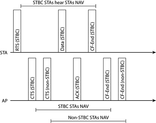
Figure 10-59: Dual CTS, initiating STA is not STBC capable

When the non-AP STA is capable of receiving and transmitting STBC frames, as indicated by the TX STBC and RX STBC subfields in the HT Capabilities Element, it will use an STBC frame to transmit the RTS. If the STA is not STBC capable, the RTS will be a non-STBC frame. The first CTS frame transmitted by the access point will match the frame type of the RTS. This means if the RTS is an STBC frame, as shown in Figure 10-58, then the first CTS transmitted by the access point will also be an STBC frame, and the second CTS will be a non-STBC frame. Conversely, if the RTS is a non-STBC frame, as shown in Figure 10-59, the AP will first transmit a non-STBC CTS followed by a STBC CTS.
If a STA finishes sending data before the end of its TXOP, it may truncate the TXOP by sending a CF-End frame, providing the TXOP has enough time left to send the CF-End frame. CF-End frames were defined in the original 802.11 standard as part of the point coordination function (PCF), a contention-free medium access method. The purpose of CF-End frames is to reset a STA’s NAV to 0, allowing all STAs to contend for access again. When implementing STBC and Dual CTS, there is no guarantee that all STAs within the BSS will see the CF-End frame transmitted by the non-AP STA. Therefore, the AP will respond by sending dual CF-End frames, one using an STBC frame and one using a non-STBC frame, which guarantees all STAs within the BSS will reset their NAV. Figures 10-58 and 10-59 show this Dual CF-End procedure.
When Dual CTS is enabled within a BSS, throughput will be significantly reduced because of the overhead added to every HT TXOP.
The 802.11n amendment uses the CF-End frame original defined as part of PCF. PCF has never been implemented by wireless vendors. However CF-End frames can now be used to truncate TXOPs and are also used in PCO, which will be described later in the protection mechanisms section. So, do not be surprised when you start to see CF-End frames in your 802.11n packet captures.
L-SIG TXOP
L-SIG TXOP protection is an optional Physical layer protection mechanism, which uses the L-SIG (Legacy Signal) field in the HT mixed PPDU header. Figure 10-60 shows the format of this field. As you have already seen in this chapter, a STA advertises its capability to support L-SIG TXOP protection by setting the L-SIG TXOP Protection Support subfield in the HT Capabilities Info field of the HT Capabilities Element. If all HT STAs within a BSS support L-SIG TXOP protection, the AP will set the L-SIG TXOP Protection Full Support field of the HT Operation Element to 1.
When using the Non-HT legacy PPDU format, the Rate subfield of the L-SIG field identifies the date rate that will be used to transmit the MPDU encapsulated in the PPDU, and the Length subfield identifies the length of the MPDU. From these two subfields, the duration needed to transmit the MPDU can be determined. When using HT mixed PPDU format with L-SIG TXOP protection, the Rate and Length subfields can be set to such values that the calculated duration value is equal to the length of time a non-HT station must not transmit for. Because the L-SIG field is in the non-HT legacy part of the PPDU header, it is readable by all non-HT stations.
Figure 10-60: L-SIG field in HT mixed PPDU format

PCO
Another operational mechanism that accounts for the coexistence between 802.11n HT coverage cells and nearby legacy 802.11a/b/g coverage cells is phased coexistence operation (PCO). This is an optional mode of operation that divides time and alternates between 20 MHz and 40 MHz transmissions. The HT access point designates time slices for 20 MHz operations in both primary and secondary 20 MHz channels and designates time slices for 40 MHz transmissions.
An STA advertises its capability to support PCO by setting the PCO subfield in the HT Extended Capabilities field of the HT Capabilities Element. A PCO field value of 1 indicates that the STA is PCO capable and a value of 0 indicates that the STA does not support PCO. An AP STA that supports PCO will make PCO active within the BSS when it determines that a PCO BSS would be more efficient than the current BSS or than a 20 MHz–only BSS. When an AP activates a PCO BSS, it will advertise this by setting the PCO Active field of the HT Operation Element to 1 in its beacons.
It is interesting to note that the 802.11n amendment states that the algorithm an AP uses to decide whether it would be more appropriate to enable a PCO BSS than the current BSS or than a 20 MHz only BSS is “beyond the scope of this standard.” This leaves the decision on how to implement this down to the individual vendors, if their decision is to implement PCO at all.
When a PCO BSS is active, the AP allocates a time slot for a 20 MHz operational phase and a time slot for a 40 MHz operational phase. The AP switches back and forth between the two phases, as is pictured in Figure 10-61. The access point indicates a change in phases through the use of a new action frame called the Set PCO Phase. Figure 10-62 shows the format for the Set PCO Phase action frame. Within this action frame, the PCO Phase Control Field is set to 0 to indicate the start of a 20 MHz phase and a value of 1 indicates the start of a 40 MHz phase. An AP can also advertise a change of state through the PCO Phase field in the HT Operation Element contained in its beacon frames. This field identifies the current operational phase, with a value of 0 indicating a continuation of or change to a 20 MHz phase and with a value of 1 indicating a continuation of or change to a 40 MHz phase.
Figure 10-61: PCO operation
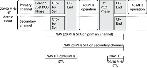
Figure 10-62: Set PCO Phase action frame format

The HT access point uses a non-HT duplicate format CTS-to-Self frame to set the NAV timers of 20 MHz STAs when entering into a 40 MHz phase of operation. It will then send a 40 MHz CF-End frame to reset the NAV in all 40 MHz–capable stations and enter into a period of 40 MHz–only operation. At the end of the 40 MHz period, it will send a Set PCO Phase action frame, indicating the start of a 20 MHz operational phase. This will be followed by a non-HT duplicate format CF-End frame, which will reset the NAV in all 20 MHz STAs, allowing them to contend for access once again. Figure 10-61 shows this procedure.
Both AP and non-AP STAs contain a PCO Transition Time subfield in the HT Extended Capabilities field of the HT Capabilities Element. In an AP, this subfield indicates the transition time between PCO phases of operation. In a non-AP STA, this subfield will be set to the same value as the AP to indicate that it can switch between 20 MHz and 40 MHz phases within the time advertised by the AP. Table 10-19 shows the encoding for this field.
Table 10-19: PCO Transition Time subfield
| Value | Interpretation |
| 0 | Reserved |
| 1 | 400 μs |
| 2 | 1.5 ms |
| 3 | 5 ms |
The main advantage of PCO is that no protection mechanisms are needed during the 40 MHz operational phase. PCO might improve throughput in some situations. However, switching back and forth between channels could increase jitter, and therefore PCO mode is not recommended when VoWiFi phones are deployed.
Basic MCS Set
The last field in the HT Operation Element is the Basic MCS Set. This field has a similar format to the RX MCS Bitmask subfield in the supported MCS Set field of the HT Capabilities Element. Unlike the RX MCS Set subfield, which shows the MCS supported by the AP, the Basic MCS Set field shows only MCS values that are supported by all HT STAs within the BSS. Figure 10-63 shows a decode of this field.
Figure 10-63: Basic MCS set decode

Well done for getting though this chapter. Having investigated all the fields and subfields of the HT Control field, the HT Capabilities Element, and HT Operation Element, along with their associated methods, operations, and frames, you will now have a better understanding of what the 802.11n amendment defines and how it achieves it. You should also be able to start making sense of those massive HT decodes you have seen in your HT packet captures.
This chapter has covered the HT control frame and how its fields support link adaptation and the Reverse Direction (RD) protocol. The chapter has also described how the Control Wrapper frame is used to encapsulate other control frames in order to add an HT Control field to them. The fields and subfields of the HT Capabilities Element and HT Operation Element were also defined.
We investigated the operations of the following 802.11n features and enhancements:
- TxBF
- ASEL
- STBC
- SM Power Save
- Frame aggregation (both A-MSDU and A-MPDU)
- 20/40 MHz BSS and channel bonding
- Short guard interval
- RIFS
- Forty MHz Intolerant
- Delayed block acknowledgements
- MCSs
- HT protection modes
- Dual CTS
- L-SIG TXOP protection
- PCO
As of this writing, chipset vendors are just starting to release the next generation of chipsets using new silicon, which are capable of supporting all the features of the 802.11n amendment. When vendors will implement these chipsets and which features they choose to implement remains to be seen. It is likely that only the features which are tested by the Wi-Fi Alliance will be implemented initially; see Table 10-6 for a list of these features.
Know the three PHY preamble and header formats. Know the differences between non-HT legacy, HT Greenfield, and HT mixed formats and when and why each would be used.
Define the difference between MIMO and SISO. Understand that SISO devices use only one radio chain, whereas the MIMO system uses multiple.
Explain HT channels. Understand the benefit of having additional subcarriers in an HT 20 MHz channel. Be able to explain how channel bonding creates 40 MHz channels and the operation of 20/40 MHz BSS.
Understand the short guard interval. Explain how the guard interval compensates for intersymbol interferences, and describe the use of both 400- and 800-nanosecond GIs.
Explain modulation and coding schemes. Explain how MCS are used to define data rates. Identify the packets and fields where you will find the MCS supported by an HT BSS and by an individual STA. Also be able to identify where you will find a list of the MCS supported by all currently associated STAs.
Understand sounding PPDUs. Know that any 802.11 management, control, or data frame can be carried within a sounding PPDU. Alternatively, when there is no other data to transmit, NDPs can be used to send sounding PPDUs. Understand which HT enhancements use sounding PPDUs and when they are transmitted. Know why and when the NDP announcement subfield is used.
Explain the operation of ASEL. Understand under what conditions ASEL can be used. Describe how ASEL operation uses the subfields of the HT Control field and ASEL Capabilities field. Be able to describe the operation of both transmit and receive ASEL, understanding when an ASEL Indices Feedback action frame is used and when a CSI action frame is used.
Understand TxBF. Be able to describe the operation of both implicit and explicit TxBF, and understand how the subfields within the HT Control Field support them. Be able to explain the calibration process and the reason it is needed.
Explain STBC. Understand how STBC can increase the range of a BSS. Explain how dual beacons and dual CTS are used in a STBC BSS.
Understand SM. Be able to explain how SM increases throughput. Understand the requirement and operation of SM Power Save.
Explain frame aggregation. Be able to demonstrate your understanding of frame aggregation. Understand the differences between A-MSDU and A-MPDU and their respective maximum frame sizes.
Understand the subfields of the HT Control field. Know the definition of each subfield within the HT Control field and how they support the Reverse Direction (RD) protocol.
Define the HT Capabilities and HT Operation Information Elements. Understand the interpretation of the fields and subfields found in both the HT Capabilities and HT Operation elements. Know in which management frames these Information Elements are to be found.
Before you take the exam, be certain you are familiar with the following terms:
Antenna Selection (ASEL)
Aggregate MAC Service Data Unit (A-MSDU)
Aggregate MAC Protocol Data Unit (A-MPDU)
Control Wrapper frame
Dual CTS
Forty MHz Intolerant
Frame aggregation
HT Capabilities Element
HT Control field
HT Operation Element
L-SIG TXOP protection
Modulation and coding scheme (MCS)
Multiple-input multiple-output (MIMO)
Phased coexistence operation (PCO)
Protection modes
Reduced Interframe Space (RIFS)
Reverse Direction (RD) protocol
Short guard interval
Single-input single-output (SISO)
SM Power Save
Space Time Block Coding (STBC)
Spatial Multiplexing (SM)
Transmit Beamforming (TxBF)
1. How many subcarriers are there in an HT 40 MHz channel?
A. 54
B. 56
C. 112
D. 114
2. Which of the PPDU frame formats can be used to protect HT transmissions using L-SIG TXOP?
A. Non-HT legacy
B. HT mixed
C. HT Greenfield
D. HT protection
3. What is the purpose of the order bit in the MAC header in HT QoS data and management frames?
A. Indicates the frame contains a HT Control frame.
B. Indicates the frame contains a HT Capabilities Element.
C. Indicates the frame contains a HT Operations Element.
D. Data must be sent using a strictly ordered class of service.
4. Upon receipt of a reverse direction grant (RDG), the receiving station may do what?
A. Transmit data in the next TXOP to any STA within the BSS
B. Transmit data back to the source of the RDG within the next TXOP
C. Transmit data within the current TXOP to any STA within the BSS
D. Transmit data back to the source of the RDG within the current TXOP
5. 802.11n allows the use of both short and long guard intervals. What are the lengths of the allowable guard intervals?
A. 100 ns and 200 ns
B. 200 ns and 400 ns
C. 300 ns and 600 ns
D. 400 ns and 800 ns
E. 500 ns and 1000 ns
6. What type of stations can advertise that they are 40 MHz intolerant?
A. Only HT 2.4 GHz STAs
B. Only HT 5 GHz STAs
C. Both HT 2.4 GHz and 5 GHz STAs
D. Only non-HT STAs
E. Both HT and non-HT 20 MHz STAs
7. Each A-MPDU must be acknowledged by .
A. an ACK frame
B. a non-ACK frame
C. a BlockAck frame
D. an A-MPDU ACK action frame
8. Which statement correctly describes transmit beamforming feedback methods?
A. Both the beamformer and beamformee estimate the channel in implicit feedback.
B. In implicit feedback, the beamformee estimates the channel, and in explicit feedback the beamformer estimates the channel.
C. In implicit feedback, the beamformer estimates the channel, and in explicit feedback the beamformee estimates the channel.
D. In both implicit and explicit feedback, it is only the beamformee that estimates the channel.
9. When looking at an 802.11n packet decode in a protocol analyzer, you notice the NDP Announcement subfield set. Which of the following statements are true?
A. The NDP Announcement field indicates that the current packet is an NDP.
B. The next packet you will see in your protocol analyzer will be an NDP.
C. This packet is requesting the receiver sends an NDP sounding frame.
D. An NDP will follow the current frame but will not be seen by a protocol analyzer.
10. Over-the-air calibration is used with which of the following HT enhancements?
A. Implicit transmit beamforming
B. Explicit transmit beamforming
C. Antenna selection
D. STBC
E. Spatial multiplexing
11. ASEL is a MIMO antenna diversity method that can be used when .
A. a station has more radio chains than antennas
B. a station has more antennas than radio chains
C. a station has the same number of radio chains as antennas
D. a station has more or less radio chains than antennas but not the same.
12. The MFB/ASELC subfield of the HT Control field is interpreted as ASELC when the MAI subfield of the HT Control field is set to which value?
A. 4
B. 6
C. 8
D. 14
E. 16
F. 18
13. Which of the following statements is true with regard to the relationship between the primary and secondary channels?
A. The secondary channel can be any selectable channel in the same frequency band as the primary channel.
B. The secondary channel must be one channel directly above the primary.
C. The secondary channel must be one channel directly below the primary channel.
D. The secondary channel must be one channel directly above or below the primary channel.
14. In an HT BSS, which has no protection mechanisms enabled, the access point will be in which of the following modes?
A. Mode 0: Greenfield
B. Mode 1: Nonmember
C. Mode 2: 20 MHz protection
D. Mode 3: HT Mixed
15. Space Time Block Coding improves which of the following? (Choose all that apply.)
A. The throughput of a BSS
B. The range of a BSS
C. The STA capacity of a BSS
D. The receive signal strength
16. Dual CTS is a protection mechanism required for use with which HT technology?
A. STBC
B. TxBF
C. SM
D. ASEL
17. Which of the following statements is true regarding PCO?
A. Dual CTS is used to protect HT transmission during the 40 MHz phase.
B. HT STAs are not allowed to transmit outside the 40 MHz phase.
C. No protection mechanisms are needed during the 40 MHz phase.
D. PCO can only be enabled by an access point when in Greenfield mode 0.
18. The Basic MCS Set field in the HT Operation Element found in Beacon, Reassociation Response, and Probe Response frames advertises which of the following?
A. All MCS supported by the access point.
B. MCS supported by all associated STAs.
C. The MCS that all beacon frames will be transmitted at.
D. The BSSs required MCS.
19. Which subfield found within a beacon frame lists the HT MCS supported by the access point?
A. Basic MCS Set
B. RX MCS Bitmask
C. TX MCS Set Defined
D. Support Data Rates
20. What is the purpose of link adaptation?
A. Establishes STA-to-STA communication
B. Allows a Beamformer to estimate the channel in order to calculate a steering matrix
C. Performs over-the-air calibration to reduce the differences between a STA’s transmit and receive radio chains
D. Dynamically assigns an MCS
1. D. When two 20 MHz HT channels are bonded together, there is no need to reserve the bandwidth at the bottom of the higher channel and at the top end of the lower channel. Therefore, an HT (802.11n) 40 MHz channel uses this spectral space to add two more subcarriers, giving a total of 114 subcarriers instead of 112.
2. B. L-SIG TXOP protection is an optional Physical layer protection mechanism, which uses the L-SIG (Legacy Signal) field in the HT mixed PPDU header.
3. A. The original purpose of this bit was to indicate that data must be sent using a strictly ordered class of service. When set to 1, it tells the receiving station that frames must be processed in order. This is still the correct interpretation of the order bit in non-QoS frames; however, it is rarely used, and you are unlikely to see it set to anything but 0. The introduction of QoS into the 802.11 standard through the 802.11e amendment negated the need for an order bit, and it was always set to 0 in QoS frames. However, with the 802.11n amendment, this unused bit now has a purpose again. When set to 1 in QoS data and management frames, it indicates that they contain a HT Control field.
4. D. When using the RD Protocol, a STA, having obtained a transmit opportunity (TXOP), may grant other STAs (through the use of a RDG) the opportunity to transmit data back within the same TXOP, without requiring the responding STA to contend for the medium before transmission.
5. D. 802.11n uses an 800-nanosecond guard interval; however, a shorter 400-nanosecond guard interval is optional. A shorter guard interval results in a shorter symbol time, which has the effect of increasing data rates by about 10 percent.
6. A. An access point that receives frames with the Forty MHz Intolerant bit set, or reports it, is not allowed to operated a 20/40 MHz BSS. Advertising 40 MHz intolerant is only allowed by HT 2.4 GHz STAs. HT 5 GHz STAs will always set the Forty MHz Intolerant subfield to 0, indicating that 20/40 BSSs are permissible.
7. C. Each A-MPDU must be acknowledged by a BlockAck containing an acknowledgment for each in MPDU within the A-MPDU.
8. C. When using implicit feedback, the beamformer estimates the channel characteristics from the High Throughput Long Training fields (HT_LTF) in PPDUs it receives from the beamformee. When using explicit feedback, the beamformee estimates the channel characteristics from the High Throughput Long Training Fields (HT_LTF) in PPDUs it receives from the beamformer. The beamformee then sends this information to the beamformer to use in calculating its steering matrix.
9. D. The NDP Announcement subfield indicates that an NDP will follow the current frame. Because NDPs are PPDUs that do not contain an MPDU, you will not see them in a protocol analyzer.
10. A. Differences between transmit and receive chains in a STA degrade the performance of implicit beamforming. Through over-the-air calibration, a set of correction matrices can be calculated that reduces the differences between a STA’s transmit and receive chains.
11. B. Antenna selection (ASEL) is a MIMO antenna diversity method used when a STA has more antennas than radio chains. An STA uses ASEL to dynamically create a time-variant mapping of antennas to radio chains, picking the combination of antennas that will yield the best signal-to-noise ratio.
12. D. The MAI (MCS request or ASEL indicator) subfield has two interpretations. When set to 14, it is an ASEL indicator, which indicates that we should interpret the MFB/ASELC subfield as an ASEL command (ASELC). Any other value for the MAI subfield is interpreted as an MCS request (MRQ).
13. D. The secondary channel must be one channel directly above or below the primary. The Secondary Channel Offset field in the HT Operation Element indicates whether the primary channel is bonded with the channel above or below.
14. A. In Greenfield mode, only HT radios are in use. All the HT client stations must also have the same operational capabilities. In this mode there is no need for protection.
15. B, D. When implementing Space Time Block Coding (STBC), the received signal may be improved by up to 8 dB resulting in greater range (pictured in Figure 10-57). An 8 dB increase in signal strength can yield up to 69 percent more range.
16. A. Although STBC operation using dual beacons increases the range of our BSS for STBC STAs, it also introduces a new hidden node problem. STBC STAs that are operating at the greater range will not be able to hear the shorter range non-STBC transmission within the BSS. Conversely, non-STBC STAs will not be able to understand the STBC transmissions. To combat this dual hidden node problem, the 802.11n amendment introduces a new protection mechanism called Dual CTS. Dual CTS sets the NAV in STAs that do not support STBC and STAs that can only associate and communicate used STBC because of their physical distance away from the AP.
17. C. The main advantage of PCO is that no protection mechanisms are needed during the 40 MHz operational phase.
18. B. The Basic MCS Set field shows the MCS values that are supported by all STAs within the BSS.
19. B. The 802.11n amendment defines 77 MCSs that are represented by an MCS index from 0–76. The RX MCS Bitmask subfield has one bit for each of the 77 MCSs. A value of 1 indicates support for that particular MCS.
20. D. Link adaptation allows an 802.11n wireless network to use MIMO channel variations and transmit beamforming to dynamically assign an MCS.
