
Chapter 8: Introduction to Policies, Layers, and Rules
In this chapter, we will learn about policy packages, blades used in Access Control policies, and their use in layers. We will look at the possible policy organization methods, rules' structure and capabilities, and their placement based on the packet flows and use of acceleration technology.
In this chapter, we are going to cover the following main topics:
- Access Control policies, layers, and rules
- Packet flows and acceleration
- Best practices for Access Control rules
- Application Control and URL Filtering layer structure
- Logs, tracking depth, and oddities
Access Control policies, layers, and rules
In the previous chapters, we learned how to navigate SmartConsole. Now, let's take a look at Access Control policies, layers, and rules.
Policies
Policies comprise layers containing rules. The basic Access Control policy is, itself, a single layer.
If a policy consists of more than one layer, you may think of the top layer as a collection of coarse filters and subsequent layers as finer filters.
Policies can be organized into policy (or ordered) layers and/or inline layers.
Access Control policies comprise layers with select features. Using Menu | Manage policies and layers… [1], policies [2] can be created [3] or, through the Actions menu [4], cloned [5], and the resultant clones renamed:

Figure 8.1 – Policy and layer management, creating or cloning policies
Cloning is convenient if the redesign of the security policy is required. Using cloned policies allows for a fast fallback by reinstalling the original policy, in case of unforeseen complications.
Note
While policy changes can be rolled back by loading the original policy, any changes made to the objects since the clone was made will persist.
The default Access Control policy, called Standard [1], is created automatically and contains a single layer with a firewall [2] feature enabled:

Figure 8.2 – Default Standard policy
Multiple policies and a common object database
When deciding on the policies that will be used in your organization, for example, a single policy (applicable to all gateways), or a few policies (with separate policies for data centers, headquarters, and branches), or a unique policy for each location, keep in mind that, unless you are working with multi-domain management, you are relying on a common object database. Changes to objects that are published and installed on one of the installation targets (discussed later in this chapter) will remain pending for all others until policies are installed on them. In cases where policies are routinely installed on some of the gateways and only seldomly on others, you may find a backlog of changes made by different administrators in multiple sessions [1] since the last policy installation date [2] on specific gateways, as shown here:

Figure 8.3 – Changes lag in multi-policy implementations
To avoid this situation, either try to schedule periodic policy installations across your infrastructure or install all policies whenever changes are made to any of the objects. Otherwise, you may have to review Audit Logs for these changes before installing a lagging policy.
Layers
Layers can be used in two different modes: policy (ordered) layers and inline layers. Layers can be shared and reused in multiple rules or policies.
Ordered layers
Ordered layers are executed sequentially. Traffic accepted by any rule in the top (or a higher) layer is then matched against the rules of the next layer. Additional ordered layers are created by using the + button in the Access Control section of the policy editor [1] and choosing New Layer… [2] in the layer browser:

Figure 8.4 – Creating a new policy layer
Once Layer Editor is open [1], name the new layer according to its intended application [2] and choose the blades (functions) that it will be responsible for [3]:

Figure 8.5 – Defining the new layer's functions in Layer Editor
In the Policy editor [1], we see the second layer containing the selected features [2]:

Figure 8.6 – Ordered layers view in the Policy editor
When the Policy change depicted in Figure 8.6 is confirmed by clicking the OK button (not shown), the resultant policy structure is visible in the view tree:

Figure 8.7 – Ordered layers view in SECURITY POLICIES
By default, when the first additional ordered layer is added to the policy, the top layer is automatically named Network. I suggest renaming it to reflect the layer's purpose and enabled blades.
Inline layers
Inline layers are executed on traffic matching a rule that contains a layer in its Action column. When creating a new inline layer, it is best to set the new section title in which it'll be contained [1]. Then, in a rule that should contain more specific filters, click the drop-down arrow in the Action column [2], click on Inline Layer [3], and New Layer… [4]:

Figure 8.8 – Creating an inline layer
You'll be greeted with the same Layer Editor as shown in Figure 8.5. Name the layer appropriately and select the blades you need.
The typical use of additional layers, either policy (ordered) or inline, is to add Application Control (APCL)/URL Filtering (URLF), as well as Content Awareness capabilities.
Note that layers with APCL/URLF and Content Awareness have inherent firewall functionality, and there is no need to explicitly select the Firewall option when these layers are created. This allows the use of sources, destinations, and services in rules contained in those layers.
Dedicated layer administration
Layers can have individual permissions assigned to them, allowing for delegation of administration. This is accomplished by navigating to MANAGE & SETTINGS [1], expanding Permissions & Administrators [2], selecting Permissions Profiles [3], and clicking on the create new icon [4]. Then, in a pop-up window, name a new profile to reflect its purpose [5], click Access Control [6], and select Edit layers by the selected profiles in a layer editor [7]:

Figure 8.9 – Creating layer-specific permission profiles
Once this is done, complete the profile configuration by clicking OK.
If policy layers are used, as in the TestPolicy screenshot shown here [1], choose the layer in question [2], right-click it, and click Edit Policy… [3]:

Figure 8.10 – Editing policy layer properties
In a selected policy's pop-up window [1], click on the options menu of the ordered layer [2] and click Edit Layer… [3]:

Figure 8.11 – Invoking the layer editor for the policy layer
For inline layer(s), in the Action column of the unified policy [1], right-click the layers icon [2], click on Inline Layer [3], and then on Edit layer… [4]:

Figure 8.12 – Invoking the layer editor for Inline Layer
In either the ordered layer or inline layer cases, an identical Layer Editor window is opened displaying the selected layer's name [1]. Click on Permissions on the left [2] and, in the bottom portion of the screen under Select additional profiles that will be able to edit this layer, click + [3], and select the profile we created earlier in Figure 8.9 [4]. Click OK in this and the parent window to confirm the change:

Figure 8.13 – Assigning dedicated layer administrators
Administrators with selected profiles will then be able to create or modify rules, have limited object type editing capabilities, and publish the changes for this layer.
Note
Starting with version R81.20, additional permission profiles allowing administrators to submit changes for review, acceptance, and publishing by others are available.
Attention! Layers cannot be installed individually, but only as part of the overall Access Control policy. When a permission profile is assigned to an administrator for a layer allowing policy installation, all published changes by all other administrators outside of that layer will take effect as soon as the policy is installed.
Access Control policy structure preferences
Ordered layers, when used without inline layers, are a less efficient way to organize policies. They are most frequently encountered when the current Check Point environment is upgraded from earlier versions, where APCL/URLF was a function of a separate policy. It makes sense to maintain those if the resultant APCL/URLF layer contains a large number of rules. You are also limited to the use of two ordered layers if the policy targets are gateways running versions R77.30 or earlier. In this case, the first ordered layer can only be Firewall/VPN, and the second, APCL/URLF. The same applies to the SMB gateways running R77.20, the last version of R77, for that category of appliances.
Inline layers are more suitable for new environments, or where a dedicated ordered APCL/URLF layer contains a small number of rules that could easily be migrated to inline layers. An added advantage of inline layers is more granular administration, as individual inline layers containing the same blades may have their own permission assigned to a dedicated administrator or a group.
In large companies, this may allow country-, office-, or department-specific administration of inline layers by local admins while the overarching common security policy section is controlled from headquarters. Another advantage of inline layers is consolidated logging; as parent rules of inline layers do not have tracking options, log entries are created when traffic is processed by the nested rules. In ordered layers, rules in each layer are typically logged, so more logs are generated, impacting log storage and search efficiency.
Ordered and inline layers can be combined into a single policy. One example is the top ordered layer containing common firewall rules for gateways at all locations with inline firewall layers specific to particular sites. The second ordered layer may contain multiple inline layers, each configured with specific sites' APCL/URLF rules.
While you have the capacity to create complex policies, I strongly suggest keeping them as simple as possible.
Shared layers
Layers can be designated as shared. This is accomplished in Layer Editor [1] by checking the Multiple policies and rules can use this layer checkbox [2] under Sharing:

Figure 8.14 – Shared layers
This allows reuse of the same layer in the following:
- Multiple policies: For instance, having a common APCL/URLF and Content Awareness layer applied to different sites in your organization, each governed by an individual policy
- Rules in the same policy: Such as applying common URLF capabilities to different departments
A policy containing shared layers can be installed on a specific target gateway or group without immediately affecting the rest of the gateways in your infrastructure. That said, see this caveat: If the changes are made in a shared layer, but the policies containing it are installed only on select gateways, it is not immediately apparent which gateways are enforcing the latest updated policy. In this case, you can use the Install Policy action to see if any of the changes are lagging for a specific policy. This is shown on the policy installation confirmation screen, and you can safely cancel out of it.
Rules
Let's look at the three types of rules used in the Access Control policies: explicit, implicit, and implied.
Explicit rules
Rules that we can define and see in the policies and layers are called explicit rules.
In addition to explicit rules, there are normally invisible rules called implicit and implied rules.
Implicit rules
Implicit rules are the invisible last rules (also known as Implicit Cleanup Action) in layers. Implicit rules are there to determine how the traffic is treated if it did not match any of the explicit rules in a layer. The behavior of implicit rules for individual layers is defined in Layer Editor [1] for a select layer, under Advanced [2], then the Implicit Cleanup Action [3] properties:

Figure 8.15 – Implicit rules (Implicit Cleanup Action)
Important Note
When constructing your layers, always create an explicit cleanup rule with the action identical to that of Implicit Cleanup Action and configure relevant tracking settings.
Implied rules
Implied rules are created in the Rule Base as a section of Global Properties. They are not editable but can be selectively enabled or disabled in Menu | Global Properties | FireWall. These rules are preconfigured to allow connectivity for a variety of services used by gateways, such as connectivity to AAA servers, and log transfers to management servers, for example:

Figure 8.16 – Implied rules configuration
Or, as actual rules, in the properties of the Access Control policy via Actions | Implied Rules:

Figure 8.17 – Implied rules view
Important Note
Although it looks like these are the individual policy's implied rules settings (accessible via the policy's Actions | Implied Policy | Configuration), these are global parameters and will override the settings found in Global Toolbar | Menu | Global Properties. Not all the implied rules are enabled by default. You may disable those that are not required in your environment.
Rule processing order
The overall order of rule processing looks like this:
- Implied first (applied before explicit rules)
- Explicit rules (all except last)
- Implied before last (applied before the last explicit rule)
- Explicit last (typically, it is any source to any destination, drop, and log)
- Implied last (applied after the last explicit rule, typically empty, as explicit last rules drop all packets)
- Implicit cleanup action (by default, it is any source to any destination, drop, and do not track)
By default, implied and implicit rules are not logged to avoid excessive telemetry. It is possible to enable logging for all implied rules all at once (globally, for all your policies), when it is useful for the duration of troubleshooting sessions, or if you have a specific requirement to log.
Important Note
If you are enabling logging of the implied rules for troubleshooting, set a reminder to disable logging when your troubleshooting session is complete, publish changes, and install policies.
I should also point out that Check Point's own documentation occasionally swaps implied and implicit rule names for no apparent reason. The definitions used here are based on the list of rules displayed by using Show Implied Rules in the policies' Action menu.
The combination of implied, implicit, and explicit rules is referred to as a Rule Base.
Access Control Rule Base components
Let's go over the components of the Access Control Rule Base by looking at the column headers and corresponding content or functionality available in each field:


Table 8.1 – Columns of the Access Control Rule Base
Note that not all these columns are available by default. The Content column becomes visible only after the Content Awareness blade is selected in the layer's properties, and several others could be made visible by right-clicking on the column header and checking the empty boxes.
Now, just because all of these fields and options are available, it does not necessarily mean that all of them should be used in a single layer. Read on to learn about the packet flows and the reasons for using multiple layers.
Packet flows and acceleration
Given today's threat landscape and an ever-increasing emphasis on security, you would think that every packet traversing, entering, or leaving our network must be inspected with prejudice before being allowed to pass. This, clearly, is not the case, as doing that would simply use up unnecessary CPU cycles and negatively impact performance, while not improving security in the least.
Check Point utilizes the following proprietary technologies to achieve the best possible traffic processing speed for its firewalls:
- CoreXL is the load balancing mechanism that assigns CPU cores for either acceleration and packet routing duties, Secure Network Distributor (SND), or for deep packet inspection, FireWall Worker (fwk).
- SecureXL is the traffic routing and acceleration mechanism that increases throughput and connection rate using either software or dedicated acceleration cards (SecureXL instances) and chooses the fwk processes that will handle deep packet inspection for a given connection (Dynamic Dispatcher).
- Multi-Queue is the mechanism that designates multiple CPU cores to process high-volume traffic arriving at the same network interface for acceleration and packet routing.
- HyperFlow is the mechanism allocating multiple cores assigned for deep packet inspection (fwk processes) to individual sessions carrying a massive amount of traffic. This feature is currently in the Early Availability stage and, at the time of writing, it is not known when it'll be released for General Availability.
All these technologies/processes are interacting with each other in real time to dynamically allocate processing resources for traffic flow optimization and to ensure that maximum advantage is taken of the available physical or virtual hardware.
From a security policy organization perspective and rules configuration, we are primarily interested in the SecureXL traffic acceleration mechanism (the term SecureXL is interchangeably applied to a device, driver, acceleration driver, or acceleration layer).
Let's take a look at what it actually does: as connections are being established, state-related information from packets is used to populate and maintain dynamic state tables. For RPC- and UDP-based traffic, virtual sessions are created to track connectionless protocols.
Throughout this process, eligible connections are offloaded to SecureXL connection tables to speed up the processing of subsequent packets and improve throughput. Accept, drop (if enabled), and network address translation (NAT) templates are created to improve session (connection) rates:

Figure 8.18 – SecureXL process outline
Some or all of the subsequent packets of particular established connections may be handled by the SecureXL acceleration driver's optimized inspection operations.
Accept templates improve the rate at which new connections for the existing sessions are established. They contain source and destination IP addresses, destination port numbers, as well as ingress and egress interfaces. Wildcards are used for the source port numbers. New connections for the existing sessions may be established faster if an Accept template is present.
NAT templates allow accelerated connections to avoid taking a long trip through the firewall layer to be subjected to the NAT policy.
Drop templates are disabled by default, as those are based on preconfigured connection rates. If you enable them during a normal firewall operation state, you may run into an unfortunate situation where they will be engaged by the normal spike in your traffic patterns. They are, however, a valuable tool to be used when under denial-of-service (DOS) attacks.
To determine whether part or all of a session or connection can be accelerated, we must look at the packet flow:

Figure 8.19 – Packet flow general description (simplified)
Note that this decision process takes place in both directions; that is, if the preceding diagram is applied to the first packet of a three-way TCP handshake (SYN), then, for a response (SYN-ACK), mentally swap the NIC Port 1 and NIC Port 2 in place to visualize that. For an eligible connection, SYN-ACK is returned via a fully accelerated path.
Note
In the latest versions of the R81.X releases, the number of available paths has increased to nine and may continue growing as Check Point continuously works on ways to handle more traffic in the acceleration layer. For our purposes, it is immaterial.
Let's expand a bit on the inspection chains and content inspection modules shown in Figure 8.19, to see how many hoops the packet may have to jump through if so warranted.
Inspection chains
Inspection chains refer to the sequences of inspection modules the traffic passing through the gateway is subjected to. There are two inspection chains, in chain [1] and out chain [2], allowing for specific actions to be taken on traffic as it enters or exits the gateway. The number of inspection chain modules will vary depending on the release version and the blades activated on the gateway. If you would like to see those, and to see which ones are part of the acceleration layer [3] or firewall layer [4], use the fw ctl chain command in Expert mode:

Figure 8.20 – Inspection chain modules
From this, we can infer that packets can take multiple paths, with accelerated traffic being the shortest, and the traffic relying on firewall instance slow chains and content inspection being the longest.
Content inspection
Content inspection is a complex process, but to glance at what is happening under the hood, let's look at the following figure:

Figure 8.21 – Content inspection, simplified
The previous diagram is a close replica of a segment from the original, created by Moti Sagey and later refined and expanded by Valeri Loukine from Check Point. I highly recommend taking time to read the Security Gateway Packet Flow and Acceleration with Diagrams article by Valeri, as it is exceptionally clear and simple, and can be found here:
Now, seeing what is involved in getting a packet from one interface to another, the reason for the acceleration of eligible packets should become evident. It stands to reason then, that if we can exempt some of the traffic from content inspection, such as that being explicitly trusted, requiring least latency, or where deep packet inspection will not provide additional benefits, our policies should be constructed with it in mind. For ultra-low latency applications where Access Control is still important, such as high-frequency trading or market data delivery, Check Point, in collaboration with NVIDIA, released Quantum Lightspeed appliances capable of 3 microseconds latency.
Best practices for Access Control rules
Now, with what we have learned in the previous section, let's combine Check Point's own best practices for Access Control rules as printed in their user guide, with a few additional suggestions:
- When a new policy is created, a single explicit cleanup rule is automatically included. Change its Track settings to Log.
- On top of the policy, create a rule allowing https and ssh_version_2 access to the gateways and cluster members from the IPs of your Check Point administrators' PCs. This rule, together with the next, the stealth rule, will limit the exposure of your gateways if Gaia's System Management | Host Access | Allowed Hosts contains default settings allowing connectivity from any IP address.
- The second rule from the top should be created, named the stealth rule, and configured to deny direct access to the gateways from Any source.
- Create section titles above these three rules describing their purpose.
- Create additional session titles describing the structure of your policy, so that the rest of the rules will be created under the corresponding sections.
- Create Firewall/Network rules to explicitly accept safe traffic. If inline layers are used, add an explicit cleanup rule to drop everything else for each such layer.
- Create an ordered layer relying on content inspection after the Firewall/Network ordered layer. Alternatively, put rules that examine Access Roles, applications, Data Type, or Mobile Access in an inline layer as part of the Firewall/Network rules. In the parent rule of the inline layer, define the source and destination only.
- Share ordered layers and inline layers when practical.
- If your environment contains gateways with version R77.X, use a two ordered layers structure with Firewall/Network in the first, and APCL/URLF in the second. The policy applied to R77.X cannot contain a Mobile Access blade or Content Awareness.
- In layers relying on content inspection, place rules with objects defined in the Content field closer to the bottom. Rules using File Types objects should be higher than those containing data types.
From the packet flow diagram (Figure 8.19), we know that if content inspection is required, it will always prevent the full acceleration of traffic.
Looking at possible scenarios with or without content inspection:
- Firewall/IPSec VPN blades only are enabled in a layer, with threat prevention disabled (can be fully accelerated).
- Firewall/IPSec VPN blades only are enabled in a layer, with threat prevention enabled. Select sources, destinations, and services are using empty threat prevention profiles (can be fully accelerated).
- Firewall/IPSec VPN and any other blades are enabled in a layer, with threat prevention enabled. Traffic is not exempt from threat prevention (content inspection is engaged).
- Firewall/IPSec VPN and any of the other blades are enabled in a layer, with threat prevention disabled (content inspection is engaged).
Combining this with best practices, we may derive the following:
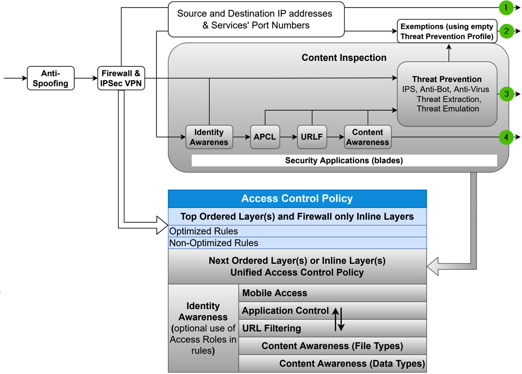
Figure 8.22 – Policy organization based on best practices
To see when rules are considered non-optimized, see sk32578 (https://supportcenter.checkpoint.com/supportcenter/portal?eventSubmit_doGoviewsolutiondetails=&solutionid=sk32578) SecureXL Mechanism | (3) Factors that adversely affect SecureXL performance. As an example, rules with RPC, DCOM, or DCE-RPC services will disable accept templates' creation for all rules located below. These rules, therefore should be placed as close to the end of the Firewall/Network layer as possible.
Threat prevention exemptions
Note
Threat prevention is outside of the scope of this book, but since it is relevant to the structure of the policy and placement of the rules, see this brief subsection for references.
Threat prevention is enabled or disabled on a policy level, not per layer. It consists of the rules allowing the use of sources, destinations, services, and profiles. Custom profiles could be created, and individual security blades enabled or disabled. Create a threat prevention profile, name it Empty [1] and disable all the blades in it.
Use this profile with specific sources [2], destinations [3], and services [4] to exempt specific traffic from content inspection:

Figure 8.23 – The use of an empty threat prevention profile for content inspection exemptions
Figure 8.24 describes a basic Access Control policy structure with firewall/IPSec VPN blades enabled in the top (ordered layer) and a single inline layer with APCL/URLF enabled blades:

Figure 8.24 – Creating an Access Control Rule Base according to best practices
We will go through functional policy creation in Chapter 11, Building Your First Policy, but for now, let's see how the traffic is matched to the rules in your policies.
Column-based matching
In mature organizations with exceptionally granular Access Control policies, it is common to see very long rule bases with hundreds, or even thousands, of rules. As packets making it through the firewall layer require a Rule Base lookup, the length of the Rule Base exerts a toll on performance.
To speed up this process, Check Point uses column-based matching.
Rule-matching in policies works in a columnar plus top-down order. For instance, in a firewall-only enabled policy, the first packet is progressively matched against three fields in this order:
- The Destination column
- The Source column
- The Services & Applications column
The Rule Base is collapsed to a possible matched rules array. Then, top-down matching takes place until the first matching rule is encountered and enforced.
We can use Packet Mode search (described in the previous chapter) to demonstrate the column-based matching.
Note
Packet Mode search works best in either flat (single-layer) policies or policies with inline layers. In cases of ordered layers, Packet Mode search filters only the rules affecting traffic in the currently selected layer.
Figures 8.25 and 8.26 illustrate how traffic matches the rule allowing alerts and notifications from the Check Point Security Management Server (CPSMS) (10.0.0.10) to reach a MailServer (10.30.30.6) using the SMTP protocol (port 25):

Figure 8.25 – Column-based rule matching, part 1
Continuing the process, we see the following:

Figure 8.26 – Column-based rule matching, part 2
If additional blades are enabled in the layer, and the possible matching rules contain access roles, categories, application, and/or content parameters, the first packet is insufficient for policy enforcement decisions.
Note
Policies containing layers with blades other than Firewall/IPSec VPN are referred to as unified Access Control policies. The term should really be unified Access Control layers.
A unified policy classifies the content of subsequent packets until enough is known for traffic identification. As in the previous example, the more that is known about the connection, the more rules are eliminated from the matched rules array.
Examples of classification objects are access roles for source and destination fields, protocols, applications, services, file and content (types), and the direction of transfers:

Figure 8.27 – Classification objects
Consider an attempt to download a .zip file from Google Drive, looking at the Rule Base here:
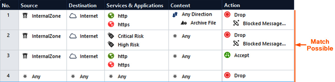
Figure 8.28 – APCL/URLF plus Content Awareness rules column-based matching
The first packet of the connection (SYN) will be matched on all the rules but will be allowed to proceed by rule number 3.
The CoreXL Dynamic Dispatcher forwards SYN to the Context Management Infrastructure (CMI). The unified policy initiates the classification of the packet. Classifier Apps execute on the packet, to create Classifier Objects to match each column in the policy.
After completion of the three-way TCP handshake, the client in the Internal Zone sends an HTTP GET request to download the file.
The HTTP header of the client request contains the host, lh3.googleusercontent.com, which URLF determines not to be a critical or high-risk category (as it is considered a medium-risk category) and is allowed to proceed by rule number 3. Rule number 2 is eliminated from the possible matches array.

Figure 8.29 – APCL/URLF plus Content Awareness rules column-based matching
Protocol streaming and parsing are used to extract the file from the HTTP body in the server's response. The pattern matcher determines the file type is the archive.
The result is returned to the classifier for matching against the remaining rules, and the first match is found to be rule number 1:

Figure 8.30 – APCL/URLF plus Content Awareness rules column-based matching
Kudos to Bob Bent of Check Point for his posts on the subject.
APCL/URLF layer structure
At the time of writing, Check Point's own user guide for versions R81 and up contained this incorrect statement:
"5. Create an Application Control Ordered Layer after the Firewall/Network Ordered Layer. Add rules to explicitly drop unwanted or unsafe traffic. Add an explicit cleanup rule at the bottom of the Ordered Layer to accept everything else.
Alternatively, put Application Control rules in an Inline Layer as part of the Firewall/Network rules. In the parent rule of the Inline Layer, define the Source and Destination"
The screenshot from the official documentation is as follows:
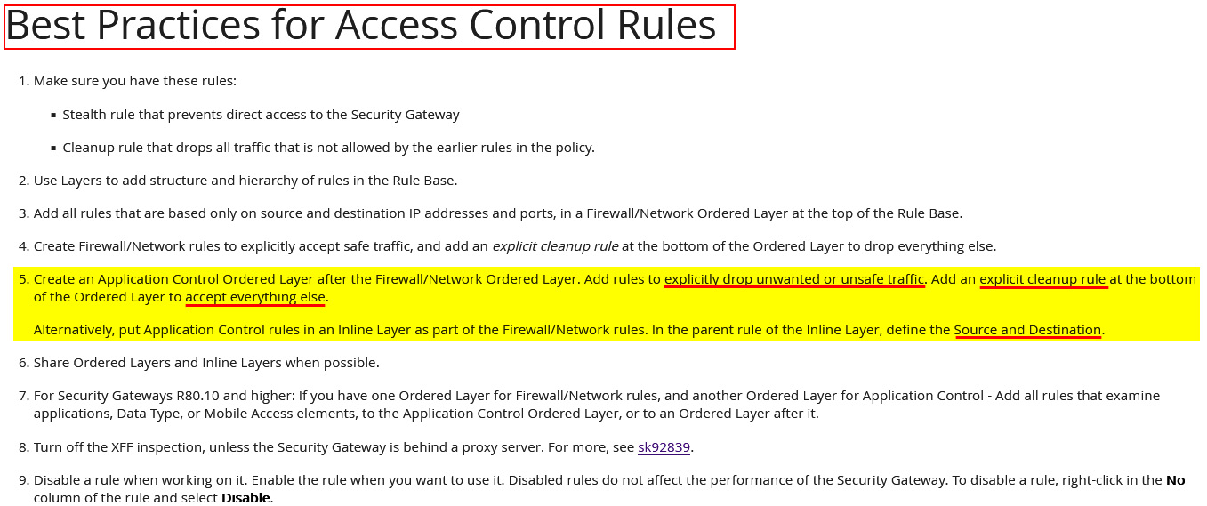
Figure 8.31 – Check Point's Best Practices for Access Control Rules error
If you were to follow this recommendation, then traffic to any IP and port on the internet would be allowed, unless explicit rules are present in the APCL/URLF layer to drop it.
Instead, I suggest using the following approach:

Figure 8.32 – Correct structure for the APCL layer
Let's go over the preceding figure:
- At the top, the section title describes the inline layer.
- Rule 12 (the parent rule of the inline APCL_URLF_Layer). While this example is using InternalZone as a source, you may use a network or a group of networks instead. The use of ExternalZone for the destination is, in my opinion, the best way to define internet in the Firewall/Network policy layer, as the actual Internet object is only available in layers with the Application Control & URL Filtering blade enabled.
The use of Any in the Services & Applications field of rule 12 is explained by the following: many applications, especially those that incorporate voice or video streaming, such as Cisco Webex Teams [1] in the following example, using UDP and additional TCP ports other than 80 and 443 [2]:

Figure 8.33 – Applications using UDP and TCP ports other than 80 and 443
The APCL/URLF blade's properties as shown in the following screenshot [1] state that we are matching web applications on HTTP/HTTPS [2], but this is not the same as allowing all relevant traffic for those applications:

Figure 8.34 – Web application match-on services
Imagine that we have rule-tracking set for the Application Session and Connections. We should see all the relevant connections for the session, HTTP(S), as well as other protocols. In the rules depicted in Figure 8.32:
- Rules 12.1 and 12.2 (blocked category) are there to prevent all web access to the Critical Risk and Uncategorized categories of sites.
- Rule 12.3 (allowed category) allows access to News/Media categories of sites to All_Users. This restricts access based on a combination of networks and users' AD group membership. The use of access roles is possible when the Identity Awareness blade is also enabled in the layer. We'll talk about identity awareness in a later chapter. You may use IP ranges, network objects, or groups instead.
- Rule 12.4 (allowed application) allows access for MS Teams to All_Users.
- Rule 12.5 in tandem with rule 12.6 creates an exemption for access to the Social Networking categories for Human Resources from all the rest All_Users prohibition.
- Rule 12.7 allows access to the rest of the URLs (or web applications) not explicitly denied by previous rules. This is achieved by limiting access to the relevant protocols only.
- Rule 12.8 Is the APCL/URLF layer cleanup rule, dropping the rest of the attempts and logging them.
To generalize this example of the inline layer for APCL/URLF, we can simplify it as follows:
- 12.1 and 12.2 Blocked Categories, including uncategorized; (Block)
- 12.3 Allowed Categories; (Accept)
- 12.4 Allowed Applications; (Accept)
- 12.5 Blocked Categories exemptions; (Accept)
- 12.6 Blocked Categories; (Block)
- 12.7 Allowed Web Browsing to the rest; (Accept)
- 12.8 Block all other traffic; (Drop)
If even finer control is needed, you can use additional (nested) inline layers.
Actions and user interactions (UserCheck)
APCL/URLF rules allow Check Point administrators to craft interactive rules. By combining Drop with Blocked Message [1], you inform users that an attempt to access a site, category, or web application is violating the company security policy [2]. Instead of seeing the This Site can't be reached (ERR_CONNECTION_RESET) message that a simple Drop would result in and logging it as such [3], the action is logged as Block [4]:

Figure 8.35 – UserCheck in APCL/URLF rules
Users are presented with an informative message that does the following:
- Displays a reason for denial of access
- Allows submission of a reclassification request (typically takes 24 hours)
- Provides a Reference number for the incident handling
The preceding informative messages can be seen in the following screenshot:

Figure 8.36 – UserCheck Page Blocked according to security policy
A reference number [1] can be used in tickets submitted to Check Point administrators for review or corrective actions, to easily retrieve relevant logs [2]:
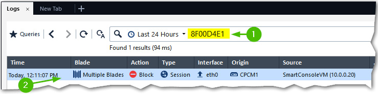
Figure 8.37 – Log retrieval by incident ID reference number
Additional interactions are possible, such as informing users before they are successfully granted access, checkbox consent to abide by the company policy, and redirecting to an external portal (authenticated via a generated pre-shared secret). For the Ask/Inform [1] actions, you can define UserCheck frequency, confirmation conditions (Per rule/category/application/site/data type), and transfer speed limit [2].
Enable Identity Captive Portal [3] is only relevant when the following applies:
- Identity awareness is enabled on the gateway with Browser-based Authentication.
- Identity awareness is used in the layer.
The following screenshot illustrates various Action Settings available to us:

Figure 8.38 – Action Settings
For the Accept action, only Limit can be selected.
Note
Besides the four pre-defined Limit values, additional values and transfer directions can be created using Objects | New | More | Limits. Limits can be bi- or uni-directional. Limits are applied per rule, not per individual connection.
Administrators can modify existing, or create new, UserCheck actions. I strongly suggest keeping all original items in place, creating clones for each, and using those for customization and in rules.
Content Awareness
Content Awareness is not a data loss prevention (DLP) solution. It will certainly improve your overall security posture if you do not have a dedicated solution, but it is not intended to replace one.
In a nutshell, Content Awareness lets you prevent the upload, download, or transfer in any direction of either all or certain types of files, and files containing certain types of data. It works over a limited number of services. It is enabled by default to work with HTTP, HTTPS, HTTP(S) Proxy, SMTP, and FTP.
Additional options are CheckPointExchangeAgent and Squid_NTLM (I am uncertain as to the reason for this last one).
You can create custom data types, but the file types are limited to those provided by Check Point. At the time of writing, there are 62 different file and data types that can be used in the Content Awareness rules.
To use this feature in your rules, the Content Awareness blade should be enabled on the gateway(s) in your policy's Installation Targets and selected in the properties of the layer.
When creating rules for Content Awareness, I recommend explicitly specifying services on which they are enforced, as shown in Rule 14.3 [1] in the following screenshot. Rule 14.4 [2] does not have services specified and you are permitted to install it, but, looking at that rule, we may infer that Content Awareness is enforced on any service:
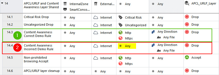
Figure 8.39 – Correct and incorrect rule formats for Content Awareness
This assumption would be incorrect, due to the limitations of the Content Awareness blade.
There is a reason I've chosen to write about Content Awareness after the Actions and User Interactions section.
Note
Do not use UserCheck in the Action field of the Content Awareness rules.
For instance, if the rule is configured to Drop with Blocked Message [1] and you attempt to transfer a file, there will not be a browser-based notification, and in the rule logs you will see the Redirect as Action:

Figure 8.40 – Content Awareness rule with UserCheck, Redirect Action
The good news is that file transfer was prevented:

Figure 8.41 – File transfer prevented with the Content Awareness blade, no UserCheck
The not-so-good news is that you do not have a log entry to prove it to your auditors. Redirect is actually an indicator that Check Point cannot display the message in the browser window and is forwarding it to UserCheck Client. UserCheck Client is available for download from SmartConsole, but I do not recommend using it. This is an old Windows-specific installer. To keep the behavior of your rules and corresponding logs consistent, simply use the Drop or Accept actions for Content Awareness.
You may encounter Redirect in logs for application-specific rules, but it will not be perceived as a data loss event.
Now that we've seen how the rules are constructed and the available actions, let's take a look at how they are tracked and examine a few common cases that may be difficult to interpret without additional explanation.
Logs, tracking depth, and oddities
Tracking for Access Control rules should be configured on a per-rule basis. Either right-click in the Track field of the rule or hover over it with your mouse and click on the drop-down arrow in its top-right corner [1]. The small drop-down box gives you the ability to set some of the options using a one-click operation.
Clicking on More [2] opens a more extensive Track Settings dialog box where, in addition to the same options as above, you can choose the logging level (for rules in layers with APCL/URLF enabled) [3], set Alert [4], choose the Accounting option [5], and select whether Log Generation is set per Connection [6] or per Session [7]:

Figure 8.42 – Track Settings configuration
Note that the Detailed Log and Extended Log options are available only in rules located in layers with either APCL/URLF, Content Awareness, or Mobile Access blades enabled.
When either Detailed Log or Extended Log are selected [8], Track Settings acquires an additional option, Enable Firewall sessions [9]:

Figure 8.43 – Track settings for rules in APCL/URLF layers
This is what each of the Track Settings options is for:
- None: No logging is taking place. Used for noise filtering rules.
- Log: The basic logging level is enabled by default in all new Firewall/Network layer rules. This is the only option available in Firewall/Network only layer rules besides None. If used in the APCL/URLF layers with an application specified in the rule, that application will be logged. If used in a layer with Content Awareness and file/data type specified, that file/datatype will be logged.
- The Detailed Log and Extended Log options become available if either one of these blades is enabled in the layer: Application Control & URL Filtering, Content Awareness, or Mobile Access.
- Detailed Logging: Expands basic Log in APCL/URLF layers to include identified sites and/or applications, even if they are not specified in the rule. As a best practice, use it for cleanup rules.
- Extended Logging: Expands Detailed Logging with raw URLs and filenames in APCL/URLF layers.
- Accounting: Available for all logging options. Provides statistics relevant to connection durations, the amount of transferred data, and the egress interface. Incremented every 10 minutes for existing connections. Necessary for relevant reports in SmartEvent.
- Per Connection: Used to log individual connections in sessions. The default option for all firewall rules.
- Per Session: The default option for all APLC/URLF rules. All sites/applications that are identified by that blade are logged at the start of a session. This log is not updated for the next 3 hours (default setting) or until the session is terminated.
- Per Firewall Session: Becomes available in APCL/URLF layers when either the Detailed Log or Extended Log options are set in the Track field. Enable for all non-application specific APCL/URLF rules with the Accept action (that is, when simple service(s) are specified in Services & Applications).
- Alerts: Can only be enabled when at least one tracking option is chosen. By itself, simply generates Log with the type Alert:

Figure 8.44 – Log type alert
This is useful when trying to draw attention to specific traffic in logs (filtered by Type) in Logs.
The other options for alerts are self-explanatory and could be configured in Menu | Global Properties | Log and Alert | Alerts.
Based on my experience (and the recommendations by Timothy Hall who presented on this subject at the 2022 Check Point Experience conference, and was kind enough to discuss this subject with me), these are the preferred settings for logging:
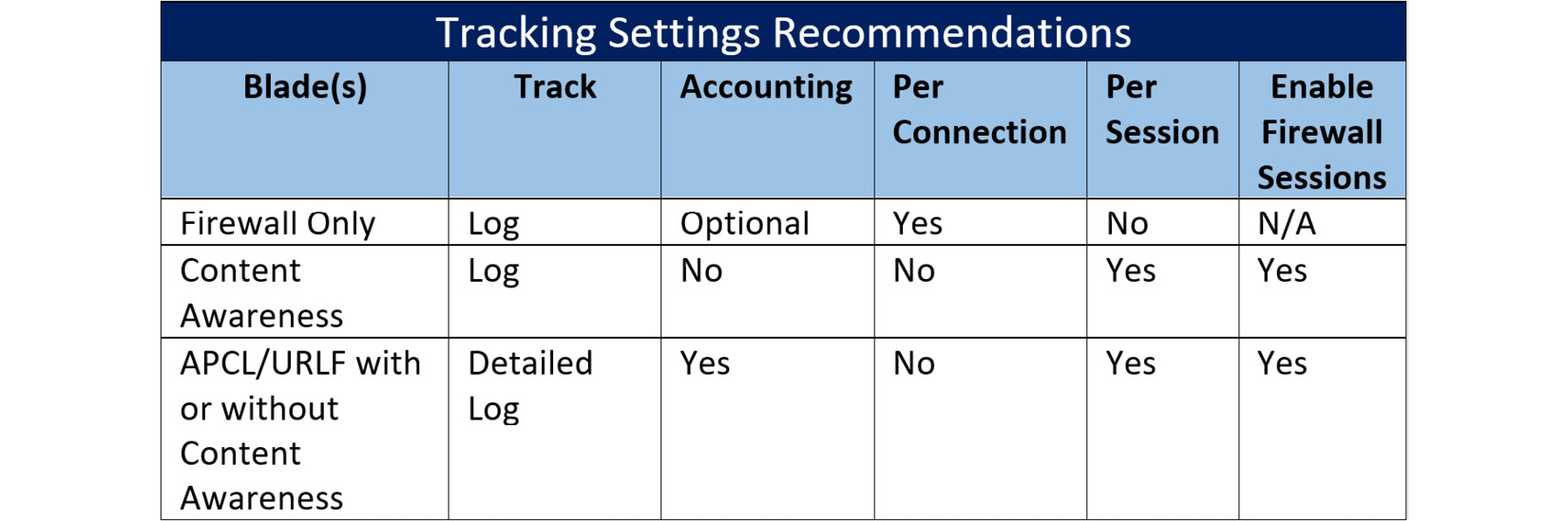
Figure 8.45 – Recommended log generation settings
Note
These are my personal recommendations, and your situation may require different settings.
If, for instance, you need to see NAT data in your APCL/URLF rules for troubleshooting, you may add a rule above the one you are working on – specify a narrow combination of source, destination, and services, and in its Track field, select Detailed Log with Sessions and Connections.
Oddities – CPEarlyDrop and insufficient data passed
There are a few cases that tend to cause headaches for administrators that I'd like to cover at this point. Both of those are shown in the general logs in the following screenshot, filtered by destination IP. Since logs are presented in reverse chronological order, the first one is on the bottom [1] and the second one is on top [2].

Figure 8.46 – Logging edge cases
Let's examine these cases to see how they are manifested, and their causes.
CPEarlyDrop
When we attempt to initiate an SSH connection from sources allowed by the rules in the Application Control layer [1], we expect it to fail on the APCL/URLF layer cleanup rule 13.5 [2]. There is nothing in the rule's logs to indicate that has occurred [3].

Figure 8.47 – CPEarlyDrop – no logs in the presumed matching rule
Instead, we must go to the general logs by way of LOGS & MONITOR | New Tab | Log View and hunt it down, (as shown in the first scenario depicted in Figure 8.46).
When we open the log card for the event, we see the following note [1]: Early Drop: blocking the connection before final rule match. To learn more see sk111643 http://supportcontent.checkpoint.com/solutions?id=sk111643, and Access Rule Name is CPEarlyDrop in APCL_URLF_Layer [2]. Clearly, there is no such rule between rules 13.1 and 13.5, so what is going on?
This is Check Point's policy execution optimization mechanism at work. It is allowed to drop the attempted connection as soon as it determines that there is nothing in your policy that will allow it to succeed. This is great for security and performance but is mildly irritating for administrators.

Figure 8.48 – CPEarlyDrop log card
Insufficient data passed
Let's take a look at the second case. In the following policy, we have a rule allowing an SSH connection to a specific host with a public IP [1]. When we attempt to connect to it, the connection fails and there is nothing in the logs for the corresponding rule [2]:

Figure 8.49 – Insufficient Data Passed, no logs in the expected location
On the odd chance that we've missed something, we can check both cleanup rules, one for the APCL/URLF layer and a general one below it (rules 13.6 and 14), but there is nothing there either. Did we just lose the packet? Not really. This situation is possible if the destination is not responding. In my case, it is a random public IP that is not listening on port 22 [1]. We are presented with the reason: Connection terminated before the Security Gateway was able to make a decision: Insufficient data passed. To learn more see sk113479 [2]. Remember, that this is the Application Control layer. For TCP connections, a service is identified only after the server's response is received. The first packet is allowed to pass and is attributed to the parent rule, which is rule 13 [3] in our case. The connection is, in fact, only an attempted connection at this point.

Figure 8.50 – Insufficient data passed, log for connection to a non-responding host
If you know without a shadow of a doubt that there is a host listening for a connection on the correct service port, there are a few possible explanations:
- You are experiencing asymmetric routing. In this case, the server's responses are being sent via a different route and are not returning to the gateway's interface from which this connection has originated.
- You are prohibited from connecting to that host on that port, by either an external or host-based firewall on the receiving end.
We've seen that the logs in Check Point contain a wealth of information. We have also learned that while Rule Logs is a convenient option, when troubleshooting, the use of Log View is required. I would also suggest systematic and periodic log reviews; filtering out expected logs and looking at the dropped traffic generated on internal and DMZ hosts, you can easily spot anomalies. In these cases, reach out to the system's owners to determine the reasons for this traffic. Most often, if it is dropped by the firewall and no one is complaining, it shouldn't be there.
Summary
In this chapter, we have covered policies, layers, and rules, and learned about a variety of ways policies could be structured. We have been introduced to a number of performance optimization technologies, such as CoreXL and SecureXL. We've discovered how the properties of layers and the placement of rules impact traffic acceleration and affect latency. We've learned about column-based matching and how it works with firewall/network rules, as well as rules in layers with a content inspection. We have also learned about the best approaches to the Application Control layer structure, Content Awareness, and track settings for logs based on active blades in the layers. We also discussed and explained edge cases for missing rule logs.
The next chapter is a mix of theory and practice. We will cover secure internal communication, internal certificate authority, and create a cluster object. Additionally, we will learn about object types and create some of the objects that will be needed for our first security policy.