The previous chapter discussed the design of the call-processing architecture for XYZ, Inc. This chapter addresses the design and customization of Cisco Unity as an IP-based voice-mail system for XYZ and focuses on the following topics:
Understanding the Cisco Unity networking
Designing multiple directory handlers
Based on the information provided about XYZ in Chapter 3, “Large-Scale Enterprise Requirements for IP Telephony,” XYZ uses Microsoft Exchange and has deployed Active Directory (AD) throughout the organization. Therefore, the discussion in this chapter is based on a network using AD and the Exchange message store.
You can use Appendix G, “Voice-Mail Design Questionnaire,” to collect the customer requirements and design the voice-mail system accordingly.
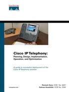
Figure 7-1 shows the proposed voice-mail architecture for XYZ. The Cisco Unity system that is deployed in Unified Messaging mode replaces the Octel voice-mail system in Sydney. In the San Jose location, the Octel voice-mail system will remain. The Seattle and Dallas sites use the existing Octel voice-mail system in San Jose.

Integration between the CallManager cluster in San Jose and the Octel voice-mail system in San Jose is done by using a Cisco Digital Port Adapter (DPA - 7630). The Cisco DPA-7630 communicates with the Octel voice mail system using 24 digital phone lines. DPA-7630 uses the Skinny Client Control Protocol (SCCP) to communicate with CallManager. Because XYZ uses the voice-mail system as a networking service (meaning all employees can network messages to each other via direct addressing or by using voice-mail distribution lists) integration and interoperability between the Octel network and the Cisco Unity environment needs to be maintained. Therefore, use of the Cisco Unity Bridge is necessary in this setup. The communication between the Cisco Unity server in Sydney and the Unity Bridge in San Jose uses a Simple Mail Transfer Protocol (SMTP) connection, and the communication between the Unity Bridge and the Octel system in San Jose is via an analog connection.
The call flow for messages addressed from a Unity-user in Sydney to an Octel-user San Jose is as follows: The voice mail message addressed in the Unity system in Sydney to an Octel subscriber in San Jose, travels via the internal IP network over an SMTP connection and reaches the Unity Bridge in San Jose. The Unity Bridge will then package this voice mail message as an Analog OctelNet message and place a call, via the VG248, to the Octel system in San Jose. This call will go through the DPA (which is the interface between the CallManager and the Octel system) to reach the Octel System and complete the analog networking call.
The call flow for the opposite is similar. When a voice mail message is addressed from an Octel user in San Jose to a Unity-user in Sydney, the Octel System places a call to the Unity Bridge. The call goes from the Octel system ports that are connected to the DPA and reaches the VG248 which houses the analog extensions for the Unity Bridge. The Unity Bridge then repackages the OctelNet messages to an SMTP message and sends it over the internal network to the Unity server in Sydney.
Unity subscribers in the Sydney, Melbourne, and Brisbane sites can access voice-mail messages via their IP Phones, cell phones, or any other external phone. In addition, Unity will activate the message waiting indicator (MWI) on the phone of the related subscriber and process the Outcall notifications to a pager, cell phone, or home phone, whichever is configured by the subscriber. Subscribers can also access voice-mail messages via a web browser and can customize their mailbox settings, such as greetings, Outcall notifications, and so on.
In the Unified Messaging environment, the voice-mail message is delivered to the subscriber in their common (e-mail and voice-mail) inbox.
Unity integrates with AD and heavily relies on the messaging infrastructure. Unity supports Microsoft Exchange 2000 or 2003 and IBM Lotus Notes as the message store. Therefore, understanding the messaging architecture is important when you are designing the Unity system.
A prerequisite for deploying Unity in a Unified Messaging mode is that the AD domain and Exchange 2000/2003 or IBM Lotus Notes environment is set up and working properly. Exchange 5.5 support is not an option with Unity versions 4.0 and above.
Unity can answer calls and take voice-mail messages just like the Octel voice-mail systems that are partially replaced in this case study. The subscriber can retrieve their messages through any of the following choices:
By using the phone
By using Microsoft Outlook
By accessing the Cisco Unity Inbox via the web interface
Note
Because XYZ uses Microsoft Exchange as a message store, use of IBM Lotus Notes is not applicable for this case study.
Unity requires extensions to the AD schema. Unity uses AD to service subscribers whose mailboxes reside on Exchange 2000. Unity does this by extending the schema with the addition of the Unity attributes for the following objects:
User
Group
Contact
Unity Location (newly created object)
Unity Location is a special object that allows Unity servers to identify themselves to other Unity servers in the enterprise. It is used only by Unity servers.
To view the list of attributes added for each object, their values, and the impact on the size of the AD database, use the following URL:
To see the changes made to the AD schema, browse to the directory SchemaLdifScripts on Cisco Unity CD 1, and view the file Avdirmonex2k.ldf. If the extension of the AD schema is not acceptable, deploy a new AD and Exchange environment and deploy Unity as a voice-mail-only solution. After the IT team or the enterprise messaging/directory team is comfortable in extending the schema, it is possible to migrate to Unified Messaging and use the corporate messaging infrastructure.
A key requirement before you design a Unity system and deploy it into a network is to understand the existing AD and messaging architecture (Microsoft Exchange/Lotus Domino). Figure 7-2 shows the AD architecture for XYZ. You can see that XYZ has a single AD forest for the entire organization. From the AD point of view, there are two sites—San Jose and Sydney—each of which has a domain controller (DC) and a Global Catalog (GC) server, as shown previously in Figure 7-1.

As Figure 7-3 shows, the Exchange 2000 messaging architecture for the XYZ San Jose and Sydney sites has Exchange 2000 servers. The San Jose site has three Exchange servers, and the Sydney site has two Exchange servers.

XYZ defined routing groups on a per-site basis, one for San Jose and one for Sydney. Groups of servers running Exchange 2000 form routing groups. Typically, permanent high-speed links connect the servers within the same routing group. A routing group connector connects two different routing groups. Microsoft Exchange uses routing group connectors and Bridgehead servers to route the messages between different routing groups. Bridgehead servers run Exchange 2000 and host routing group connectors.
In the XYZ environment, a message from a user in San Jose to a user in Sydney travels via the routing group connector. Messages between the servers within the same routing group are sent directly from the source server to the destination server using SMTP.
After you understand the AD and messaging architecture deployed at XYZ, the next step is to choose the Unity deployment model. Three types of deployment models are available when deploying Unity:
Centralized—. Unity servers are collocated with the message store servers and the phone system.
Distributed—. Unity servers are not collocated with the message store servers and the phone system.
Hybrid—. This is a mix of the centralized and distributed models. Unity servers can be deployed at a central location and at remote sites that have numerous users.
When choosing the deployment model consider the following factors:
Unity integration with the phone system—. If the integration is analog, such as SMDI, cable length requirements might force you to have Cisco Unity servers collocated with the phone system.
Location of the message store—. If the message store is centralized, place the Unity servers with the message store servers at the same location. To deploy Unity servers in a different location from the message store servers, ensure that there is a LAN connection that connects the locations and that is highly reliable, has less round-trip delay time, and has high bandwidth to avoid synchronization issues.
For XYZ, because the message store servers and CallManager system are in Sydney, deploying Unity servers in Sydney is ideal. A centralized Unity deployment model suits this location because the remote sites in Melbourne and Brisbane have fewer users and do not have significant bandwidth implications. The users at Sydney, Melbourne, and Brisbane access the Unity system in Sydney for their voice mails.
The best practice is to deploy the Unity and Exchange servers on the same subnet in a LAN environment, for the following reasons:
Unity uses Mail Application Programming Interface (MAPI) to communicate with Exchange.
MAPI uses remote-procedure call (RPC) as a transport protocol.
RPC is a chatty protocol, so it can introduce delays over slow-speed links and cause problems while passing through firewalls.
XYZ has an already operational Exchange 2000 environment in its regional hub of Sydney. Therefore, the Sydney data center is the ideal place to deploy the Unity server.
Many organizations rely on networked voice mail as an essential business tool to enable a caller to leave a message if the employee whom they are calling is unavailable to pick up the phone or to send messages directly to another employee’s mailbox. Therefore, the high availability of the voice-mail system is critical.
Clustering is not currently available on the Unity servers. To achieve high availability, deploy Unity servers in active/standby pair, whereby one server is sitting idle until the active one fails.
For XYZ to achieve high availability, it will deploy two Unity servers in Sydney.
As discussed in Chapter 6, “Design of Call-Processing Infrastructure and Applications,” XYZ has good practices in place for securing the CallManager servers. To protect the Unity servers similarly, XYZ plans to do the following:
Install the virus-scanning software and the Cisco Secure Agent (CSA) for intrusion detection on the Unity and Unity Bridge servers.
Apply all Cisco-recommended settings, security patches and operating system service packs to the servers from the moment they become available.
Implement the physical security for the computer room in Sydney where Unity servers are placed.
The procedure to back up the AD forest and the Exchange 2000 environment is already in place in the XYZ network. Add the Unity servers to the list of servers and perform the regular backups. Unlike CallManager software, which bundles the backup utility, Unity does not include a backup utility. Cisco recommends using VERITAS NetBackup software (http://www.veritas.com/).
After every major configuration change to a Unity system, use Disaster Recovery Tool (DiRT), part of the Cisco Unity tools depot, to backup the Unity server database and store the backup data on central file server in Sydney.
The users of XYZ in Australia will be able to access their voice mail via the following methods (see Figure 7-4):

Accessing voice mail using the TUI is the same as accessing voice mail on the Octel system.
By dialing into the Unity server, users can access their voice-mail messages via the IP Phone or via a PBX extension, if Cisco Unity integrates with the PBX. Via this method, users can listen to their voice-mail messages, to the headers of e-mail messages, and to the body of e-mail messages. This method embodies the definition of Unified Messaging.
The default order in which Unity plays the messages to the user is as follows: urgent voice mails, normal-priority voice mails, urgent e-mails, and normal-priority e-mails. This order of access can be changed by the Australian employees of XYZ in Cisco PCA. When a user dials in from their car in the morning, they might want to hear urgent e-mails, before urgent voice mails. This characteristic depends on how the mails are handled in the XYZ environment and what privileges are given to users, based on their role and position in the company.
Listening to e-mails when calling the voice mailbox over the TUI requires the license for text-to-speech (TTS) sessions on the Unity servers.
All users from XYZ will also have their mobile phone numbers configured in Unity as an alternate extension (as discussed later, in the “Customizing the Cisco Unity System” section). As a result, it will be easy for them to call their inbox when they are not at their desk phone in the office. The system will recognize the calling line ID (CLID) from the mobile phone and immediately prompt the user for their personal identification number (PIN) rather than his mailbox number.
Cisco Unity also provides a GUI so that you can access voice-mail messages from your desktop/PC by using Cisco Personal Communications Assistant.
The Australian users will also be able to access their messages via the Cisco Unity Inbox, a web application that is part of Cisco PCA. The Cisco Unity Inbox allows users to browse to a web page and retrieve their messages, greetings, and so on. Users can also use this web page to change their alternate greetings.
Cisco PCA enables Unity subscribers to access the following two applications in Unity:
Cisco Unity Assistant (also called Active Assistant [AA]), which lets subscribers do the following:
— Customize how they and callers to their mailbox interact with Unity by phone
— Personalize Unity settings, including their recorded greetings and message-delivery options
— Set up message-notification devices and create private lists
Cisco Unity Inbox (formerly known as Visual Messaging Interface [VMI]), which allows subscribers to listen to, compose, reply to, forward, and delete voice-mail messages. Cisco Unity Inbox is a licensed feature.
To access Cisco PCA, subscribers use the following URL from the Internet Explorer web browser:
http://IP_Addr_Unity/ciscopca
Figure 7-5 shows the Cisco PCA application.

It is also possible to use Microsoft Outlook to read e-mails, receive voice mails as a WAV attachment, and retrieve voice mails by using View Mail for Outlook (VMO). VMO is a plug-in application, added to the user’s PC, that enables the user to retrieve voice mails from their laptop or desktop.
With this VMO component added to Outlook, it is possible to receive a voice mail from a peer and reply as a voice mail to the originating party. Without VMO, this reply is always sent as a WAV file attachment in an e-mail. Also, the originating party who receives the reply will not be able to handle this message as a voice mail (in Unity) without VMO.
The advantages of VMO are seen only when both the sender and receiver of the voice mail use Unity system. For XYZ, because in US location, users have Octel system and Australian users have Unity system, whenever a user from Australia sends a voice mail to a user in San Jose using VMO, San Jose user will always receive the voice mail as an e-mail with a WAV attachment.
Another method of accessing the voice messages is through OWA. To access the messages, type the following URL from your Internet Explorer:
http://IP_Addr_of_Exchange_Server/exchange
When you use OWA, voice mails are shown as e-mails, with the actual voice message as a WAV attachment.
As discussed in the preceding sections, XYZ uses Exchange 2000 as the e-mail system for all the users in Australia. The AD forest (domain controller/Global Catalog) is fully deployed and operational in Australia. A stable working AD domain and Exchange 2000 network is the key to the success of this Unified Messaging rollout.
For the purpose of this case study, the Unity system replaces the Octel voice-mail system in Sydney. In the San Jose location, the Octel voice-mail system will stay in place and integrate with the CallManager cluster in San Jose.
Because XYZ already has a stable infrastructure, the Unity design and deployment for XYZ does the following:
Uses the existing Windows 2000 domain infrastructure to house the Unity servers
Uses the existing Exchange 2000 messaging infrastructure to service as a back-end message store
Requires installation of Unity on a separate server and not on any of the existing AD/Exchange infrastructure
The hosting team within XYZ feels comfortable extending the scope of Exchange 2000 to accomplish a Unified Messaging setup. In addition, the additional MAPI connections to the server are not expected to cause issues. MAPI functions as the primary means by which Exchange and Outlook communicate with one another.
To XYZ, whether San Jose users are also using Exchange 2000 or are still using another e-mail infrastructure with plans to move to Exchange in the future before implementing Cisco Unity is unimportant, because San Jose users will continue to use their current Octel voice-mail system. The e-mail system that is used in San Jose is important only after San Jose users start to move to Unity/Unified Messaging. For now, the voice-mail environment is not affected if San Jose users are on Exchange 2000.
The Unity server can store the messages either in G.711 or G729a format. Selecting the codec format depends on the availability of hardware resources such as hard disk sizes and hardware transcoder devices if the IPT network that is deployed uses multiple codecs. Based on XYZ’s requirements, G.711 is the choice of codec to store messages on the Unity server.
Before you size the hard disk, you need to study the use of the existing voice-mail system. Investigating the system statistics from the Octel messaging system in Sydney reveals that it is sufficient to provision the Sydney user mailboxes to store 1 hour’s worth of voice messages. According to Table 7-1, G.711 uses 8 KB of hard disk space to record a 1-second voice message. To store voice messages of up to 1 hour (3600 seconds), you need approximately 3600 × 8 KB, which is 28.8 MB for each Exchange mailbox.
Table 7-1. Unity Hard Disk Sizing Guide
Users | Messages | Codec Type and Sampling Rate | Average Message Size in Seconds | Storage Size for G.711 in Bytes |
|---|---|---|---|---|
1 | 15 | G.711 @ 8 Kbps | 40 | 4,800,000 |
10 | 15 | 40 | 48,000,000 | |
100 | 15 | 40 | 480,000,000 | |
500 | 15 | 40 | 2,400,000,000 | |
1000 | 15 | 40 | 4,800,000,000 | |
1500 | 15 | 40 | 7,200,000,000 | |
2000 | 15 | 40 | 9,600,000,000 | |
5000 | 15 | 40 | 24,000,000,000 | |
7500 | 15 | 40 | 36,000,000,000 | |
10,000 | 15 | 40 | 48,000,000,000 | |
Users | Messages | Codec Type and Sampling Rate | Average Message Size in Seconds | Storage Size for G.729a in Bytes |
1 | 15 | G.729a @ 8 Kbps | 40 | 600,000 |
10 | 15 | 40 | 6,000,000 | |
100 | 15 | 40 | 60,000,000 | |
500 | 15 | 40 | 300,000,000 | |
1000 | 15 | 40 | 600,000,000 | |
1500 | 15 | 40 | 900,000,000 | |
2500 | 15 | 40 | 1,500,000,000 | |
5000 | 15 | 40 | 3,000,000,000 | |
7500 | 15 | 40 | 4,500,000,000 | |
10,000 | 15 | 40 | 6,000,000,000 |
Note
If you cannot obtain the statistics from the existing voice-mail system or no voice-mail system existed before, use Table 7-1 to calculate the hard disk size required.
XYZ corporate policy is to retain the deleted voice messages for up to 7 days. To account for this, the storage requirements per user mailbox are expanded to 56 MB.
Taking into account the 550 employees that use the Unity system in Sydney, Melbourne, and Brisbane, the additional requirement for voice-mail storage increases to a minimum of approximately 56 MB × 550 = 30 GB. From the current standards regarding disk space, this is not an issue for XYZ, because it has performed decent sizing of its Exchange 2000 environment from the beginning.
To accommodate the additional storage requirements to store the voice messages, the Exchange system administrator of XYZ will expand the storage limits on an individual mailbox basis to reflect these previously mentioned requirements.
Using the class of service (CoS) feature in Unity, a user or group of users can get additional hours of storage to retain their voice mails. You can define a separate CoS with more hours and assign this CoS to the users who need extra storage.
The number of Unity ports in a system determines the number of simultaneous callers who can call into the Unity system. Because ports or sessions are licensed components in Unity, XYZ has to pay a license for each. Therefore, proper sizing of the Unity ports/session is important to avoid paying for unneeded ports/sessions.
There are two different approaches to doing port sizing. The first approach, adopted by XYZ, is to use a port-to-user ratio of 1:20 to determine the number of ports or sessions required on the Octel voice-mail system. Using the same approach, for 550 users (including the users at Melbourne and Brisbane), 28 ports are needed on the Unity server. In Unity, you also need a few ports exclusively reserved for lighting the MWI on the handsets of IP Phones and a few ports exclusively reserved for Outcall notification purposes. Therefore, after reserving two ports each for these purposes, XYZ requires a Unity system with 32 port/sessions.
In the second approach to port sizing the Unity system, the number of ports required depends on the following parameters:
Average calls per hour to the voice-mail system
Average length in seconds
If you have an existing voice-mail system, these parameters are available in the system reports. After you have these parameters, to calculate the number of ports required, use the following formula:
As an example, assume that a customer has on average 200 calls per hour into the system with an average length of 4 minutes (240 seconds) for voice-mail messages. Based on this information, this customer requires a Unity system with 13 ports. Taking into consideration the additional ports that must be reserved for MWI and Outcall notifications and future expansion possibilities, the customer could deploy one primary Unity server with 20 ports and one standby Unity server with 20 ports for failover situations.
Various Cisco-certified hardware platforms are available to run the Unity software. Selection of the hardware depends on the following factors:
Number of ports or sessions
Number of users
Number of TTS sessions
Message store location
—An external message store requires less hard drive capacity on the Unity server.
—A message store on the Unity server requires more hard drive capacity.
Number of slots required on the Unity system
Data protection requirements
Refer to the following URL to obtain the complete Cisco Unity Supported Platforms List:
XYZ is opting for the higher-end servers because they offer more redundancy. The MCS-7845I has a dual power supply, and each of the power supplies is on isolated, redundant circuits that can handle a minimum of 350W.
Because the Sydney office is a regional hub site, it has good backup processes in place and usually stores the backups on a network backup server. That is why the servers do not need a DAT tape drive to perform backups.
System administrators commonly implement redundant array of inexpensive disks (RAID) to provide a reliable, redundant means of protecting critical data on a server. RAID is a method whereby information is spread across several disks, using techniques such as disk striping (RAID level 0) and disk mirroring (RAID level 1) to achieve redundancy, lower latency, and higher bandwidth for reading and writing and recoverability from hard-disk crashes. Six different types of RAID configurations are “available”, RAID 1 is the most inexpensive method to protect the data.
At XYZ, Unity servers will use a RAID 1 array to protect the data, because voice-mail messages are essential to users and often contain sensitive and important information.
The prerequisite for the Unified Messaging rollout in this case study is a fully established and working AD forest and Exchange 2000 organization. For Unified Messaging deployment using Unity, Cisco does not ship licenses to use Microsoft Exchange server software or Client Access Licenses (CALs) for accessing the Microsoft Exchange server.
Count the Microsoft Exchange 2000 server software and CAL against the corporate software licensing agreement that XYZ has with Microsoft. XYZ’s corporate messaging team should verify this with the vendor management office to ensure full licensing.
If numerous Unity servers and bridges are connected to the network, a specific naming convention has to be put in place that clearly identifies the function and location of the server. This is just a naming convention and should be used only to make future troubleshooting tasks easier.
With the design steps covered so far, enough information is available to decide on the required number of Unity licenses. Each Unity server will have its license configured as follows. XYZ must submit a license request to Cisco Systems with the MAC address of each server in the node.
Unity version 4.0.3
600 Unified Messaging for Exchange user licenses
600 VMI or Unity Inbox user licenses
16 RealSpeak TTS sessions
16 additional language licenses if not all subscribers on the Sydney Unity will use the same language
Unity Bridge 4 port license
Failover enabled (Product ID: UNITY-FOVRSVR33-UP)
Note
You obtain these license files directly from Cisco Systems. Go to the Cisco Unity Licensing FAQ site to learn how to obtain the licenses for the Unity system:
Refer to the following URL to get more information on how licensing works in Unity:
The Cisco Unity license ties to the MAC address for the network interface card (NIC) in the Cisco Unity server that Cisco Unity will be run on. To find the MAC address on the Unity server after installing the operating system but before installing Cisco Unity, follow these steps:
On the server where Cisco Unity will be installed, on the Windows Start menu, click Programs > Accessories > Command Prompt.
In the Command Prompt window, enter ipconfig/all and press Enter.
Select the value for Physical Address and press Enter (This copies it to the Windows clipboard.) For multiple MAC addresses, select the first one only.
Paste the value of the MAC address and remove the hyphens (for example, 00-A1-B2-C3-D4-E5 should be entered as 00A1B2C3D4E5) when submitting for a license to Cisco.
If you are deploying Unity with dual NICs, use the virtual MAC address when obtaining the license file.
If you replace the NIC on the servers, you have to resubmit the request to obtain the new license files.
As discussed in the “Microsoft Active Directory and Exchange” section earlier in this chapter, extending the AD schema is an important and mandatory task prior to installing Unity or the Unity Bridge. The extension of the AD schema allows a proper installation and integration of the Unity and Bridge systems.
Active Directory supports the use of LDAP Data Interchange Format (LDIF) scripts to extend the schema. Therefore, you need to run on the AD DC the executable called ADSchemaSetup.exe, located on the Unity installation DVD/CD-ROM, and the LDIF script files. Although there are two DCs, one in San Jose and one in Sydney, there is only one common schema. When you run the ADSchemaSetup.exe program, shown in Figure 7-6, the schema is extended and Unity-specific attributes are added into the AD. When you run ADSchemaSetup.exe, check the Exchange 2000 or Exchange 2003 Directory Monitor and Exchange 2000 or Exchange 2003 Bridge Connector check boxes to extend the schema required by Unity and the Unity Bridge.

Follow the guidelines exactly as addressed in the Cisco Unity Installation Guide (discussed next) and Cisco Unity Bridge Installation Guide, both of which are available on Cisco.com. A domain administrator who has access rights to the Active Directory (for example, as a member of the AD Schema Admin group) must perform the schema extension operation.
The steps to install Cisco Unity are listed in the Cisco Unity Installation Guide on Cisco.com:
You should ensure that you fulfill the physical requirements of the Unity server before you install Unity. The IT team of XYZ has verified the following with the employees who are responsible for the computer room and buildings in Sydney:
Enough free rack space is available.
Data connections are available.
The UPS can handle the additional load.
On one of the Exchange 2000 servers in Sydney, the Cisco Unity Internet Voice Connector (IVC) has to be installed. It is up to the Exchange 2000 administrator to determine which server can best handle this functionality. In the case of XYZ, this is the [email protected] server, which handles all user accounts for Australia.
As mentioned earlier, the Unity server will handle only messages that are using the G.711 codec. If XYZ discovers after installation that the G.729a codec is required over the WAN for capacity reasons, XYZ will rely on hardware transcoding in DSP farms to perform these conversions. You have to take into account that too much iteration between the G.711 and G.729a codecs can eventually degrade the voice quality. As a rule of thumb, try to limit the number of conversions of a single message to two.
The staff who is responsible for the operation and maintenance of the Unity server will use the administrator account of the Unity server. This account is used to install the server and allows all maintenance activities on the server.
The first-line support staff will get base access on the servers to administer subscribers. The administrator passwords are distributed only to senior Unity support staff.
End users can interact with the Unity system by using their phone, Outlook client, or Cisco PCA. When using Cisco PCA, the user credentials are sent in clear text across the network when Secure Sockets Layer (SSL) protocol is not enabled on Unity. In case of XYZ, as an added security measure, Unity will be set up to support the SSL protocol to avoid the security risk.
For security reasons, the administrator of the Unity server will not use the same account and password to log in to Cisco PCA as he uses to log in to the administration web pages.
The official business language within XYZ is English. Two language packages will be installed. U.S. English (Windows locale is required) and Australian English. The Australian subscribers will be configured for the Australian English option.
The TTS language will be based on the user’s location. Because all the Unity users in this case study are based in Australia, only one option will be selected for now.
XYZ requires voice-mail integration at two locations:
The CallManager in Sydney
The Octel system with CallManager in San Jose
Unity integrates seamlessly with CallManager by using SCCP. The next few sections discuss the configurations required to complete the Unity integration with CallManager.
Configuring partitions and CSS in CallManager
Changing service parameters in CallManager
Defining MWI on and off numbers in CallManager
Defining voice-mail ports in CallManager
Defining the voice-mail pilot number in CallManager
Defining the voice-mail profile in CallManager
Reserving ports for MWIs and outcall notifications in Unity
Making changes to the Octel access numbers
Configuring the AutoAttendant functionality in Unity
This section discusses the design of partitions and the calling search space (CSS) for voice-mail ports, MWI On/Off numbers, and voice-mail pilot numbers. Because voice-mail ports appear to CallManager as any other IP phone, the concept of partitions and CSS also applies to these ports. Unity uses voice-mail ports for two purposes:
To turn on and off MWI lamps on the phones
To send call notifications
Tables 7-2 and 7-3 list the partitions and CSS configurations, respectively, required on IP Phones, MWI On/Off numbers, and voice-mail ports in the Sydney CallManager cluster.
Table 7-2. List of Partitions
Partition Name | Description |
|---|---|
Pt_allphones | All IP Phones’ DN[1]s are included in this partition |
Pt_mwi | MWI On/Off number partition |
Pt_vmpilot | Voice-mail pilot number partition (first voice-mail port) |
Pt_vmpilot1 | Partition that includes all other voice-mail ports |
Pt_local | Partition that contains route patterns that provide local access |
[1] Directory Number | |
Table 7-3. List of Calling Search Spaces
CSS Name | List of Partitions | Description |
|---|---|---|
Css_local | Pt_allphones Pt_mwi Pt_vmPilot Pt_local | IP Phones that have access to local calling |
Css_mwi | Pt_allphones | CSS on MWI On/Off numbers |
Css_vmports | Pt_mwi Pt_allphones Pt_local | CSS on the voice-mail ports |
Css_CFBCFNAvmports | Pt_vmpilot1 | CSS for the Call Forward Busy (CFB) and Call Forward No Answer (CFNA) on the voice-mail ports |
By default, CallManager hops to a maximum of 12 voice-mail ports. Because the Unity system at XYZ has 32 ports, the following two service parameters for CallManager service have to be set on the Sydney CallManager cluster accordingly. To access the service parameters, from the CallManager Administration page, choose Service > Service Parameters > CallManager Service.
Set the Voice Mail Maximum Hop Count to 28 (because XYZ has a maximum of 32 ports, the last 4 of which are assigned to MWI and Outcall notifications).
Set the Advanced CallForward Hop Flag to True (to immediately jump to the first available port).
Both parameters are cluster-wide parameters.
An MWI lamp lighted on the IP Phone indicates to the user that new voice-mail messages are waiting in the mailbox. Before you define the MWI On/Off numbers, it is helpful to understand how Unity and CallManager turn on/off MWI lamps on the phones. To turn on the MWI for extension 6200, for example, Unity goes off hook on one of its ports and dials the MWI On number. However, Unity sets the calling party extension as 6200. CallManager looks at the calling party number and lights the lamp for extension 6200. Similarly, to turn MWI off, Unity dials the MWI Off number.
Hence, you need one MWI On and one MWI Off number per CallManager cluster. To define these numbers in the CallManager from the CallManager Administration page, choose Feature > Voice Mail > Message Waiting. On this page, you have an option to configure a partition and CSS for MWI On and Off numbers. Table 7-4 shows the configuration settings for the MWI On/Off numbers in the Sydney CallManager cluster.
Table 7-4. MWI On/Off Settings
MWI Number | MWI Type | Partition | Calling Search Space |
|---|---|---|---|
5600 | ON | Pt_mwi | Css_mwi |
5601 | Off | Pt_mwi | Css_mwi |
The CSS on the MWI On/Off numbers helps CallManager to determine which phones’ MWI to turn on and off. Assume that two phones with the same directory number 6200 exist, one in Partition_X and the other in Partition_Y. If the CSS for the MWI On/Off numbers contains Partition_X alone, it can turn on and off the MWI for the phone with extension 6200, which is in Partition_X. The opposite is true if the CSS includes only Partition_Y. If the CSS contains both partitions, the partition order that is defined in the CSS comes into effect, because there is a tie in the pattern, which in this case is 6200. Hence, the rule is that the CSS on the MWI On/Off numbers should include the partitions in which IP Phone directory numbers reside.
As mentioned earlier, Unity goes off hook on one of the voice-mail ports and dials the MWI On/Off number to turn on or off the MWI lamp. This means the following:
The CSS that is configured on the voice-mail ports should include the partition in which MWI On/Off numbers reside. Without this, Unity cannot set the MWI On/Off for the phones.
The CSS that is configured on the IP Phones should also include the partition in which MWI On/Off numbers reside.
To configure the voice-mail ports in CallManager, you can use the Voice Mail Port Wizard that is available specifically for Unity. To access this wizard from the CallManager Administration page, choose Feature > Voice Mail > Cisco Voice Mail Port Wizard.
As stated in the “Sizing Unity Ports and Sessions” section earlier in this chapter, the Unity system at XYZ requires 32 ports. Hence, the number of ports that has to be configured on the CallManager is 64: 32 for the primary Unity server and 32 for the failover Unity server. Each set of ports matches to a voice-mail pilot number. The primary Unity server uses the same voice-mail pilot number as used in the past for the Octel system in Sydney, which is 5000.
Table 7-5 shows the voice-mail port settings required in the Sydney CallManager cluster. The table shows samples that you can follow for all 32 ports.
Table 7-5. Voice-Mail Port Settings
Partition | Device Pool | Calling Search Space | Directory Number | CFB | CFNA | |
|---|---|---|---|---|---|---|
PriUM-VI1 | Pt_vmpilot | DP-SYDNEY | Css_vmports | 5000 | 5001 | 5032 |
PriUM-VI2 | Pt_vmpilot1 | DP-SYDNEY | Css_vmports | 5001 | 5002 | 5032 |
PriUM-VI28 | Pt_vmpilot1 | DP-SYDNEY | Css_vmports | 5027 | 5000 | 5032 |
PriUM-VI31 | Pt_vmpilot1 | DP-SYDNEY | Css_vmports | 5030 | 5000 | 5000 |
PriUM-VI32 | Pt_vmpilot1 | DP-SYDNEY | Css_vmports | 5031 | 5000 | 5000 |
SecUM-VI1 | Pt_vmpilot1 | DP-SYDNEY | Css_vmports | 5032 | 5033 | 6002 |
SecUM-VI28 | Pt_vmpilot1 | DP-SYDNEY | Css_vmports | 5058 | 6002 | 6002 |
SecUM-VI31 | Pt_vmpilot1 | DP-SYDNEY | Css_vmports | 5062 | 5032 | 5032 |
SecUM-VI32 | Pt_vmpilot1 | DP-SYDNEY | Css_vmports | 5063 | 5032 | 5032 |
Note the following from Table 7-5:
The CFNA setting for all the voice-mail ports on the first Unity server is configured with the directory number of the first voice-mail port on the secondary Unity server (5032). A CFNA situation arises only if the Unity server is not responding, which indicates a failure in the system and that the call should be forwarded to the secondary Unity server.
The directory number for the first voice-mail port is 5000. In Sydney, the DID number to access the voice mail from the public switched telephone network (PSTN) is 555-6000. A CTI route point/CTI port will be created and Call Forward All (CFA) will be set to forward to DN 5000. The Unity call-routing rules will be modified as discussed in the “Multiple Directory Handlers” section later in this chapter to play the opening greeting for the Sydney office.
The voice-mail pilot number on the primary server is in a different partition compared to the other voice-mail ports. The partition pt_vmpilot1 is not visible to any other device, which means that users cannot dial these ports directly from their phones. This gives the impression of a single voice-mail number to the whole system. The partition pt_vmpilot1 will only be part of the CSS that is configured on the CFB and CFNA on the voice-mail ports.
The CFB and CFNA on the last two voice-mail ports on the secondary server are set to forward to the operator (60002). In Table 7-5, Unity Ports 1 to 28 (thatr is. ports PriUM-VI1 through PriUM-VI28 on the primary server and ports SecUM-VI1 through SecUM-VI28 on the secondary server) are used for accessing the voice mail. The last four ports on each server are used for the MWI notifications.
When defining the Unity voice-mail ports in CallManager, you have an option to configure the CSS at the device level and at the voice-mail port directory-number level. At the directory-number level, you can configure the partition in which the directory number resides.
You must set the access restrictions on the voice-mail ports by assigning a restricted CSS in CallManager for voice-mail ports, to avoid the expensive telephone charges. The best practice in configuring the voice-mail ports is to limit the CSS of these ports to allow national calls but to block international dialing. This also avoids toll fraud via the voice-mail system that can occur due to message notifications (user configurable) being sent to international numbers.
It is better to keep the restrictions centralized on the CallManager. That way, you need to make sure only that they are really applied on the CallManager ports; otherwise, you are going to open a door for toll fraud. On the other hand, it is not a good design to build part of the restrictions into the Unity configuration and another part into the CallManager dial plan. To summarize, the following are the rules for the CSS and partitions for the voice-mail ports:
The CSS for the Unity voice-mail ports should contain the partition in which the MWI On/Off numbers reside.
If you would like Unity to notify external phone numbers, the partition to reach the external numbers should also be part of this CSS.
To enable users to call the voice mail directly to log in to their mailbox or press the * key to call another extension, the CSS on the line or the device should include the voice-mail ports.
The voice-mail pilot number is what the phone dials when the user presses the Messages button on the Cisco IP Phone or forwards the call to voice mail. CallManager uses the CSS that is defined for the voice-mail pilot numbers when the phone is forwarded to voice mail. If the CSS on the voice-mail pilot number is set to None and the voice-mail port directory numbers are configured to be in a partition, the forward operation will fail even if the line can call the voice-mail directory numbers.
To configure the voice-mail pilot from CallManager Administration, choose Feature > Voice Mail > Voice Mail Pilot. Table 7-6 shows the configuration settings for the voice-mail pilot number in the Sydney CallManager cluster.
The last step is to configure a voice-mail profile. To access the configuration page, from CallManager Administration, choose Feature > Voice Mail > Voice Mail Profile. The voice-mail profile is the link between the phone configuration and the voice-mail pilot. Each voice-mail pilot is assigned to a voice-mail profile. The voice-mail profile is in turn assigned to each line or directory number on the phone. Table 7-7 shows the configuration settings for the voice-mail profile in the Sydney CallManager cluster.
Some ports on the Unity system must be configured exclusively for the MWIs. These ports will be able to send a message to CallManager indicating when to turn off or on the MWI lamp on the handset of IP Phones. In addition, these ports will allow for notifications when the users of XYZ receive new messages. Users can choose the time intervals and type of messages (normal, urgent, and so on) for which they want to be notified.
Some changes are required in the Octel system with the introduction of the Unity server in Sydney and the Unity Bridge in San Jose. Before the introduction of Unity in the network, if a user in San Jose addressed a message to a user in Sydney, a digital (over TCP/IP) communication occurred between both Octel systems to get the messages across (using digital OctelNet). In addition, as a failover or backup, there was an analog communication whereby the Octel system in San Jose would call the Octel system in Sydney, and the messages would be delivered via the analog OctelNet protocol.
The phone numbers used for communicating the analog OctelNet messages from San Jose now have to be directed to the Unity Bridge in San Jose instead of the destination in Sydney. The reason for this redirection is that the analog OctelNet destination is now the Unity Bridge in San Jose instead of the Octel system in Sydney. As a result, the Octel voice-mail administrator has to change the voice-mail access number in the San Jose server. For the users, nothing changes; a translation pattern will be in place to translate the local Sydney number to the first Unity port.
Because the Octel system in Sydney offers integrated AutoAttendant (AA) functionality, you need to design the Unity system with similar functionality. The requirement for this feature to work properly is a uniform dial plan, which means that every user who has a mailbox on this Unity system must have a unique extension number within the dialing domain. The easiest way to think about this is to compare the Unity port with a regular IP Phone. As long as the extension number assigned in Unity to the subscriber redirects the call to the subscriber IP Phone, the AA feature will work fine.
Because XYZ has a unique four-digit extension number for every subscriber in Australia, this functionality will be available upon activation of the Unity server without additional programming. Also, because everybody who has a voice-mail account on the Sydney Unity server has a unique four-digit extension number, only one dialing domain will be configured on the Unity server.
XYZ will also verify that the Unity server is within the acceptable boundaries regarding jitter and delay in relation to all users and applications. If an end user picks up the phone and dials the Unity main number, they can listen to messages, record greetings, and perform other functions. The maximum delay between the user’s IP Phone and the Unity system must be within the 150-ms boundary. Because both the Unity server and the CallManager cluster are based in Sydney, delay and jitter are not issues.
The built-in AutoAttendant and the stringent jitter and latency requirements offer an additional advantage. Because the Brisbane users for example, do not have DID number, they have to rely on an AA solution. In this directory, they only want to find the Brisbane users.
Therefore, a call to the AA number in Brisbane is forwarded to the Unity system in Sydney over the WAN link. Refer to the “Remote-Site WAN QoS Design” section in Chapter 5, “Design Phase: Network Infrastructure Design,” to understand the necessary QoS configurations that have to be made for this forwarding to be successful and offer a good voice quality. The calling party connects to the AA in Sydney and Unity system guides the caller through the menu prompts. Based on the user input, Unity system will release the call to the corresponding called party in Brisbane. This avoids the need for a dedicated AA in the other Australian offices. You have to make sure that the necessary bandwidth and failover mechanism are in place via the PSTN.
Note
Another possibility for small remote offices is to use Cisco Unity Express (CUE) and the built in AA functionality. This is currently a standalone solution, which can be seen as a local answering machine. In combination with the Tool Command Language (Tcl) IVR on the Cisco IOS gateways, it is possible to offer local scripting if the WAN does not have enough capacity available.
The type of communication, analog or digital, determines the integration type used between the CallManager and the Octel system. In its San Jose location, XYZ plans to maintain its existing analog integration between the Lucent time-division multiplexing (TDM) PBX and the voice-mail system.
There are three different ways to integrate the CallManager with the Octel voice-mail system in an analog fashion:
Use SMDI between CallManager and the Octel voice-mail system
Use a VG248
Use digital integration with Digital Port Adapter (DPA)
SMDI integration is required if you want to continue to offer existing features and functionalities to the users when they migrate from the Lucent TDM PBX to the CallManager. In fact, this SMDI integration will make it possible for the users to see no change with regards to their voice mail when they move from a Lucent phone to a Cisco IP Phone. This is, of course, only the case when their mailbox stays on the TDM system and is not converted to a Unity mailbox.
When using SMDI integration, there is a serial cable between the CallManager and the serial port (RS-232) of the Octel system. The analog ports used to transfer the voice traffic between both systems can be provided by using a router that has analog ports. The disadvantage of this type of integration is the physical cable between the CallManager and the voice-mail system, as shown in Figure 7-7. If the CallManager at which this physical cable terminates experiences a problem, the voice-mail system will be disconnected from the CallManager. In addition, physical requirements (such as, the length of the serial cable) are related to this setup.

VG248 communicates using SCCP with the CallManager cluster. VG248 offers failover and redundancy, like any other SCCP device. This method of integration does not require involvement from the Octel voice-mail system either. It is possible to simply unplug the cables from the voice-mail system and plug them into the VG248—no recabling is required.
Figures 7-8 and 7-9 show how this integration looks and how to scale this integration further, respectively. Another possibility is to implement a hybrid solution whereby the CallManager and TDM PBX can coexist and use the same voice-mail system. However, XYZ has chosen to do a full transition to the IP-based PBX systems in San Jose.


There is also a digital integration method available between the CallManager and the Octel voice-mail system by using the Digital Port Adaptor 7630 (DPA-7630), as shown in Figure 7-10. The functionality of this device is comparable to the VG248, because it translates SCCP messages to DCP, the proprietary protocol used by the digital Lucent handsets. The digital integration method has the same advantages as the VG248 related to failover and physical requirements.

XYZ has chosen the digital integration method to integrate the Octel voice mail system in San Jose with the San Jose CallManager cluster because XYZ has the required hardware on the Octel voice mail system to support the integration with DPA-7630.
The Networking feature in Cisco Unity is used to deliver the messages from a Unity server to a target voice-mail system and from the target voice mail system to Unity server. The target voice-mail system could be another Unity server or any other supported vendor’s voice mail system. The following networking options are discussed in the next few sections:
Digital Networking allows messaging between two or more Unity servers provided they share the same global directory.
Because XYZ’s setup has only one Unity server site (Sydney), it is not necessary to address specifically the Unity networking connections between different Unity servers. In brief, if in the future the San Jose site is also converted to Unity, the digital networking can be performed by the Exchange 2000 organization, by the message transport agent (MTA). This is true if both Unity servers are part of the same AD forest.
Bridge Networking allows messaging between the Unity server and Octel voice-mail system by using Cisco Unity Bridge. In the current case study, the Unity system in Sydney has to be able to communicate with the Octel system in the San Jose site. Unity Bridge will network the two systems.
Unity also supports the Audio Messaging Interchange Specification–analog (AMIS-a) networking protocol, which can be made available on the Octel system depending on the options purchased for the Octel system. However, AMIS-a offers fewer features than the analog OctelNet protocol. In fact, the analog OctelNet protocol is an improved version of AMIS-a. Avaya (or better, the part of Avaya that used to be Octel before Avaya acquired them) originally developed the analog OctelNet protocol as a common denominator between the Aria and Serenade systems. It then made improvements based on the AMIS-a foundation. The Aria platform is a voice-mail product line from Avaya that is used mainly in the United States, whereas the Serenade product line is used mostly in Asia Pacific and Europe.
One example of this feature difference between AMIS-a and Analog OctelNet is the use of multiple/single-source delivery. When a message is sent using AMIS-a between two voice-mail systems and the message has to reach five different recipients at the destination site, the message is sent across (played back between both systems) five times. This is known as multiple source delivery. With the analog OctelNet protocol (also used by the Unity Bridge), single source delivery is used—namely, the message is sent over only once and is distributed accordingly in the destination voice-mail system. Signaling between both systems is carried as DTMF signals over analog phone lines.
Another possibility for voice-mail networking is the Voice Profile for Internet Messaging (VPIM) networking protocol. VPIM allows communication between voice-mail systems to exchange voice and fax messages over the Internet or any TCP/IP connection. VPIM is based on SMTP and the Multipurpose Internet Mail Extensions (MIME) protocol.
VPIM can be used under different circumstances. In certain voice-mail networks, an Intuity Interchange is present. This Interchange product was developed by Avaya and is in fact a protocol converter to link voice-mail systems from different vendors. As a result, these disperse systems can look as one voice-mail network with limited functionality. An example of this limited functionality is the forwarding of messages between two systems from different vendors. Both Unity and Intuity Interchange support VPIMv2.
Another use of VPIM is to integrate Unity and another vendor’s voice-mail system that supports the same flavor of VPIM. This allows messages and some other advanced features to be exchanged between two systems.
VPIM can also be used between Unity systems that do not share the same AD and Exchange 2000 infrastructure. In this case, VPIM can be a solution to network these different systems together, which makes it look like one virtual voice-mail system to the users. The directory synchronization is still a manual process, but that is no different from directory synchronization in AMIS-a or Unity Bridge. In earlier releases of Unity, where VPIM was not available, SMTP could be used to bridge two Unity systems located in different AD forests and Exchange 2000 organizations. For every possible destination subscriber on the other system, an Internet subscriber account had to be defined in the local Unity server. Per definition, an Internet subscriber does not have a mailbox in the Exchange 2000 server of the organization that this Unity server integrates. The users do have an entry in the AD forest, which identifies them as Internet subscribers. This entry can hold information such as spoken name, greetings, and so on.
As previously discussed in the “Bridge Networking” section, Cisco Unity Bridge acts as a networking gateway between Cisco Unity and an Octel system on an Octel analog network. This case study addresses the use of the Unity Bridge as a means to allow users to move to a Unity system without having to lose their voice-mail networking capabilities. This section discusses the following topics:
Figure 7-11 depicts the logical deployment architecture with the Unity Bridge for XYZ. The Unity Bridge will allow messaging between the Unity server in Sydney and the Octel system in San Jose via the analog OctelNet protocol. The Unity Bridge acts as a networking gateway between Unity and the Octel system, and it allows the systems to exchange voice messages. Messaging between the Unity server in Sydney and the Unity Bridge in San Jose is carried over the internal network using a digital networking protocol, which is based on the VPIM protocol, with proprietary extensions.

Messaging between the Octel system and the Unity Bridge in San Jose happens using the analog OctelNet protocol. It does not matter whether the Octel system is an Aria platform or a Serenade platform, because the analog OctelNet protocol is the same for both product lines.
Because the communication between the Unity Bridge and the Octel server is analog (in other words, phone calls with DTMF signaling), it is recommended that you keep the connection between them as short as possible. Because the Unity Bridge talks to the Unity server via TCP/IP, distance is not a concern between San Jose and Sydney. In addition, you can administer the Unity system from a web browser via HTTP. Therefore, to avoid possible problems such as DTMF distortion because of a transatlantic analog connection, it is better to place the Unity Bridge in San Jose than in Sydney.
The analog OctelNet protocol works comparably to the AMIS-a standard. An analog phone call is placed to transfer the messages between the servers. Upon answering the incoming call, DTMF handshaking occurs while determining the call is an analog OctelNet call.
The major element in this handshaking is the serial number of the system. When the serial number of the destination system does not match the serial number in the database of the originating server, the call is disconnected. That is why it is important to collect the serial number of the Octel voice-mail system in Sydney and assign the same serial number to the Unity Bridge. Reprogramming of this parameter is not needed in the Octel system in San Jose.
After this verification, both systems start the signaling for the message exchange. Both systems send, receive, and confirm the existence of certain mailboxes on their respective systems. The message is played back from the originating server to the destination server.
Because XYZ has only a single Unity Bridge in San Jose, using a Unity Bridgehead server as a central management entity is not an advantage. If XYZ had to administer a whole range of Bridges, the use of the Bridgehead could simplify the design.
Note
Unity and Exchange both use the term Bridgehead server. An Exchange Bridgehead is a route point for routing messages between route groups within an Exchange organization. Typically, this is between different sites of an organization. A Unity Bridgehead is a single place to maintain bridge locations, bridge subscribers, and distribution lists.
Unity Bridge software runs on a separate and dedicated platform. For the list of supported hardware platforms for Unity and Unity Bridge, refer to the following URL on Cisco.com:
As shown in Figure 7-11, the communication between the Unity Bridge and the Octel system in San Jose happens via an analog connection. On the Unity Bridge server, these analog ports are provided by the Brooktrout cards, which you need to order specifically. Refer to the following URL for ordering information on these cards:
The ports on the Brooktrout cards work the same as analog phones. That is why you need a VG248 or an FXS card (for example, WS-X-6624) controlled by CallManager to establish the connection between the Unity Bridge in San Jose and the Octel system. This effectively makes it possible to establish communication between the analog extension and the Octel voice-mail system. XYZ decided to deploy the VG248 to provide the analog ports to the Unity Bridge (refer to figure 7-1). Because the Brooktrout card that will be installed on the Unity Bridge server only has 4 analog ports, the remaining 44 ports on the VG248 can be used for other analog extensions such as faxes and POTS-phones in San Jose.
The Unity Bridge software should be licensed for at least four ports per server. This means that one four-port Brooktrout card in the server can do the conversions from analog to digital signals. This also means that there can be a maximum of four simultaneous calls between the Bridge and the Octel system in San Jose. Therefore, a maximum of four messages can be delivered simultaneously from one system to the other.
Based on traffic reports from the Octel systems (from the voice-mail networking, confirmed by traffic-flow analysis on the TCP/IP network), the majority of the messages is exchanged in the local hubs in San Jose and Sydney. There is far less traffic flow between San Jose and Sydney; therefore, having the capacity to handle four parallel calls between these systems is sufficient. It is always possible, through future expansions, to add additional Brooktrout cards in the server and increase the capacity.
The Unity Bridge hardware selected for XYZ consists of the following components:
IBM MCS-7845I-2.4-ECS2 server, with IBM RSA-II adapter which provides the remote management to the Unity Bridge server.
Four-port voice/fax ports (UNITY-TR114U-US).
The Bridge, regardless of the power supply configuration, requires two power connections. The power connections should be on isolated, redundant circuits and rated to handle a minimum of 350W. Also, the Bridge requires a minimum of two 10/100/1000 copper Ethernet connections. Three connections are preferred:
One connection for the RSA-II adapter (assigned in DNS as using the format hostname-r).
Two connections for the built-in Ethernet ports. The network connections must be rated at 100-Mbps full duplex as a minimum.
If you are deploying Unity Bridge in the network, you need to extend the AD schema for Unity Bridge (refer to Figure 7-6). The next steps are to install the Cisco Unity IVC on the Exchange server and configure the Cisco Unity server for Bridge networking before configuring the Unity Bridge.
Most of the pages available from Cisco Unity Bridge Administration have default settings. This section describes the steps to follow to configure the Unity Bridge and customize the default settings. To access the Bridge Administration page on the browser, type the following URL:
http://Bridge_server_IP_ADDR/Bridge
Figure 7-12 shows the Unity Bridge Administration page and the various configuration options that are available. The following sections describe the first four configuration options in the list on the left side of the Bridge Administration page.

To access the System Settings page, click System Settings on the Bridge Administration page. The System Settings page allows you to configure how the Unity Bridge server handles retries when a call delivers a failure message. There are separate settings for busy, no answer, and failed call conditions.
Table 7-8 lists the various fields on the System Settings page and the appropriate values for XYZ.
Table 7-8. Unity Bridge—System Settings Page for XYZ
System Settings Field | Value |
|---|---|
Attempts if Busy | 15 |
Attempts on No Answer | 15 |
Attempts on Bad Connection | 100 |
Interval if Busy | 5 minutes |
Interval if No Answer | 5 minutes |
Name Aging (Recorded/Text Name) | 90 days |
Name Retrieval Retries | 0 |
1 | |
Queued Call Threshold | 10 |
Max. Ports per Node | 2 |
Call Log Retention | 7 days |
Call Tracing Level | Verbose |
The following list describes the preceding fields and values in more detail:
Attempts and Interval fields—. Describe the number of analog call attempts and the interval of each analog call attempt between the Octel server and the Unity Bridge. The unit used for an interval is minutes, and the default of 1 minute is used. If the systems are busy in an extensive meshed voice-mail network, it is better to increase the interval, to avoid excessive call charges over the PSTN.
Name Aging—. Set to 0 to avoid name aging. Setting this field to zero retains the spoken name that is used for confirmation of the destination.
Name Retrieval Retries—. Indicates for how many days the Unity Bridge will try to obtain the spoken names at a specific time (midnight) from the Octel system in San Jose and store them in AD for use by the Australian users. Once done successfully, the users who have a mailbox in Sydney can address a message to a user in San Jose and hear the user’s spoken name confirmation.
Name Retry Interval—. The Retry Interval is expressed in days. It is used to launch a call every day until all names are retrieved or until the maximum retrieval retries are used. These calls are made at no cost, because the Bridge and Octel server are located in the same room and are connected via a direct analog connection.
Queued Call Threshold—. Indicates the number of messages that must be waiting in the queue before another port initiate’s a call from the Unity Bridge to the Octel server located in San Jose via the analog connection. Note that XYZ has only two destinations, and the value will be lowered to 2 automatically. Based on availability, this will always open an additional channel when messages are queued. This implementation has no cost implications because the Bridge is located in San Jose next to the Octel server.
Max. Ports per Node—. Indicates how many ports can be used in parallel between the Unity Bridge and the Octel server located in San Jose. Because XYZ has only two voice-mail systems, it can allocate the maximum number of ports. If you have a mesh of voice-mail systems, it is important not to assign too many ports for communication between any two nodes. Take into account that the maximum number of ports in use between any two nodes can be doubled when urgent messages need to be transferred. The maximum number of ports is determined by the licenses purchased from Cisco. In this example, the number of ports purchased in the maximum capacity is 48.
Call Log Retention—. Indicates the number of days that call logs are retained. The default is 7, which XYZ will use.
Call Tracing Level—. The choices are None, Basic, or Verbose. XYZ chose Verbose to facilitate initial troubleshooting after the setup. Afterward, you can set it to Basic to limit the impact on the Bridge server. Choosing None is not recommended. Doing so makes obtaining any information that is related to a problem difficult, resulting in a lack of troubleshooting capabilities.
The Digital Networking page provides settings that allow you to record error and status messages in a log file and allow you to view outbound messages that are retained in SMTP format. To access the Digital Networking page, choose Digital Networking on the Bridge Administration page.
Table 7-9 lists fields on the Digital Networking page and the values used for XYZ.
Table 7-9. Unity Bridge—Digital Networking Page for XYZ
Digital Networking Field | Value |
|---|---|
ESMTP Server | |
Cisco Unity Bridge Domain Name | |
Tracing Level | Flow |
Retention Days for Temporary SMTP Messages | 2 days |
SMTP Port | 25 |
The following list explains a few of the Digital Networking page fields and values in more depth:
ESMTP Server—. [email protected] is a fully qualified domain name (FQDN) of the Exchange server. If your Exchange organization relies on a relay server for the routing of messages (ESMTP e-mail host), specify that server here. Contact your Exchange 2000 administrator for confirmation.
Tracing Level—. Choosing Flow enables you to see detailed information flows and examine all the parameters before you declare that everything is working fine. After you make sure that everything is working fine, you can change this parameter to Error, which will show only the errors and prevent the hard disk from storing unrelated information.
Retention Days for Temporary SMTP Messages—. Helps you to keep track of all incoming and outgoing messages. After a first week of problem-free production, you can set this value to 0. However, if enough disk capacity is available and the traffic is not high, leave this parameter on 2 for troubleshooting purposes.
The Unity Nodes page displays information about the Unity node. You create and configure a Unity node through the Bridge Administrator to communicate with the Cisco Unity server. You must set up the Cisco Unity server for networking with the Bridge before you enter information on this page. Although the Unity Nodes page allows you to create multiple Unity nodes, currently only one Unity node is supported. To access the Unity Nodes page, choose Unity Nodes on the Bridge Administration page.
Table 7-10 shows the Unity Nodes page settings used for XYZ.
Table 7-10. Unity Bridge—Unity Nodes Page for XYZ
Unity Nodes Field | Value |
|---|---|
Serial Number | 27975 |
Name | UnitySydney |
Unity Computer Name | Unity |
Unity SMTP Mail Suffix | |
Codec | G.711 |
The following list explains three fields on the Unity Nodes page:
Serial Number—. Must match exactly the serial number of the Octel server replaced in Sydney to avoid Octel reprogramming in San Jose, and must be different from the serial number used by the Octel server in San Jose.
Unity SMTP Mail Suffix—. Identifies the SMTP e-mail address of the mail system that supports Cisco Unity. This information is provided by the Exchange 2000 administrator.
Codec—. Determines the codec used for traffic flows from the Bridge to the Unity server. The Unity server can perform the transcoding function in software. However, XYZ decided not to perform this conversion in software because it has a negative impact on the voice quality. As discussed in the “Transcoding’ section of Chapter 6, DSP farms deployed in Catalyst WS-X6608-E1 card are used to convert the G.729a codec streams to G.711. Hence both Unity and Unity Bridge will be configured to send and receive all the traffic in G.711.
Note that you can click the Directory button to see a list of subscribers associated with this Unity node.
Each Octel server represents a node in the Octel analog network. In Octel analog networking, each node is assigned a unique serial number that identifies the node. The Bridge and Cisco Unity Bridgehead servers must be configured with information about the Octel nodes on the network. The Octel Nodes page displays information about the Octel nodes. You create and configure an Octel node through the Bridge Administrator. To access the Octel Nodes page, choose Octel Nodes on the Bridge Administration page.
Tables 7-11 and 7-12 show the Octel Nodes page fields and the settings for the XYZ network in Unity Bridge.
Table 7-11. Unity Bridge—Octel Nodes Page for XYZ
Octel Nodes Field | Value |
|---|---|
Serial Number | 24555 |
Name | San Jose Octel |
Phone Number | 1000 |
Extension | <Leave Blank> |
Dial Sequence | P91000 |
Table 7-12. Unity Bridge—Octel Nodes Message Delivery Windows Values for XYZ
Message Type | Enabled | Begin | End | Interval |
|---|---|---|---|---|
Normal | Checked | 00:00 | 23:59 | 15 |
Urgent | Checked | 00:00 | 23:59 | 5 |
Administration | Checked | 00:00 | 23:59 | 120 |
The following list explains various Octel Nodes page fields:
Serial Number—. The serial number of the Octel system in San Jose.
Name—. Included to make the window easier to read.
Phone Number—. The number to be dialed by the Bridge in San Jose to reach the Octel server in San Jose, which is why it is a local San Jose number.
Note that the CallManager in San Jose is providing analog lines via a module in the Catalyst 6000. This allows the transformation of this number to the internal four-digit number according to the dial-plan standard of XYZ.
Extension—. Stays blank because the Octel server in San Jose is equipped with DID lines.
Dial Sequence—. The dial sequence for the United States is 9 (access code) followed by the number defined in the Phone Number field. The CallManager dial plan for XYZ has to consider # as the end of the dialing string. In addition, it is best to start the dial sequence with a pause (P).
Message Delivery Windows—. Specify begin and end times and the interval, in minutes, for normal, urgent, and administrative calls. As indicated in Table 7-12, normal calls go through 24 hours a day with short time intervals; this allows the fastest delivery of messages and the highest degree of service to users of XYZ. As mentioned earlier, the communication between the Unity Bridge in San Jose and the Octel server does not traverse the PSTN, so XYZ does not incur telephone charges for these calls. If the calls are going over PSTN, you can change these times and intervals to be more conservative.
We will not add names to the Octel directory on the Bridge. Instead, because of the addressing of messages and the involved automatic NameNet feature, this directory will be populated over time. This will require proper user communication to set the right user expectations. NameNet update is used when one node in an OctelNet network makes a call to another node in the OctelNet network (which can be a Unity Bridge) to retrieve the spoken name of one or more subscribers on that system. Such communication is referred to as an administrative call. This mechanism to retrieve the spoken names is to offer name confirmation to the users when they address messages to users on another system in the network. NameNet updates can also be part of a “regular” OctelNet communication or can be launched separately, depending on the configuration of the Bridge (time window and intervals).
By clicking the Directory button in this menu, you can see a list of mailboxes that exchanged messages with the Bridge. This information is retrieved via OctelNet NameNet.
This is also true in the opposite direction. The Octel system in San Jose will lose the spoken names (NameNet information) for Sydney users after Sydney migrates to Unity. This information will be propagated, as messages are exchanged or forced, as configured in the Bridge. An alternative—which is not recommended from a cost perspective and is not done for XYZ—is for the Octel system administrator in San Jose to populate the NameNet information in the San Jose system manually.
None of the other voice-mail functionalities and habits will change for the users who are located on the Octel server in San Jose. They will not notice a difference in the way they interact with users from Australia.
The purpose of the Internet Voice Connector (IVC) is to preserve key properties as messages are routed between Unity and third-party messaging systems. IVC interacts with other Microsoft Exchange components to send and receive messages for Unity subscribers from third-party messaging systems and vice versa.
For the Unity server to communicate with the Unity Bridge, you need to install one instance of IVC on the Exchange server in each routing group. IVC stores its data in the Windows registry of the Exchange server. With Unity 4.x and above, it is not possible to integrate with Exchange 5.5, so you must use the correct version of IVC.
As shown in Figure 7-3, one routing group and one Bridgehead server are located in the Sydney site. The Sydney Bridgehead Exchange server will have the Unity IVC.
To see the call-flow and message-routing steps that occur when a subscriber on a Unity server leaves a voice mail for a subscriber on an Octel server, suppose that there is a message flowing from Octel subscriber 1000 in San Jose to subscriber 2000 in Sydney.
Via the analog OctelNet protocol, the message is delivered to the Unity Bridge. From the Unity Bridge server, the message is sent to the IVC in the following format:
FROM: 1000 @ 24555 (Mailbox 1000 – Serial Number 24555)
TO: 2000 @ 27975 (Mailbox 2000 – Serial Number 27975)
The IVC has to translate the address in the TO field to a format that can be understood by Exchange and Unity. IVC queries AD with parameters of Mailbox 2000 and Serial Number 27975. The return is the Exchange alias that Exchange and Unity understand. Therefore, the message addressing looks as follows:
FROM: 1000 @ 24555
TO: Alias_For_Mailbox_2000
The next task is to do something useful with the FROM address so that it can be understood by Exchange. Therefore, the IVC is going to query AD again with a parameter, the Serial Number 24555 (as remoteNodeId). It finds the corresponding DTMF-Id (being 152, San Jose), after which the addresses are changed as follows:
FROM: OMNI:152_1000 (LocationDialId_Extension)
TO: Alias_For_Mailbox_2000
This processing does not resolve the FROM address, but it does put the addresses in a format that Exchange can understand. Identifying and resolving the sender of this message is the next step.
The IVC will query the AD again with the DTMF-Id and try to find a match. If the IVC finds a match, the alias is returned and it replaces the 152_1000. Now, the addresses look as follows:
FROM: Alias_For_Mailbox_1000
TO: Alias_For_Mailbox_2000
The recipient now hears the name confirmation of the sender in the TUI and sees in the GUI the display name.
If AD cannot respond to the IVC query, the TUI and GUI indicate that this message came from an unidentified caller, without name confirmation in the TUI or display information in the GUI.
Customization of the Unity system is required to meet the specific customer requirements. This section discusses commonly used customization areas in Unity, such as the Class of Service (CoS), Subscriber Template, Account Policy, Subscribers, Public Distribution Lists, Call Management, Call Handlers, Network, and Reports pages that are accessed from the Cisco Unity System Administration (SA) page. This section gives you a better understanding of how various options work and provides customization examples for XYZ that enable you to develop settings based on your needs.
To configure Cisco Unity, go to the Unity SA page, shown in Figure 7-13, by following this URL:
http://IP_address_of_Unity_Server/web/sa.

The Unity SA page is divided into the following five categories, and each category is further divided into many subcategories (see the following list). Depending on the type of Unity licenses purchased for your system, you might see some additional or fewer subcategories under each main category. For example, if you have not purchased Bridge licensing and AMIS licensing options for your Unity server, you will not see these two options listed under the Network category.
Subscribers
Call Management
Reports
Network
System
The Subscribers category under the SA page is divided into the following subcategories:
Subscribers
Subscriber Template
Class of Service
Public Distribution Lists
Account Policy
The next few sections cover the customizations required for the previous subcategories for deploying the Unity at XYZ Inc. In the following sections, the subcategories are not covered in the order they appear in the SA page. They are covered in the order that simplifies the customization of Unity.
To access the CoS settings from the SA page, click the Class of Service option to open the Class of Service page, shown in Figure 7-14.

The first step in the customization of the Cisco Unity system is to define the CoS, which specifies the level of access granted to the end users. This access includes what features subscribers can use and the different levels of access that an administrator might have within the Unity System Administrator.
After you define the CoS settings, assign them to the corresponding subscriber templates that will be used as default settings for the different users.
The following sections describe in turn each of the options in the list on the left side of the Class of Service page.
For XYZ, CoS profiles are required for the following types of users:
Managers
Employees
Tier 1 support group
The Tier 1 support group members provide first-level support and escalate problems to the system administrator, who takes care of Tier 2 support. To access CoS profiles, click Profile on the Class of Service page.
Table 7-13 shows the CoS profiles and the settings for each CoS that is required by XYZ.
Table 7-13. CoS—Profile Page for XYZ
Profile Page | Value | Value | Value |
|---|---|---|---|
Name | Employees_CoS | Managers_CoS | SupportTier1_CoS |
Recorded Voice Name | |||
Subscribers Can Record Their Own Voice Name | Checked | Checked | Checked |
Maximum Recorded Name Length, in Seconds | 30 | 30 | 30 |
Directory Listing | |||
Subscribers Can Choose to Be Listed or Not | Not clicked | Not clicked | Not clicked |
Subscribers Cannot Change This Setting for Themselves | Clicked | Clicked | Clicked |
The Subscribers menu option is useful for verifying the CoS that is assigned to different users. It is also used to reassign a CoS to a user, such as when a regular employee moves to a “manager” status. To configure subscribers, click Subscribers on the Class of Service page.
The System Access option allows you to define the level of access granted to users to administer the entire Unity system or parts of the system. To configure system access, click System Access on the Class of Service page.
XYZ users who are members of SupportTier1_CoS require access to some parts of the Unity Administration windows. For the CoS profiles Managers_CoS and Employees_CoS, do not check the Cisco Unity Administrator Application Access check box. For the CoS profile SupportTier1_CoS, the access permissions are set as shown in Table 7-14.
Table 7-14. CoS—System Access Page for SupportTier1_CoS for XYZ
System Access Page | Value |
|---|---|
Cisco Unity Administrator Application Access | Checked |
Class of Service; Class of Service Access | Read |
Directory Handlers; Directory handlers Access | Read |
Subscribers; Subscribers Access | Read, Edit, Add, Delete |
Can unlock Subscriber Accounts and Change Passwords | Checked |
Lists; Public Distribution Lists | Read, Edit |
Schedules and Holidays | Unchecked |
Call Management | |
Restriction Tables Access | Unchecked |
Routing Tables Access | Unchecked |
Call handlers Access | Unchecked |
Troubleshooting and Administration | |
Status monitor Access | Checked |
Reports Access | Checked |
Network Access | Checked |
Diagnostics Access | Checked |
Technician Functions Access (Configuration, Licensing, Ports, and Switch Pages) | Unchecked |
Note
The Unity system administrator must take care of all other administration tasks that are not assigned to SupportTier1_CoS. To achieve this, you can either define another CoS Unity Administrator and grant all permissions on the System Access page or assign the Default Administrator CoS to those users who are responsible for the administration of Unity.
Enabling the Transfer page settings allows subscribers to change their call-screening and call-holding options. However, if too many subscribers use these features, the Unity ports will be kept busy too long. The best practice is to enable them for selected groups of subscribers only when needed. To configure transfer options, click Transfer on the Class of Service page.
The call-screening and call-holding options are not enabled for all three CoS profiles in XYZ, as shown in Table 7-15.
Table 7-15. CoS—Transfer Page for XYZ
Transfer Page | Value |
|---|---|
Subscribers Can Change Call Screening Options | Unchecked |
Subscribers Can Change Call Holding Options | Unchecked |
Note
The transfer option does not work when the CallManager has control over the call. This option is influential only when the Unity System handles call control, such as when somebody dials the company’s general number and uses the AutoAttendant to reach a certain person. When someone dials the DID extension, such as the call, CallManager controls and these values and settings do not come into play.
The maximum length of the message that callers can record for subscribers is configurable through the options on the Messages page. To configure messages, click Messages on the Class of Service page.
At XYZ, the maximum length of recorded messages for managers is set to 600 seconds, to allow them to send company announcements of up to 10 minutes. For all other users, the length of recorded messages is limited to 300 seconds. These values are shown in Table 7-16, along with the other values on the Messages page.
Table 7-16. CoS—Messages Page for XYZ
Messages Page | Employees_CoS | Managers_CoS | SupportTier1_CoS |
|---|---|---|---|
Maximum Length of Message Subscribers Can Record, in Seconds | 300 | 600 | 300 |
Subscribers Can Send Messages to Public Distribution Lists | Checked | Checked | Checked |
Deleted Messages Are Copied to the Deleted Items Folder | Unchecked | Unchecked | Unchecked |
Live Reply; Subscribers Can Reply to Messages from Other Subscribers by Calling Them | Checked | Checked | Checked |
The following list provides a few more details about three of the Messages page settings:
Maximum Length of Message—. Refers to the length of the message that subscribers who are assigned to this CoS can record for any other subscriber in Unity.
Deleted Messages Are Copied to the Deleted Items Folder—. XYZ will check this box to allow maximum flexibility and cover mistakes by end users (and limit the number of support calls). Most Outlook clients are configured to empty the Deleted Items folder upon exiting. XYZ is not concerned about hard disk capacity because the price per gigabit of hard disk is low compared to the problems related to unexpected loss of important information. Other mechanisms are in place at XYZ to control the amount of disk space used and to avoid running out of storage capacity.
Live Reply—. Check this box to allow users to reply to a caller who has left a message. This is mainly useful for internal callers, because the CLID representation depends on the local telephone company.
The Greetings page parameter sets the greeting recording length allowed for the subscribers who are assigned to this CoS. To configure greetings, click Greetings on the Class of Service page. Leave the Maximum Greeting Length field at 90 seconds (default) for all the CoS profiles.
The Licensed Features page allows you to configure and control how licensed features can be assigned to users. To configure licensed features, click Licensed Features on the Class of Service page.
For XYZ, configure the Licensed Features page for the Unity system, as described in Table 7-17. The following list explains the reasons for choosing these values:
Table 7-17. CoS—Licensed Features Page for XYZ
Licensed Features Page | Employees_CoS | Managers_CoS | SupportTier1_CoS |
|---|---|---|---|
Phone Conversation Features | |||
Fax Mail | Unchecked | Unchecked | Unchecked |
Text to Speech for E-Mail Messages | Unchecked | Checked | Unchecked |
Cisco PCA Features | |||
Cisco Unity Assistant | Checked | Checked | Checked |
Cisco Unity Inbox (Visual Messaging Interface) | Checked | Checked | Checked |
Fax Mail—. None of the third-party fax servers is integrated with the Unity server for XYZ, so do not check this box.
Text-to-Speech for E-Mail Messages—. Because the number of TTS sessions is limited, XYZ will offer this feature only to managers (Managers_CoS profile) and not to the rest of the staff.
Cisco Unity Assistant—. This is checked for all three profiles to offer web-based administration of mailbox settings to all users.
Cisco Unity Inbox (VMI)—. This is checked to allow users to work with their inbox even when they are not connected with their own personal laptop.
Restriction tables are extremely important to prevent toll fraud in the Unity system. The settings on the Restriction Tables page (click Restriction Tables on the Class of Service page) depend on the local dial plan. You can build different restriction tables to restrict or limit the Unity notification destinations. For example, you can allow managers to set up notifications to be sent to their cell phone when a new voice mail is waiting in their inbox, but limit employees’ notification destination to internal phone numbers. To achieve this, you have to configure the CSS on the voice-mail ports (refer to Table 7-3, definition of Css_vmports) in the CallManager to reach internal and local telephone numbers and configure separate restriction tables for managers and employees in Unity. The restriction table for managers is configured to allow them to set a local phone number as the notification device, whereas the restriction table for employees is configured to allow them to set only an internal phone number as the target notification device.
The disadvantage of this approach is that you have to configure and maintain the restrictions at the CallManager level (using the CSS on the voice-mail ports) and in Unity by using restriction tables. The best practice is to set these restrictions in CallManager so that, for any troubleshooting issues, you can focus only on CallManager and do not have to deal with both systems.
Because the XYZ policy allows notifications to be set to local and internal numbers and this is already taken care of in the CallManager, you do not need to define restriction tables.
The Subscriber Template page, accessed by clicking Subscriber Template on the Cisco Unity SA page, allows you to create different templates, where each template identifies a certain group of mailboxes with its own specific features, such as password restrictions, call-transfer settings, conversation settings, and so forth.
Templates can be used to create a group of users who have specific features, whereas individual users can still be adapted on a per-user basis after the template has been used for individual user creation. The next few sections introduce you to the various options available in the Subscriber Template page and the customization performed on the Unity servers at XYZ, Inc.
The Profile page settings define how Cisco Unity identifies a subscriber. To configure profiles, click Profile on the Subscriber Template page. The settings on the Profile page for subscriber templates are explained here:
Name—. This defines the name of the template. You need three subscriber templates for XYZ to differentiate three different types of subscriber classes—employees, managers, and support tier 1 group.
Class of Service—. The options available here are the ones described and configured in the “Class of Service” section earlier in this chapter. You need to choose the appropriate option from the drop-down list.
Active Schedule—. This enables you to define the regular business hours. This setting determines the out-of-office hours, during which Unity plays the Closed Greeting. If the company policy is flexible regarding working hours and days, set this option to All Hours – All Days.
Self-Enrollment at Next Login—. If this option is checked, when the new user signs into the Unity system for the first time, they are asked to change the initial password, record their first and last name, record their personal greeting, and so on.
List in Phone Directory—. The user is not listed in the directory unless this option is checked. This option is useful if a company has some people who are not on site but have a local mailbox to receive networked messages from other people (for example, the Australian office).
Show Subscriber in E-Mail Server Address Book—. Unless this check box is checked, the subscriber is not listed in the address book. This means, for example, that users who are addressing messages in Outlook will not find the subscriber. You can uncheck this option if you are not using Unified Messaging but voice mail only. This is also a viable option for Internet subscribers,.
Exchange Alias Generation—. This default alias can be overwritten when a subscriber is added or defined. If the company is deploying Unified Messaging and already has an Exchange server and AD in place, this field is irrelevant. (All users exist in the AD and in the Exchange server.)
Table 7-18 lists the entries required on the Profile page for XYZ to create the subscriber templates.
Table 7-18. Subscriber Template—Profile Page for XYZ
Profile Page | Value | Value | Value |
|---|---|---|---|
Name | Emp_Template | Mgr_Template | Sup_Template |
New Cisco Unity Subscribers | |||
Class of Service | Employees_CoS | Managers_CoS | SupportTier1_CoS |
Active Schedule | Weekdays | Weekdays | Weekdays |
Time Zone | GMT+10:00 (Sydney/Australian time) | GMT+10:00 (Sydney/Australian time) | GMT+10:00 (Sydney/Australian time) |
Display Name Generation | |||
Display Name Generation; First Name Then Last Name (Jessie Smith) | Clicked | Clicked | Clicked |
Display Name Generation; Last Name Then First Name (Smith, Jessie) | Not Clicked | Not Clicked | Not Clicked |
Set Subscriber for Self-Enrollment at Next Login | Checked | Checked | Checked |
List in Phone Directory | Checked | Checked | Checked |
Show Subscriber in E-Mail Server Address Book | Checked | Checked | Checked |
New Windows and Exchange Users | First Letter of First Name + Last Name | First Letter of First Name + Last Name | First Letter of First Name + Last Name |
You can use the settings on the Account page to lock out all the user accounts that are associated with the template and define a billing ID for the user accounts. To configure the user accounts, click Account on the Subscriber Template page.
The Account page enables you to set the following options:
Table 7-19 shows the Account page settings used for XYZ for subscriber templates.
The settings on the Passwords page control the password policies for the voice mailbox. To configure passwords, click Passwords on the Subscriber Template page. The following options are available:
User Cannot Change Password—. The best practice is to force users to change passwords once a month, which is accomplished by leaving this box unchecked, the default. This allows the users to change the passwords.
User Must Change Password at Next Login—. Check this box for initial installation to force users to change their passwords and not enable them to leave it on the default value, which is the same for everybody.
Password Never Expires—. Leave this box unchecked (default setting) for security reasons.
Phone Password for New Subscribers—. The default password is 12345. If you change this default value, you need to communicate this password to all users who need to access the Unity system for the first time. Users use this first-time password to log in and complete the self-enrollment process. By checking the User Must Change Password at Next Login check box, Unity forces the user to change the password.
Password for New Windows Accounts—. The default password is 12345678. Unity can create the account in the AD for the user during the user account creation in Unity. The password entered in this field is used to set the initial Windows password for the user. In a Unified Messaging deployment, this field is irrelevant, because the users already exist in the AD.
For XYZ, Table 7-20 lists the configured Passwords page values. All the subscriber templates have the same password policies. This is typical, because the security policy is the same for the entire company and does not differ from one employee type to another.
Table 7-20. Subscriber Template—Passwords Page for XYZ
Value for Emp_Template | Value for Mgr_Template | Value for Sup_Template | |
|---|---|---|---|
Phone Password Settings | |||
User Cannot Change Password | Unchecked | Unchecked | Unchecked |
User Must Change Password at Next Login | Checked | Checked | Checked |
Password Never Expires | Unchecked | Unchecked | Unchecked |
Phone Password for New Subscribers | 12345 | 12345 | 12345 |
Password for New Windows Accounts | Changeme | Changeme | Changeme |
The Conversation page settings allow you to configure and customize the way that Unity interacts with the subscribers. To configure the Conversation page, click Conversation on the Subscriber Template page. The following is a list of various options and their recommended settings:
Menu Style—. Choosing Full (default) provides extended menus for all new users.
Volume—. This field is applicable only for analog integrations/DTMF.
After Logging On Play—. Checking Subscriber’s Recorded Name enables users to hear their spoken name after logging in. Also, if you check Alternate Greeting Notification, Unity notifies the user whether the alternate greeting is enabled. (See the upcoming “Greetings” section.)
Before Playing Messages Play—. Checking Message Type Menu enables users to hear the number of voice/e-mail messages they have, before they start to listen to their messages. This gives them an option to jump straight to their e-mails if they want during a phone conversation.
New Message Play Order—. The order is determined by the way your company uses the messaging environment. Voice mails routinely contain sensitive information, so the best practice is to put them at the top of the list, followed by e-mails, faxes, and finally receipts and notices.
Saved Message Play Order—. Follow the best practices described for the New Message Play Order option.
Before Playing Each Message, Play:
—Checking Sender’s information announces the originator of the message. This will be the phone number of the party that left the voice mail if the PSTN was able to deliver that message. If another Sydney-based employee from XYZ leaves a message, the spoken name will be heard here instead of the phone number.
—Checking Message number announces the number.
—Checking Time that the message was sent indicates when the message was sent to the mailbox.
After Playing Each Message, Play—. Do not choose Time the Message Was Sent, because this information is announced before each message is played. (See the previous bullet.)
Table 7-21 lists all the settings and the values selected for XYZ for all three types of subscriber templates: Emp_Template, Mgr_Template, and Sup_Template.
Table 7-21. Subscriber Template—Conversation Page for XYZ
Conversation Page | Value |
|---|---|
Menu Style | Full |
Volume | Medium |
Language | Australian English |
Time Format | System Default |
Conversation Style | Standard Conversation |
When Exiting the Conversation, Send the Subscriber To | Call Handler – Opening Greeting |
Identify a Subscriber By | Spelling the Last Name, then First Name |
After Logging on Play | |
Subscriber’s Recorded Name | Checked |
Alternate Greeting Notification | Checked |
For New Messages Play | |
Message Count Totals | Checked |
Voice Messages Counts | Checked |
E-Mail Message Counts | Checked |
Fax Counts | Checked |
For Saved Messages Play | |
Saved Message Count | Checked |
Before Playing Messages, Play | |
Message Type Menu | Unchecked |
New Message Play Order | |
Sort by message Type | Urgent VM, Normal VM, Urgent E-Mail, Normal E-Mail, Receipts and Notices |
Then By | Oldest First |
Sort by Message Type | Urgent VM, Normal VM, Urgent E-Mail, Normal E-Mail, Receipts and Notices |
Then By | Oldest First |
Before Playing Each Message, Play | |
Sender’s Information | Checked |
Message Number | Checked |
Time the Message Was Sent | Checked |
After Playing Each Message, Play | |
Time the Message Was Sent | Unchecked |
The Call Transfer page allows you to configure how calls are handled when coming from the Unity AutoAttendant and going to the subscriber. To configure the Call Transfer page, click Call Transfer on the Subscriber Template page. The settings are explained here:
Transfer Incoming Calls to Subscriber’s Phone?—. Choose Yes, Ring Subscriber’s Extension to transfer incoming AA calls to that user’s phone.
Note
The default option, No (Send Directly to Subscriber’s Greeting), transfers calls to the user’s greeting. It never rings the user’s phone, so make sure to change this setting from its default value.
Transfer type—. Checking Supervise Transfer and specifying three rings causes Unity to keep control of the call when it is not answered within three rings.
If the call is busy—. Checking No Holding avoids taking up too many voice ports on the Unity system.
Gather calling information—. Checking boxes such as Ask Caller’s Name and Confirm are useful in highly secured environments such as federal investigatory agencies and others. XYZ does not need these options, so they are not checked. Do not check Introduce unless it is for a call center environment, which is not relevant for XYZ.
Table 7-22 lists the Call Transfer page values selected for XYZ for all three types of subscriber templates (Emp_Template, Mgr_Template, and Sup_Template).
Table 7-22. Subscriber Template—Call Transfer Page for XYZ
Call Transfer Page | Value |
|---|---|
Transfer Incoming Calls to Subscriber’s Phone? | |
No (Send Directly to Subscriber’s Greeting) | No |
Yes, Ring Subscriber’s Extension | Yes |
Yes, Ring Subscriber at This Number | No |
Transfer Type | |
Release to Switch | Unchecked |
Supervise Transfer | Checked |
Supervise Transfer Rings to Wait For | 3 |
If the Call Is Busy | |
Always Hold | Unchecked |
No Holding | Checked |
Ask Caller | Unchecked |
Gather Caller Information | |
Announce | Unchecked |
Introduce (Call for Name) | Unchecked |
Confirm (Call Can Be Accepted or Refused) | Unchecked |
Ask Caller’s Name | Unchecked |
Each subscriber can have up to five types of greetings. To configure the greetings, click Greetings on the Subscriber Template page.
The Greetings page allows you to configure the following settings for each greeting type:
Greeting—. Enables you to choose one of the available five types of greetings.
Status—. Enables you to disable or enable the selected greeting; for example, when you want to play the closed hours greeting on the active schedule as the working hours greeting, disable the ’closed’ greeting. You cannot disable the standard greeting.
During Greeting (Allow/Caller Input)—. By checking this option, you can control whether the user enters any digits, such as an extension number of a user or a digit to reach a call handler.
The settings for all the greetings are the same in XYZ for all three types of subscriber templates (Emp_Template, Mgr_Template, and Sup_Template).
Subscribers can enable any of the greetings, record the messages, and perform many other customizations to their mailboxes by accessing Cisco PCA. To access Cisco PCA from any web browser, enter the following URL:
http://UNITY_SERVR_IP_ADDR/ciscopca
As an example of the Cisco PCA interface, refer to Figure 7-5. Figure 7-15 shows the Greetings window in the Unity Assistant. Users can enable and record their greeting preferences from this page.

Standard Greeting is the default greeting that is played all the time until another greeting overwrites it. Table 7-23 shows the Standard Greeting page settings for XYZ. For Source, System is checked because every user of XYZ will be asked to record their own personal greeting. For general mailboxes, the system administrator will set this to Recording and record a corresponding greeting for this mailbox.
Table 7-23. Subscriber Template—Greetings Page (Standard) for XYZ
Value | |
|---|---|
Status | |
Enabled | Clicked |
Disabled | Not Clicked |
Source | |
System | Clicked |
Recording | Not Clicked |
Blank | Not Clicked |
During Greeting | |
Allow Caller Input | Checked |
After Greeting | |
Take Message | Clicked |
Send Caller To | Not Clicked |
Reprompt User After This Many Seconds of Silence | Unchecked |
Number of Times to Reprompt | Default |
Unity plays the Closed Greeting to callers after business hours. The period that is considered after business hours depends on the schedule configured in Unity, which you can check by clicking Schedules on the Cisco Unity SA page. The Closed Greeting overrides the Standard Greeting. XYZ has the Closed Greeting disabled.
The Busy Greeting is played to callers when the extension is busy, such as when a user is on another call. Because XYZ has flexible hours for its employees, the Busy Greeting is disabled.
Unity plays the Internal Greeting for internal users only. For example, the Internal Greeting is played when an employee calls another employee and the called employee is not available to answer the call. This greeting is disabled for XYZ.
Subscribers can use the Alternate Greeting to announce to callers their out-of-office notification greeting when they go on vacation or are away from the office for a long time. You should leave the Alternate Greeting disabled when you create user accounts. The Alternate Greeting overrides all other greetings.
Table 7-24 shows the Alternate Greeting settings configured for XYZ.
Table 7-24. Subscriber Template—Greeting Page (Alternate) for XYZ
Value | |
|---|---|
Status | |
Enabled | Clicked |
Disabled | Not Clicked |
Source | |
System | Not Clicked |
Recording | Clicked |
Blank | Not Clicked |
During Greeting | |
Allow Caller Input | Checked |
After Greeting | |
Take Message | Clicked |
Send Caller To | Not Clicked |
Reprompt the User After This Many Seconds of Silence | Unchecked |
Number of Times to Reprompt | Default |
The Caller Input page options allow callers to enter the digits during the greeting. Unity forwards the calls to a call handler or to any other configured action. Users cannot configure these menu options. Only an administrator has access to configure the keys. To configure the Caller Input page, click Caller Input on the Subscriber Template page. Table 7-25 gives the settings configured for XYZ.
Table 7-25. Subscriber Template—Caller Input Page for XYZ
Caller Input Page | Value |
|---|---|
Allow Callers to Dial an Extension During Greeting | Checked |
Milliseconds to Wait for Additional Digits | 1500 |
The settings for the Caller Input page are the same in XYZ for all three types of subscriber templates (Emp_Template, Mgr_Template, and Sup_Template).
The settings on the Messages page (click Messages on the Subscriber Template page) allow you to set the following options:
Maximum Message Length—. Limits the length of the message that an outside caller can leave to a subscriber, created with this subscriber template. Note that this option is different from the one of the same name that appears in the Class of Service > Messages page that controls the length of the message that a subscriber can leave for another subscriber.
After Message Action—. Designates a subsequent action after an outside caller leaves a message to a subscriber. The default action is to send a Say Goodbye call handler. You also have an option to send the call to any other configured call handler. Leave this setting at its default value.
Callers Can Edit Messages—. Allows outside callers to review and re-record their messages.
Mark Messages as Urgent—. The options under this setting determine whether a caller can mark the message as urgent. Many implementations choose the Ask Callers for Their Preference option to allow a caller to make a decision.
Language that Callers Hear—. The Inherited option means the language that the caller hears is based on the call handler that receives the call for XYZ. This will be Australian English, but the Inherited option allows users to select different languages when they are installed in the future.
Use MWI for Message Notification—. Choose Use MWI for Message Notification, and as MWI Extension, configure the value ’X’ to allow integration with CallManager for all extensions in the system.
Table 7-26 shows the Messages page settings for XYZ for all three types of subscriber templates (Emp_Template, Mgr_Template, and Sup_Template).
Table 7-26. Subscriber Template—Messages Page for XYZ
Messages Page | Value |
|---|---|
Taking Messages from Outside Callers | |
Maximum Message Length, in Seconds | 300 |
After Message Action | |
Say Goodbye | Clicked |
Send Caller To (Select the Call Handler) | Not Clicked |
Callers Can Edit Messages | Checked |
Mark Messages as Urgent? | |
Always | Not Clicked |
Never | Not Clicked |
Ask Caller for Their Preference | Clicked |
Language that Callers Hear | Inherited |
Message Waiting Indicators (MWIs) | |
Use MWI for Message Notification | Checked |
Extension | X (The default value is X) |
The Distribution Lists page allows you to select public distribution lists to which the newly created users who have this template are added. To configure distribution lists, click Distribution Lists on the Subscriber Template page.
Table 7-27 shows the settings for the Distribution Lists page in XYZ for all three types of subscriber templates (Emp_Template, Mgr_Template, and Sup_Template). Note that the settings here are different for different classes of users. Users are added to different distribution lists based on their level in the company.
Table 7-27. Subscriber Template—Distribution Lists Page for XYZ
Distribution Lists Page | Value for Emp_Template | Value for Mgr_Template | Value for Sup_Template |
|---|---|---|---|
Distribution Lists the Users Get Added To | All Subscribers – Unity Employees-DL Australia-Users-DL | All Subscribers – Unity Managers-DL Australia-Users-DL | All Subscribers – Unity Employees-DL Australia-Users-DL |
As you can see in Table 7-27, all users are added to three distribution lists. The managers are added to a separate distribution list. This allows the top executives in the company to address their voice mails to all managers.
In addition to the preceding distribution lists, three other distribution lists are created: SydneyEmp-DL, MelbourneEmp-DL, and BrisbaneEmp-DL. Subscribers working in the respective branches are assigned to the corresponding distribution lists. This is helpful if you want to limit the directory searches to a particular branch. (Refer to the “Multiple Directory Handlers” section later in this chapter for more information.)
Before you add users to the preceding distribution lists, the administrator has to create the distribution lists from the Cisco Unity SA page (by clicking Public Distribution Lists). If you are deploying Unity in Unified Messaging mode, you can use the distribution lists that are already created in the AD/Exchange environment.
The Message Notification page settings allow subscribers to configure various destinations, such as their home phone or pager, as notification devices on which they should be notified about the arrival of new voice mail. To configure the Message Notification page, click Message Notification on the Subscriber Template page.
With XYZ, you do not need to configure the Message Notification page, because all users of XYZ will be encouraged to select their work phone as the main notification device from the Cisco PCA application. This will result in (toll-free) internal calls that do not need public PSTN connectivity. This is a per-user setting (each user has their own personal phone number); therfore, these parameters are left blank in the profiles.
The settings that you make on the Account Policy page (accessed by clicking Account Policy on the Cisco Unity SA page) determine telephone password restrictions and account lockout policies.
Each of these parameters indicates the setting that influences the security of the Unity system. These settings affect only telephone access to the subscriber’s account for the Unity system—that is, how they gain access to their Unity voice mailbox over the telephone. The settings have no effect on account policy for accessing the user pages, for example (AD passwords). Changes made on these pages take effect immediately.
The options on the Phone Password Restrictions page allow you to configure restrictions on the phone’s password, such as the length of the password, the password age, and so forth. Choose the appropriate values based on your company’s password policy. To set phone password restrictions, click Phone Password Restrictions on the Account Policy page.
Table 7-28 lists the Phone Password Restrictions page options selected for XYZ.
Table 7-28. Account Policy—Phone Password Restrictions Page for XYZ
Phone Password Restrictions Page | Value |
|---|---|
Maximum Phone Password Age | |
Password Never Expires | Not Clicked |
Days until Password Expires | 30 |
Phone Password Length | |
Permit blank Password | Not Clicked |
Minimum Number of Characters in Password | 5 |
Phone Password Uniqueness | |
Do Not Keep Password History | Clicked |
Number of Passwords to Remember | Not Clicked |
Check Against Trivial Passwords for Extra Security | Clicked |
The options on the Phone Lockout Policies page allow you to configure the lockout policy that prevents the user from logging into the voice-mail system via the TUI after making a certain number of unsuccessful login attempts. This page also enables you to configure when to reset or change the lockout policy and other options. To set phone lockout policies, click Phone Lockout Policies on the Account Policy page.
Table 7-29 lists the options selected for XYZ. As you can see, the lockout policy is set to Forever after three invalid attempts. Users are required to contact the support group staff and identify themselves to get the account unlocked.
Table 7-29. Account Policy—Phone Lockout Policies Page for XYZ
Phone Lockout Policies Page | Value |
|---|---|
No Account Lockout | Not Clicked |
Account Lockout | Clicked |
Lock Account After # Invalid Attempt | 3 |
Reset Count After # Minutes | 60 |
Lockout Duration | |
Forever (Until the System Administrator Unlocks the Account) | Clicked |
Minutes | Not Clicked |
The Subscribers page allows you to create the subscribers in the Unity system. In a large-scale deployment, use the Unity Bulk Import Tool shipped with Unity to create users in bulk. All the Unity tools are accessible from the Unity server via the Cisco Unity Tools Depot. To configure subscribers, click Subscribers under the Subscribers category (not under the Reports category) on the Cisco Unity SA page.
The next few sections explain the different fields that you can modify when you are creating a single user, such as password settings, notification devices, and so forth.
Note
Many of the settings on the various pages under the Subscribers page, such as Profile page, Account page, Phone Password page, and Conversation page, are the same as those that appear on the Subscriber Template > Profile page, discussed earlier in the “Subscriber Template” section. The values for the fields within these pages default to the values that are configured on the Subscriber Template page. Therefore, this section and the following sections explain only the fields that are new.
Note
To create multiple users who share many common settings, apply a subscriber template. After you create the users, you can change these common settings on a per-user basis. Keep in mind that changing the settings in the template affects the newly created user accounts. User accounts that were created earlier keep all the settings of the template before it was changed. You can rely on bulk change tools (such as the Bulk Edit Tool available in the Cisco Unity Tools Depot) for mass changes.
To set the subscriber profiles, click Profile on the Subscribers page. The following list explains the additional parameters for XYZ on this Profile page that do not appear on the Profile page for subscriber templates:
Extension—. Enter the proper four-digit extension for this user.
Fax-ID—. Leave this field empty, because faxes are not an offered service within XYZ.
Recorded Voice—. That is used for the end user to record their spoken name.
Unity Node Serial Number—. This was assigned during the Analog OctelNet Protocol setup.
Legacy Mailbox ID—. This was used before the Sydney users who were on the Octel system.
The Account page allows the Unity administrators or support tier 1 group staff to see whether the subscriber phone and Unity GUI account are locked or unlocked. They can unlock the account if the user account has been locked because of too many unsuccessful login attempts. To configure the account, click Account on the Subscribers page.
The options on this Phone Passwords page are similar to the options that are available on the Passwords page under the Subscriber Template menu option on the SA page. The only difference is that this Phone Passwords page allows administrators to reset the phone password if the user forgets their password. To configure the password options, click Phone Password on the Subscribers page.
The Private Lists page is not available in the Subscriber Template page. Private lists, unlike public distribution lists, are personal to individual users and are not accessible to users other than the owner. Through the Private Lists page, administrators can create private distribution lists for high-profile users. To configure private lists, click Private Lists on the Subscribers page.
As an example of how to configure the Private Lists page, the following shows the settings for the direct staff of the CEO of XYZ:
Name of List—. CEO direct staff.
Recorded Name—. Record the name as “CEO direct staff.”
Members—. Add members to the list who are part of this group.
Everyone who has access to the CEO’s mailbox can add members to or create members for this list. The CEO can also access the web-based Cisco PCA. In addition, users can create private lists through Cisco PCA.
The settings on the Conversation page are the same as those described in Table 7-21 for the Conversation page available under the Subscriber Template menu option on the SA page. You can change the default conversation settings, created through the subscriber template, for a specific user based on the user’s requirements. To configure the Conversation page, click Conversation on the Subscribers page.
The settings on the Call Transfer page are the same as those described in Table 7-22 for the Call Transfer page available under the Subscriber Template menu option on the SA page. You can change the default call-transfer settings, created through the subscriber template, for a specific user based on the user’s requirements. To configure the Call Transfer page, click Call Transfer on the Subscribers page.
The settings on the Greetings page are the same as those described in Tables 7-23 and 7-24 for the Greetings page available under the Subscriber Template menu option on the SA page. You can change the default greeting settings, created through the subscriber template, for a specific user based on the user’s requirements. Individual users can change or record their own greetings through the Cisco PCA interface, as shown in Figure 7-15. To set the greeting, click Greetings on the Subscribers page.
The settings on the Caller Input page are the same as those described in Table 7-25 for the Caller Input page available under the Subscriber Template menu option on the SA page. You can change the default caller input settings, created through the subscriber template, if a specific subscriber wants a specific call handler to act on an input key during the greeting (that has to be adapted accordingly). To access the Caller Input page, click Caller Input on the Subscribers page.
This feature can be implemented on a user-by-user basis, but it requires specific customization per mailbox, which can only be done by the administrator and is time-consuming (one-off solutions per user).
The settings on the Messages page are the same as those described in Table 7-26 for the Messages page available under the Subscriber Template menu option on the SA page. You can change the default Messages settings created through the subscriber template. On a per user basis, you can customize any parameter related to a subscriber that is set through a Class of Service.
You can also synchronize the MWI lamp on the subscriber phone through this page. The default value of the MWI Extensions field is X, which lights the MWI lamp on the subscriber extension. If a subscriber needs to light the MWI lamp on a different phone or more than one phone whenever a new voice mail arrives, you can configure the list of such extensions on the Messages page. When you configure multiple extensions, Unity informs the phone system to send the MWI notifications to all the configured extensions. To configure the message settings, click Messages on the Subscribers page.
The options on the Message Notification page allow subscribers to configure various message notification devices to notify them of new voice messages.
The Message Notification page also appears under the Subscriber Template menu option on the SA page. The best practice is to set the values on a per-user basis. Users can configure the message notification and add their devices via the web-based Cisco PCA interface. To set message notifications, click Message Notification on the Subscribers page.
With XYZ, all users are encouraged to select their work phone as the main notification device, because that will result in (free) internal calls only.
Table 7-30 shows various parameters on the Message Notification page.
Table 7-30. Subscriber—Message Notification Page for XYZ
Message Notification Page | Value |
|---|---|
Notification Device | |
Work Phone | Selected |
Work Phone | |
Phone Number | Four-digit extension |
Extra Digits | Leave blank |
Dialing Options | |
Try to Detect Connection | Checked |
Seconds to Wait Before Dialing Extra Digits | Unchecked |
Status | |
Enabled | Clicked |
Disabled | Not Clicked |
Notify Subscriber Of | |
All Messages, Only if Urgent | Unchecked, unchecked |
Voice Messages, Only if Urgent | Checked, checked |
Fax Messages, Only if Urgent | Unchecked, unchecked |
E-Mail Messages, Only if Urgent | Unchecked, unchecked |
Notification Schedule | |
Working Days | Checked |
8AM-5PM | Checked |
Notification Options | |
Send initial Notification After How Many Minutes | 0 |
Restart Notification Each Time a New Message Arrives | Clicked |
Repeat Notification if There Are Still New Messages After This Many Minutes | Not Clicked |
If Device Does Not Answer | |
Wait for How Many Rings Before Hanging Up | 4 |
Try Again How Many Times | 10 |
How Many Minutes to Wait Between Tries | 15 |
If Device Is Busy | |
Try Again How Many Times | 4 |
How many minutes to wait between retries | 5 |
If Notification Fails, Send Notification To | None |
Unity distinguishes between an internal caller (subscriber) and an external (outside) caller based on the CLID. When you call a Unity system from an internal extension, Unity prompts for the password. When called from an outside phone such as a cell phone or an extension that is not assigned to a subscriber in Unity, Unity plays an external greeting.
To configure Unity to recognize as an internal number other phone devices, such as a subscriber’s cell phone or home phone number, and prompt for a PIN instead of playing the external greeting, configure such devices as alternate extensions. This saves time when an internal user is on business travel and wants to check their voice mail; they do not need to enter their extension number followed by a PIN to authorize to the Unity system. Unity automatically recognizes the phone number, provided the local telephone company presents the digits to Unity, and prompts for the password. Unity supports configuring up to nine unique alternate extensions per subscriber. To configure alternate extensions, click Alternate Extensions on the Subscribers page.
Follow these steps to add an alternate extension:
Click the Add button.
Check the Alternate Extensions check box.
Enter the Extension—1234567890 (10-digit mobile phone number of the user).
When configuring alternate extensions for a subscriber, such as a cell phone number, you need to know how the PSTN delivers the subscriber number to the Unity system, and use the same number to configure the alternate extension.
Clicking Public Distribution Lists on the Cisco Unity SA page enables you to create public distribution lists that every user of the Unity system can access. The following sections describe the options on the left side of the Public Distributions Lists page.
The Profile page lets you create the public distribution list. To create distribution lists, click Profile on the Public Distribution Lists page. The following list describes some of the parameters on the Profile page:
Recorded voice—. Record a spoken name so that users receive confirmation when addressing a message to this list.
Extension—. Assign an extension that fits the dial plan. Use an extension that is a non-DID number. Subscribers can dial the extension number to address the message to this distribution list. The extension numbers must be unique throughout the Unity system.
Show Distribution List in E-Mail Server Address Book—. Choose this option to allow access/confirmation from Outlook.
Table 7-31 shows the settings for one distribution list for XYZ. Refer to Table 7-27 for a list of the distribution lists needed for XYZ. If you are deploying into an existing AD/Exchange network, you do not need to create new distribution lists. You can use the existing distribution lists in the AD/Exchange network.
You can use the options under the Call Management category on the SA page to create different call handlers with specific functions. The most important and useful handlers are in effect by default and do not have to be created again. The Call Management category has the following subcategories available:
Call Handlers
Directory Handlers
Interview Handlers
Call Routing
Restriction Tables
The next few sections discuss the subcategories used in deploying the Unity at XYZ, Inc.
Call handlers answer calls, greet callers with recorded prompts, provide callers with information and options, route calls, and take messages. Call handlers are a basic component of Cisco Unity and provide one-key routing through the Unity system. Your plan for call handlers can be simple, using only the predefined Cisco Unity call handlers, or you can create an unlimited number of new call handlers. To configure call handlers, click Call Handlers on the Cisco Unity SA page.
The following are three default call handlers that are preconfigured in Unity:
Opening Greeting—. Used with the Unity AA application
Operator—. Forwards the calls to the operator
Goodbye—. Unity says “Goodbye” and disconnects the call
Figure 7-16 shows the call management map required for XYZ. Before you design the call handlers, the best practice is to map the call flow, as shown in Figure 7-16.

In Figure 7-16, when the external caller reaches the Unity AA application (that is the Opening Greeting call handler, the default), they have three choices:
Press 1 to reach the sales and support group (call handler).
Press 4 to reach the employee directory (directory handler).
Press 0 to reach the operator. This operator extension can be a single phone number or the hunt group number (operator call handler).
Press *, in which case Unity prompts for the extension number followed by the PIN. This option allows internal subscribers to check their voice mail. (This is the default.)
The steps required to configure the call management plan depicted in Figure 7-16 are as follows:
Create a new call handler named SalesSupport and record the call handler greeting.
Make the following modifications to the Opening Greeting call handler:
Record a customized opening greeting to reflect the company name and options available to the caller (refer to Figure 7-16).
Modify the caller input for the Opening Greeting call handler to accept the input for pressing the digit 1 and send the caller (all other keys are configured by default) to the SalesSupport call handler configured in step 1. When configuring the action, you should select Attempt to transfer for the SalesSupport option.
The sections that follow discuss the settings required for the SalesSupport call handler on the following pages, which are accessible from the Call Handlers page:
Profile
Call Transfer
Greetings
Caller Input
Messages
The Profile page allows you to create the new call handler. To access the Profile page, choose Profile on the Call Handlers page. Table 7-33 shows the settings required for the new call handler SalesSupport.
Table 7-32. Call Handlers—SalesSupport Profile Page for XYZ
Profile Page | Value |
|---|---|
Name | SalesSupport |
Owner | Unity Installer Account |
Owner Type | Subscriber |
Recorded Voice | Record the spoken name “Sales Support Call Handler” |
Active Schedule | All Hours-All days |
Extension | Leave blank |
Language | Inherited |
Table 7-33. Call Handlers—SalesSupport Call Transfer Page for XYZ
Call Transfer Page | Value |
|---|---|
Status | |
Enabled | Clicked |
Disabled | Not Clicked |
Transfer Incoming Calls? | |
No (Send Directly to This Handlers Greeting) | Clicked |
Yes, Message Recipients Extension | Not Clicked |
Yes, Ring a Subscriber at This Extension | Not Clicked |
Transfer Type | |
Release to Switch | Clicked |
Supervise Transfer | Not Clicked |
The Call Transfer page options specify the call treatment for the call after it reaches the call handler. For the SalesSupport call handler, the call is transferred to the Call Handlers greeting. This option plays the SalesSupport Call Handler greeting before transferring the call to the Sales and Support personnel at XYZ.
For general call handlers, only the Standard condition has to be configured. If this call handler gets another setup during Alternate conditions, for example, also configure the Alternate parameters. To access the Call Transfer page, choose Call Transfer on the Call Handlers page.
Table 7-33 shows the parameters on the Call Transfer page for the SalesSupport call handler.
To access the Greetings page, choose Greetings on the Call Handlers page. The following list explains the parameters on the Greetings page:
Status—. Check Enabled for the greeting that is being configured here.
Select Source Recording—. The system administrator for Unity records a spoken name for this call handler, which callers who are connected to this call handler will hear. The recording is “Thank you for calling the Sales and Support group at XYZ, Inc. Your call will be transferred to the next available agent.”
During Greeting—. Check Allow Caller Input.
After Greeting—. Choose the destination for the caller, after the greeting is heard:
—Take Message—. Select this option to allow to the caller to leave a message. Unity delivers the message to the subscriber or to a distribution list that is configured on the Messages page under the Call Handler page.
—Send Caller To—. This option allows moving toward another call/interview handler, subscriber or to the Hang Up handler, which disconnects the caller. With XYZ, the call has to be transferred to the Sales and Support group extension number. The Unity administrator will create a subscriber named “SalesSupport” with a specific assigned extension number, which can be a shared line on multiple user phones that are part of the Sales and Support group. When selecting SalesSupport, two options are available: Send to Greeting For and Attempt to Transfer For. Choosing Send to Greeting For will forward the call directly to the greeting instead of ringing the Sales Support group extension number.
Table 7-34 shows the Greetings page settings configured for the SalesSupport call handler.
Table 7-34. Call Handlers—Greetings Page for XYZ
Greetings Page | Value |
|---|---|
Status | |
Enabled | Clicked |
Disabled | Not Clicked |
Source | |
System | Not Clicked |
Recording | Clicked |
Blank | Not Clicked |
During Greeting | |
Allow Caller Input | Checked |
After Greeting | |
Take Message | Unchecked |
Send Caller To | Checked, Subscriber Attempt to transfer for “SalesSupport” This option rings the phone number for the Sales Support group. |
Reprompt the User After This Many Seconds of Silence | Unchecked |
Number of Times to Reprompt | Unchecked |
The Caller Input page allows callers to enter digits during the greeting to transfer out of the call handler and reach another place in the CallManager tree. To access the Caller Input page, click Caller Input on the Call Handlers page.
Table 7-35 lists the values that need to be configured on the Caller Input page for the SalesSupport call handler. The other settings on this page are left to their default values. You can expand the tree depicted in Figure 7-16 to include more user options here.
The options configured on the Messages page are applicable only if the Take Message check box is checked on the Call Handlers > Greetings page (see Table 7-34). You can configure the subscriber mailbox or a public distribution list as a message recipient. The settings configured on the Messages page are not applicable for the call management plan depicted in Figure 7-16, because the call is transferred to the SalesSupport group extension.
To configure messages, click Messages on the Call Handlers page. Some of the parameters available on the Messages page are described next. Table 7-36 shows the settings required for XYZ:
Maximum Message Length—. Enables you to specify the length of the message that callers can leave for this call handler.
After Message Action—. Check Say Goodbye to have the line hang up after the message. It is also possible to select another call handler if applicable.
Callers Can Edit Messages—. Checking this option allows callers to review and rerecord their messages.
Mark Messages as Urgent—. Checking Ask Callers for Their Preference allows callers to mark their messages as urgent.
Table 7-36. Call Handlers—Messages Page for XYZ
Messages Page | Value |
|---|---|
Message Recipient | Subscriber or public distribution list |
How to Take Messages | |
Maximum Message Length in Seconds | 300 |
After Message Action | |
Say Goodbye | Clicked |
Callers Can Edit Messages | Checked |
Mark Messages as Urgent? | |
Always | Not clicked |
Never | Not clicked |
Ask Caller for Their Preference | Clicked |
The Directory Handler call handler allows callers to find a person who is present in the Unity directory. It is part of the Unity AA setup. It is also possible for XYZ to create customized directory handlers, which can be accessed from a certain extension number to limit or expand the search scope or to change the search options. Refer to the “Multiple Directory Handlers” section to see how to use various search options in a centralized call-processing and voice-mail messaging deployment to provide customized site-specific opening greetings and directory handlers.
To configure the directory handlers, click Directory Handlers from the SA page. The options on this page are described in the following sections.
Unity creates a default directory handler that you can use without modifications. To access it, click Directory Handlers > Profile on the Call Handlers page. Table 7-37 shows the settings for the default directory call handler.
To access the Search Options page, click Directory Handlers > Search Options on the Call Handlers page. The following are the parameters on the Search Options page. The values for XYZ are shown in Table 7-38.
Search In—. Check Dialing Domain. (For XYZ, this is the same as selecting Local Server because XYZ does not define dialing domains.)
Search By—. Check Last Name/First Name.
Table 7-38. Directory Handlers—Search Options Page for XYZ
Search Options Page | Value |
|---|---|
Search In | |
Local Cisco Unity Server Only | Not Clicked |
Location | Not Clicked |
Class Of Service | Not Clicked |
Dialing Domain | Clicked |
Public Distribution List | Not Clicked |
Search By | |
First Name/Last Name | Not Clicked |
Last Name/First Name | Clicked |
The Match List Options page settings specify whether, on a unique match, Cisco Unity routes the caller to the extension automatically or first asks the caller to confirm the match. This page also specifies how Cisco Unity presents directory matches to callers—either by stating the extensions (“for Ramesh Kaza, press 321; for Jon Doe, press 234...”) or by offering a menu of choices (“for Ramesh Kaza, press 1; for Jon Doe, press 2...”). Table 7-39 lists the settings used for XYZ. To configure the Match List Options page, click Directory Handlers > Match List Options on the Call Handlers page.
Table 7-39. Directory Handlers—Match List Options Page for XYZ
Match List Options Page | Value |
|---|---|
On a Unique Match | |
Route Automatically | Not Clicked |
Request Caller Input First | Clicked |
Announce Matched Names Using | |
Extension Format | Not Clicked |
Menu Format | Clicked |
Announce Extension with Each Name | Not Clicked |
The Caller Input page settings specify what Cisco Unity should do if the user does not enter digits and the expiration time for entering a digit. To configure caller input settings, click Directory Handlers > Caller Input on the Call Handlers page. Table 7-40 lists the settings configured for XYZ.
Interview handlers provide a list of questions to an outside caller and, after each list, a beep tone that allows a response. This response is sent to the mailbox or a public distribution list specified in the configuration. Note that the questions are not recorded with the answers, so the only thing that is going to be received by the mailbox recipient is a list of answers without the questions. To configure interview handlers, click Interview Handlers on the Call Handlers page.
XYZ is not going to create customized interview handlers to collect customer information for incoming calls, either during or after business hours. Its experience is that collecting information from customers via the phone is not always reliable. For example, if a customer calls using a cell phone and has a bad connection, the customer might leave his name and phone number, but it might not be audible to XYZ, preventing a follow-up call to the customer; thus, the customer will think that XYZ has not returned his call, resulting in an unhappy customer.
The Call Routing page information is used to direct calls into the system. There is a difference between direct calls into the system and calls that are forwarded from an employee’s station because they did not answer the phone. These two types of calls are described next. To access call-routing information, click Call Routing on the Call Handlers page.
If you make a call from a subscriber phone to the Unity system, Unity treats that call as a direct call. To configure direct calls, click Call Routing > Direct Calls from the SA page.
The default settings are not changed for XYZ. The following call handlers handle users dialing into the main Unity access number:
Attempt Sign-In—. The system will try to associate the caller with a subscriber on the system.
Default Call Handler—. This connects the call to the opening greeting to allow AA functionality, sign-in from a nonsubscriber phone, and so forth.
Forwarded calls are calls that are forwarded to the Unity system after a caller has dialed a subscriber’s extension but the subscriber hasn’t picked up. This type of call is directed to the call handlers that are specified in the Forwarded Calls page. (Click Call Routing > Forwarded Calls from the SA page.)
The following default settings for the forwarded calls are not changed for XYZ:
Attempt Forward to Greeting—. The system will try to associate the called party with a subscriber and play back the corresponding greeting to the calling party.
Default Call Handler—. This connects the caller to the opening greeting to allow AA functionality, connection to the operator, and so on.
Settings for the Restriction Tables page are the same as those discussed in the “Restriction Tables” section, earlier in the chapter, with regard to the Class of Service option on the SA page. Refer to that section for more information.
The Network category on the SA page includes the configuration pages for the following subcategories:
Primary Location
Delivery Locations
Amis Options
Bridge Options
Configuring the various settings available on these configuration pages is required to enable the networking feature in Unity. To access the Network menu, click Network on the SA page.
Locations are Cisco Unity entities that contain the addressing information needed by Unity to send and receive messages, for any transport mechanism in use. Each Unity server is associated with one location (referred to as the default or primary location), which is created during installation and cannot be deleted. The primary location uniquely identifies the Unity server. Creation of additional delivery locations is required when setting up a Unity bridge. To configure primary locations, click Primary Location on the Network page.
All the subscribers of XYZ from Sydney are identified with the Unity server in Sydney through this primary location. The next sections cover the following configuration options in the Primary Location subcategory:
Profile
Addressing Options
Table 7-41 shows the settings on the Profile page (click Primary Location > Profile on the SA page) for XYZ. The Dial ID is used to call anyone in Australia from any other XYZ site in the world. Recording the spoken name for the Sydney site is important because when you are in a later phase, multiple sites are online. This allows the users from San Jose to hear confirmation when addressing a message to a user in Sydney that they are really addressing a message to the subscriber who resides on the Sydney system. The SMTP domain name is used if Unity is networked with other Unity systems or with other voice-mail systems via SMTP or VPIM.
The primary location addressing options allow you to control the scope of the search that Cisco Unity performs when searching for a matching extension when a subscriber addresses a message. To access this page, click Primary Location > Addressing Options on the Network SA page.
Because XYZ intends to move toward a networked Unity system for its worldwide operation in the future, the settings in Table 7-42 were chosen to allow maximum flexibility to the users who are addressing messages across the different sites. XYZ has only one dialing domain (no partitioning) because every user has a unique extension number across the globe. With that set, the Limit Searches To setting can indicate Dialing Domain instead of Global Directory.
Delivery locations are Cisco Unity objects that contain the addressing information that Cisco Unity needs to send messages to and receive messages from other voice-mail systems. The other voice-mail systems might or might not be Unity. One delivery location is required that corresponds to each remote messaging system that the local Cisco Unity server communicates with. To access the Delivery Locations page, click Delivery Locations on the SA page.
XYZ requires one delivery location for the Unity system to communicate with the Octel system in San Jose via Unity Bridge networking. To configure the delivery location destination type Bridge, the Unity system must have the Bridge Option license.
The next sections cover the following configuration options in the Delivery Location subcategory:
Profile
Prefixes
Subscriber Creation
The Profile page defines the remote Octel system for the local Australian users. The DialID before the four-digit extension number to address a message to a San Jose user is 152, and the mailbox length is four digits (so that the Octel system receives the last four digits only). To access the Profile page, click Delivery Locations > Profile on the SA page. The values for XYZ are listed in Table 7-43.
Table 7-43. Delivery Locations—Profile Page for XYZ
Profile Page | Value |
|---|---|
Display Name | San Jose |
Dial ID | 152 |
Destination Type | Bridge |
Octel Node Serial Number | 24555 |
Bridge Full Computer Name | Bridge |
Remote Mailbox Length | N/A |
Recorded Name | The system administrator will record a spoken name “San Jose Octel Voice-Mail Server” |
The Remote Mailbox Length field is not relevant for XYZ, as explained in the next section, “Prefixes.”
Because XYZ has a well-planned dial plan, the Prefixes option is not important here. There is a unique Dial ID for the San Jose destination from the Australian Unity system. you do not need to decouple the Octel dial plan from the Unity/Bridge dial plan.
If there is an overlap in the voice-mail dial plan Dial ID, prefixes can help in setting up network messaging. The Remote Mailbox Length in the Profile page settings is optional when not using Dial ID but is mandatory when Dial ID is used.
For XYZ, the situation is as follows:
Sydney—. Dial ID = 611, mailbox length is four digits
San Jose—. Dial ID = 152, mailbox length is four digits
To configure prefixes, click Delivery Locations > Prefixes on the SA page.
The Subscriber Creation page settings are applied to all auto-created subscribers on the Bridge that represent users on the Octel system in San Jose. These settings reflect how Octel text names that do not contain commas should be parsed into first and last names for auto-created Bridge subscribers. Unity stores the first name and last name in two different fields, which allows users to search based on either first or last name, whereas Octel stores the name in a single field. Therefore, when you are creating the subscribers in the Bridge, the Bridge system must know how to treat the single name received from Octel.
The system administrator for the Unity system must talk to the service organization that is managing the Octel system before arriving at the settings required for the Subscriber Creation page. To access this page, click Delivery Locations > Subscriber Creation on the SA page.
Table 7-44 shows the Subscriber Creation page settings used for the San Jose Octel delivery location for XYZ.
Table 7-44. Delivery Locations—Subscriber Creation Page for XYZ
Subscriber Creation Page | Value |
|---|---|
Bridge Subscriber Auto-Creation, If the Octel Text Name Has No Comma: | |
Treat as “FirstName LastName”If the Octel system sends the name as “Ramesh Kaza,” the Bridge creates a subscriberwith First Name = Ramesh and Last Name = KAZA | Clicked |
Mapping Octel Text Names to Cisco Unity Bridge Subscriber Names | |
Mapping Octel Text Names Directly to Cisco Unity Bridge Subscriber Display Names | Clicked |
Include Location Dial ID in Primary Extension on Auto-Created Bridge Subscribers | Checked |
The settings that are configured on the Bridge Options page apply to all auto-created Bridge subscribers created on the Bridgehead server. These options include the following:
Subscriber Creation
Synchronization
Unknown Caller
To access the Bridge settings, click Bridge Options on the SA page.
Because the Unity environment fully integrates within the AD forest, all employees of XYZ are known in the AD environment. That is why XYZ is not going to do an auto-creation or modification of users who reside on the Octel system. In addition, by not allowing changes automatically, it is easier to keep the environment under control. This is a good idea, because AD is the backbone for all other IT-related infrastructure.
The only thing that is not available in AD is the spoken name option, because that gets stored on the local Octel server in San Jose. Retrieving those names is advantageous. The users from Sydney, when addressing a message to somebody in San Jose, will hear name confirmation by the voice of the addressed person.
These names are exchanged via the NameNet protocol as part of the analog OctelNet communication between the Bridge and the Octel server in San Jose. Table 7-45 lists the Subscriber Creation page settings (click Bridge Options > Subscriber Creation on the SA page) that are used to create the subscribers for XYZ.
Table 7-45. Bridge Options—Subscriber Creation Page for XYZ
Subscriber Creation Page | Value |
|---|---|
Bridge Server Subscriber Creation Options | |
Subscriber Template | San Jose Octel Subscribers |
Allow Automatic Creation of Bridge Subscribers | Unchecked |
Allow Automatic Deletion of Bridge Subscribers | Unchecked |
Allow Automatic Modification of Bridge Subscribers Names | Unchecked |
Allow Automatic Modification of Bridge Subscriber Recorded Voice Name | Checked |
At this point in the Unity system configuration, the system administrator of XYZ will see the node-id (27975) and the name of the Bridge. When you click the Synchronize button, the information for all Unity subscribers who are currently configured on the server will be sent to the Bridge and can be used in a consecutive NameNet session with the Octel server in San Jose.
Under normal circumstances, when you are initially creating all the Unity subscribers and then creating the Unity node on the Bridge, forced directory synchronization is not necessary. To access the Synchronization page, click Bridge Options > Synchronization on the SA page.
The System category, accessed by clicking Reports > System on the Cisco Unity SA page, includes general settings to configure and administer the Unity system, available on these pages:
Configuration settings contain general Cisco Unity settings such as the default schedule, system security, and the cleanup interval for log files, in addition to information about the Cisco Unity server.
To access these settings, click Configuration on the SA page.
The Settings page options allow you to set basic schedules and to specify the number of days to keep the log and report files. Understanding these settings is important, because higher values require larger amounts of available hard disk space. The Settings page also displays the available hard disk space on all the configured drives in the Unity system.
Enabling the RSA (Rivest-Shamir-Adelman) factor increases the security when accessing the voice mail through the TUI. By checking the RSA Two Factor check box, Unity contacts an external authentication server before granting the access to the phone user.
To access the Settings page, choose Configuration > Settings on the SA page. Table 7-46 shows the settings used for XYZ.
Table 7-46. Configuration—Settings Page for XYZ
Settings Page | Value |
|---|---|
Default Schedule | Weekdays |
Use 24-Hour Time Format for Conversation and Schedules | Unchecked |
Enable Spell Name Search | Checked |
RSA Two Factor | Unchecked |
Display Fields Required for Cisco Unity Bridge Networking on Subscribers Profile Page | Unchecked |
Subscribers Are Identified as Message Senders Only if They Log On | Unchecked |
Cleanup Interval for Logger Data Files, in Days | 7 |
Cleanup Interval for Logger Diagnostic Files, in Days | 7 |
Cleanup Interval for Reports Files, in Days | 7 |
The Software Version page displays the current Unity version and the versions of other software components within the Unity system. This information is useful when working with the Cisco Technical Assistance Center (TAC) to resolve issues. To access this page, choose Configuration > Software Version on the SA page.
The parameters on the Recordings page allow you to configure various recording features. The DTMF Clip Length setting indicates how much to truncate at the end of a recording when a message is terminated with a touchtone. To access this page, choose Configuration > Recordings on the SA page.
Table 7-47 shows the other settings used in XYZ.
Table 7-47. Configuration—Recordings Page for XYZ
Recordings Page | Value |
|---|---|
DTMF Clip Length, Allowed Time for Recording in msec | 170 |
Record Short Trail Limit, Allowed Time for Short Recording in Seconds | 10 |
Before a Recording, Allow How Much Silence Before Timeout in Seconds | 5 |
During a Recording, Discard Any Recording Less Than, in Seconds | 2 |
Stop Recording After How Many Seconds of Silence | |
Short Recording (Short Recording Trail Limit or Less) in Seconds | 3 |
Long Recording (Long Recording Trail Limit or Less) in Seconds | 5 |
The Contacts page lets you put in the name and phone numbers of the person who is responsible for maintaining the Unity system. This helps the support tier 1 group users to contact the Unity system administrators if required. To access this page, choose Configuration > Contacts on the SA page.
Table 7-48 lists various settings available on the Contacts page and the settings used for XYZ.
Unity uses one of the loaded languages for doing phone conversations with the user. If you have multiple languages loaded on the Unity system, you can specify the user’s phone language preference on the Subscriber Template > Conversation page.
The Phone Languages page displays available languages based on the language licenses purchased. If you do not see the language that you expect to use, ensure that you have purchased the license to use that language. To access this page, choose Configuration > Phone Languages on the SA page.
Table 7-49 shows the phone language settings used at XYZ.
The GUI Languages page settings determine the language page used to display the Cisco Unity Administration window and other applications, such as Cisco PCA. To access this page, choose Configuration > GUI Languages on the SA page.
Table 7-50 shows the GUI Languages page settings used at XYZ.
Because XYZ will have All Hours – All Day schedule settings, it will leave the Schedules page settings to the defaults. In the future, when working hours become more fixed, Out-of-Office and Closed conditions will be used for certain greetings. The future schedule changes will be made accordingly. To access this page, click Schedules on the SA page.
The system administrator inputs all public holidays for the upcoming year on the Holiday page. System administrators should put a reminder on their calendar to update this page at the beginning of each year. By default, the Unity system has only January 1 and December 25 configured as holidays.
Unity checks the Holidays page data entered with the current system date. If a caller calls into the Unity system on one of the holidays, the Unity system plays the Closed Greeting. To set the holidays, click Holidays on the SA page.
Table 7-51 lists the holidays observed at XYZ.
The information on the Licensing page displays the number of licenses purchased (Licensed Features) that allow the use of certain features, such as multiple languages. It also displays the number ports and so forth.
System administrators need to monitor this page to upgrade the licensees, if the system is getting close to its maximum allowed licenses. To access this page, click Licensing on the SA page.
Subscribers need to supply the Windows logon account information to successfully access the Cisco PCA. The Windows logon information is stored in the subscriber’s computer as encrypted cookies in the browser cache.
You can avoid storing this information on the subscriber’s computer to prevent unauthorized access to Unity Active Assistant. More importantly, you can prevent unauthorized access to the Unity SA interface by configuring the Unity system not to remember the logons, as shown in Table 7-52. To access this page, click Authentication on the SA page.
Table 7-52. Security Measures Through System—Authentication Page at XYZ
Authentication Page | Value |
|---|---|
Cisco Unity Administrator and Status Monitor Settings | |
Remember Logons For | Unchecked |
Remember Passwords For | Unchecked |
Session Duration | 0 Seconds |
Disallow Blank Password | Checked |
Cisco Unity Administrator and Status Monitor Lockout Policies | |
Lockout Account Status | Checked |
Accounts Are Locked Out For | 60 Minutes |
Accounts Will Lock Out After | 3 Attempts |
Reset Account Lockout Counter After | 60 Minutes |
The Integration page (click Integration on the SA page) displays the Unity integration settings with other systems. The Cisco CallManager option is a read-only window that indicates the Cisco CallManager settings as they relate to Unity. The information on this page is useful when troubleshooting the Unity integration with Cisco CallManager.
The other options for Session Initiation Protocol (SIP) and Circuit-Switched Integration are grayed out if Unity has no such integrations, which is the case with XYZ.
Ports or sessions are a licensed feature in Unity. The ports are used not only to accept incoming calls, but also to light the MWI lamp on the IP Phone headset, to send notification about new voice mails to subscribers who configured the Message Notification settings, and to handle outgoing transfers. Therefore, the Unity system administrator must distribute the licensed ports based on the calling needs of the organization. Consider the following factors when distributing the ports:
Number of subscribers who use the message notification feature and the frequency of the notifications
Business dependency on the voice-mail system
The extension numbers that are displayed on the Ports page are the voice-mail port numbers configured in the CallManager server. Both should match.
In the Sizing Unity Ports and Sessions sections described earlier in this chapter, XYZ requires a 32-port Unity system. The secondary Unity server will also have 32 ports configured with the same extension numbers. To configure the ports, click Ports on the SA page.
The approach followed in distributing the Unity ports for XYZ is as follows:
Because XYZ employees (other than the executive team) rely heavily on e-mail and less on voice-mail messaging, a ratio of 27:5 (roughly 20 percent) is used to determine the number of ports assigned to incoming/outgoing traffic.
Twenty-eight ports are dedicated for answering calls.
The other four ports are used for outgoing traffic, so the Enabled, Message Notification, Dialout MWI, and Trap Connection check boxes are checked.
The system administrator always assigns the last four ports to calls that have to go out from Unity to the CallManager; this is to avoid as much as possible clashes between an incoming call and the Unity system trying to initiate an outgoing call or message on the same port.
Table 7-53 shows the voice message port settings and their functions.
Table 7-53. Unity Ports Distribution Setup for the XYZ
Port Number Range | Number of Ports | Status | Port Reserved For |
|---|---|---|---|
1–28 | 28 | Enabled | Answer Calls |
29–32 | 4 | Enabled | Message Notification, Dialout MWI, TRAP Connection |
You can use the Ports Usage Analyzer Tool, available in the Unity Tools Depot, to monitor the port-utilization status. If you determine that not enough ports are available for incoming calls (queuing of calls on the CallManager is currently not possible), you can increase the number of ports assigned to incoming calls to more than 28.
Cisco Unity supports the use of multiple directory handlers that have differing search scopes by enabling you to select different search options on the Directory Handlers page (accessed by clicking Call Management > Directory Handlers on the SA page). By using this feature in a headquarters/branch office environment—such as the XYZ Australia region, shown in Figure 7-17, where call processing and messaging are centralized at the headquarters location—external callers to a branch office can access the name of a subscriber for the particular branch office without searching the entire company directory. In addition, external callers can access the operator for the local branch office, rather than being routed to the operator who resides at the headquarters location.

To understand the multiple directory handler feature, consider the XYZ Australian network layout shown in Figure 7-17. The XYZ headquarters is located in Sydney with branch offices in Melbourne and Brisbane. The entire IT department is located in Sydney. As such, all call processing, messaging (e-mail), and Unified Messaging applications for the entire company are managed from the company headquarters in Sydney. Each of XYZ’s offices has a group of DID phone numbers. Company headquarters all branch offices have a receptionist. All branch offices and company headquarters have local employees.
In addition to Unified Messaging functionality, XYZ wants Unity to support the following specific requirements:
All administration of Unity is under the control of the IT department that is located at the company headquarters.
Subscribers should not have Unity Administration access.
Although company headquarters and all branch offices have a receptionist, the receptionists have other administrative duties. To help free up the receptionists for other tasks, the Unity system must provide AA services for all offices.
Outside callers to each branch office should hear a greeting customized for the specific office.
If an external caller to company headquarters or a branch office needs to search for a subscriber by name, the directory should be filtered to include only the names of subscribers for the specific office.
During normal working hours, if a caller presses 0 to talk to an operator, the call should be routed to the operator of the specific office. (It is not acceptable for a caller who is calling the Brisbane office to be routed to the operator in Sydney.)
If a caller to the toll-free phone number for Sales needs to search for a subscriber by name, the directory should be filtered to include only the names of all the sales managers and sales associates for the entire company.
By supporting the use of multiple directory handlers, Unity will be able to meet all the needs of XYZ identified in the preceding list.
The following are the tasks that the Unity administrator must perform to configure Unity to meet the customer needs stated earlier.
Assign the Default Administrator CoS (the default) or the Unity Administrator CoS (which you need to define; refer to the note following Table 7-14) and grant system access to the Unity administrators for the Directory Handler SA pages. Grant all privileges (read, create, edit, and delete).
Verify that the Employee_CoS denies system access to the Directory Handler SA pages. The Employee_CoS, described in the “System Access” section earlier in the chapter, does not give this access.
Create a public distribution list (PDL) for each office (SydneyEmp-DL, MelbourneEmp-DL, and BrisbaneEmp-DL). The membership of each of these PDLs comprises all of the subscribers associated with the particular office, as shown in Table 7-54. Refer to the “Distribution Lists” section earlier in this chapter to understand the procedure to create the distribution lists and the required settings.
For each specific office’s PDL, create a directory handler with the Search Options setting (Directory Handlers> Search Options page, accessed from the SA page) set to the designated office PDL, as shown in Table 7-55.
Create one Opening Greeting call handler for each office. For each Opening Greeting call handler, do the following:
Record a custom greeting for the specific office.
Configure the After Greeting action to send the caller to the Goodbye call handler.
Configure the 4 key to send the caller to the directory handler for the designated office.
Table 7-56 shows the required configuration settings for the opening greetings.
Create three Operator call handlers, one for each office, as shown in Table 7-57.
Table 7-57. Operator Call Handler Settings
Operator Call Handler
Configuration Options
Sydney-Operator
Caller Transfer – Yes, Ring Subscriber at This Extension – enter four-digit operator or hunt group number extension for Sydney
Melbourne-Operator
Caller Transfer – Yes, Ring Subscriber at This Extension – enter four-digit operator or hunt group number extension for Melbourne
Brisbane-Operator
Caller Transfer – Yes, Ring Subscriber at This Extension – enter four-digit operator or hunt group number extension for Brisbane
For each Operator call handler, configure the Call Transfer setting to transfer the call to the specified extension of the local operator.
Create three call-routing rules (forwarded calls) in Unity that take a call coming to each DID number and forward it to the Opening Greeting call handler that is specific to the site, as shown in Figure 7-18.
Create three CTI route points or CTI ports in CallManager in the Sydney cluster, as follows:
Match the directory numbers on the CTI route points or CTI ports to the last four digits of the DID number for the site. For Sydney, the CTI RP DN is 6000; for Melbourne, it is 4300; and for Brisbane, it is 8680.)
Set the CFA on these CTI route points or CTI ports to the first voice-mail port number of the Unity system.

By configuring these settings, you can achieve the desired requirement of XYZ. Figure 7-19 shows the call flow for a call that reaches the Sydney DID number.

The following are the steps that take place when a call is made to the Sydney DID number:
The external caller dials the DID number for Sydney.
The call reaches the voice gateway.
The voice gateway forwards the call to CallManager.
CallManager keeps the last four digits in the DID number and finds the matching CTI route point/CTI port 6000.
The CFA on the CTI route point/CTI port is forwarded to the Unity port.
The call reaches Unity.
The Unity call-routing rule (forwarded calls) triggers because the call is forwarded from number 6000, which is configured to send the call to Sydney opening greeting.
If the user selects option 4, the call is forwarded to Sydney-DH, which searches for employees in the Sydney office only.
It is important to understand that each call made to the branch site DID numbers has to reach via IP WAN to reach the Unity system. Take into account the additional bandwidth requirement for this type of traffic. Also, while sizing the Unity ports, you must take into consideration the use of the AA feature in Unity.
This section describes the following two strategies that can be used to improve the user experience during the migration from the Octel voice-mail system to the Unity system in the Sydney location:
Export the spoken names of the Sydney users from the Octel system to Unity.
Pre-enroll users before bringing the Unity system live into the network.
It is possible to transfer the spoken names of the users as used in the Octel system before the migration to Unity. This will improve the experience for the Sydney users when they move to Unity, because each Sydney user’s spoken name will already be present when they first connect to their new Unity mailbox, and they will get a spoken name confirmation when addressing messages to other users within the company.
For this spoken name confirmation to happen, you need to obtain from the Octel system a list of all the users’ mailboxes that are in use. You can get this report from the Octel system administrators. This is a standard monthly report, referred to as the called utilization report, that gives an overview of the active mailboxes for the past period.
This report can be obtained or transformed via import/export in Microsoft Excel to a comma-delimited format (CSV). That file can be used as input for a Cisco tool called Cisco Unity Mailbox Import Tool—MBUpload.exe. This tool is part of the Cisco Unity Tools Depot and can be accessed from the Unity server by double-clicking the Unity Tools Depot icon on the desktop.
This tool allows bulk editing of the Octel node directories on the Cisco Unity Bridge. All the entries created this way are permanent entries on the Unity Bridge and are not subject to name aging, which is inherently present in Avaya’s OctelNet protocol. More detailed information can be found on Cisco.com related to this tool:
You can get the complete list of tools available for Cisco Unity from http://www.ciscounitytools.com/.
The Unity Bridge will create all Unity Bridge subscribers by this upload. Because there is no spoken name associated with these Bridge subscribers, the Unity Bridge will launch an administration call to the Octel nodes to retrieve the spoken names and then store them. These spoken names will be populated to the Unity servers accordingly via the Bridgehead server in AD and cached in SQL.
It is important to verify that the DTMF-Id is consistent with the designed dial plan for your voice-mail networking and that it matches the expected digit string as it will be known and used by the Sydney users. Changing the DTMF-Ids afterward is a time-consuming activity for all the imported subscribers.
To avoid this manual change of DTMF-Ids it is possible to use the Cisco Unity ExternalUserImport utility to create all Bridge subscribers on the Unity Bridgehead server with the corresponding DTMF-id that will be used to address messages by the Sydney users of the Unity system. After the Bridge has retrieved the spoken names, it will send the spoken name to Unity and the spoken name will be linked with the corresponding user. This prevents the administrator from having to manually change all subscribers.
It is a good practice to familiarize the Sydney users with their new voice-mail system before the actual cutover date. This has a lot of advantages. For the users, it guarantees a smooth transition to the new system without interruption of their normal work rhythm. For the IT personnel, it helps to avoid support calls and, consequently, escalations on the first day of production. Dealing with user problems during the pre-enrollment, whether real problems or just user-manipulation errors and knowledge gaps, is much easier than dealing with them when the system is in full production and used as a daily business tool.
It is also recommended that you give users some sort of training. If classroom training is not practical, you could provide an interactive web tutorial, for example, that allows users to try out the different functionalities. On the first day of production, you can have class-based training for users, at which time they can ask questions. This also benefits people who did not take part in the pre-enrollment. The idea behind this web-based training before the go-live date is obviously that the power users in Sydney recognize that keeping their voice mail going is important and will make the effort to pre-enroll to guarantee a smooth transition. Users who do not recognize the necessity of pre-enrollment are normally those who do not rely on voice mail for their day-to-day job. A special treatment with additional training to explain in more detail the features for power users will be established for VP-level employees and their associated admins working from the Sydney office during the pre-enrollment period.
Pre-enrollment also allows the Sydney users to customize their mailbox with their PDLs, personal greeting, and so on. so that when the IT department switches them over on a Friday evening, for example, their greeting is personalized immediately and external (or internal) callers who are forwarded to voice mail won’t get a general system greeting telling them that “Extension 1234 is not available.” Instead, callers will hear a personalized greeting, or at least the former Octel-retrieved spoken name if the person did not perform pre-enrollment activities.
When a partial migration is needed—suppose the Sydney office is migrating in different steps over the course of a few weekends—users who are migrating to Unity are changed from Bridge subscribers to full Unity subscribers (and thus get an Exchange mailbox assigned) sometime during one weekend (and before their calls are redirected to Unity, obviously). In the case of XYZ, where all Sydney employees are transferred over to Unity all at once, all Bridge subscribers are changed to full Unity subscribers during the cutover weekend.
This chapter discussed the details of Cisco Unity design and customization. Understanding the existing Enterprise Directory and Messaging architecture is important for a successful Unity rollout in the network.
There are many Cisco Unity white papers available on the Cisco.com website from the following URL that you should refer to while doing the design of the Unity system:
http://www.cisco.com/univercd/cc/td/doc/product/voice/c_unity/whitpapr/index.htm
These white papers contain different types of information:
Active Directory planning and impact
Unity networking capabilities and features
Unity backup and restore best practices
Unity physical storage best practices
Unity life reply capabilities
Unity security best practices
The next chapter discusses the implementation phase of the IPT network in general. It focuses on high-level implementation tasks that can be useful when you are dealing with implementation in a real network.