
Addition is the most basic of arithmetic operations, so if we want to build a computer (and that is my hidden agenda in this book), we must first know how to build something that adds two numbers together. When you come right down to it, addition is just about the only thing that computers do. If we can build something that adds, we're well on our way to building something that uses addition to also subtract, multiply, divide, calculate mortgage payments, guide rockets to Mars, play chess, and foul up our phone bills.
The adding machine that we'll build in this chapter will be big, clunky, slow, and noisy, at least compared to the calculators and computers of modern life. What's most interesting is that we're going to build this adding machine entirely out of simple electrical devices that we've learned about in previous chapters—switches, lightbulbs, wires, a battery, and relays that have been prewired into various logic gates. This adding machine will contain nothing that wasn't invented at least 120 years ago. And what's really nice is that we don't have to actually build anything in our living rooms; instead, we can build this adding machine on paper and in our minds.
This adding machine will work entirely with binary numbers and will lack some modern amenities. You won't be able to use a keyboard to indicate the numbers you want to add; instead you'll use a row of switches. Rather than a numeric display to show the results, this adding machine will have a row of lightbulbs.
But this machine will definitely add two numbers together, and it will do so in a way that's very much like the way that computers add numbers.
Adding binary numbers is a lot like adding decimal numbers. When you want to add two decimal numbers such as 245 and 673, you break the problem into simpler steps. Each step requires only that you add a pair of decimal digits. In this example, you begin with 5 plus 3. The problem goes a lot faster if you memorized an addition table sometime during your life.
The big difference between adding decimal and binary numbers is that you use a much simpler table for binary numbers:
+ | 0 | 1 |
0 | 0 | 1 |
1 | 1 | 10 |
If you actually grew up with a community of whales and memorized this table in school, you might have chanted aloud:
0 plus 0 equals 0.
0 plus 1 equals 1.
1 plus 0 equals 1.
1 plus 1 equals 0, carry the 1.
You can rewrite the addition table with leading zeros so that each result is a 2-bit value:
+ | 0 | 1 |
0 | 00 | 01 |
1 | 01 | 10 |
Viewed like this, the result of adding a pair of binary numbers is 2 bits, which are called the sum bit and the carry bit (as in "1 plus 1 equals 0, carry the 1"). Now we can divide the binary addition table into two tables, the first one for the sum bit:
+ sum | 0 | 1 |
0 | 0 | 1 |
1 | 1 | 0 |
and the second one for the carry bit:
+ carry | 0 | 1 |
0 | 0 | 0 |
1 | 0 | 1 |
It's convenient to look at binary addition in this way because our adding machine will do sums and carries separately. Building a binary adding machine requires that we design a circuit that performs these operations. Working solely in binary simplifies the problem immensely because all the parts of a circuit—switches, lightbulbs, and wires—can be binary digits.
As in decimal addition, we add two binary numbers column by column beginning with the rightmost column:

Notice that when we add the third column from the right, a 1 is carried over to the next column. This happens again in the sixth, seventh, and eighth columns from the right.
What size binary numbers do we want to add? Since we're building our adding machine only in our minds, we could build one to add very long numbers. But let's be reasonable and decide to add binary numbers up to 8 bits long. That is, we want to add binary numbers that can range from 0000-0000 through 1111-1111, or decimal 0 through 255. The sum of two 8-bit numbers can be as high as 1-1111-1110, or 510.
The control panel for our binary adding machine can look like this:

We have on this panel two rows of eight switches. This collection of switches is the input device, and we'll use it to "key in" the two 8-bit numbers. In this input device, a switch is off (down) for 0 and on (up) for 1, just like the wall switches in your home. The output device at the bottom of the panel is a row of nine lightbulbs. These bulbs will indicate the answer. An unlit bulb is a 0 and a lit bulb is a 1. We need nine bulbs because the sum of the two 8-bit numbers can be a 9-bit number.
The rest of the adding machine will consist of logic gates wired together in various ways. The switches will trigger the relays in the logic gates, which will then turn on the correct lights. For example, if we want to add 0110-0101 and 1011-0110 (the two numbers shown in the preceding example), we throw the appropriate switches as shown on the following page.

The bulbs light up to indicate the answer of 1-0001-1011. (Well, let's hope so, anyway. We haven't built it yet!)
I mentioned in the last chapter that I'll be using lots of relays in this book. The 8-bit adding machine we're building in this chapter requires no fewer than 144 relays—18 for each of the 8 pairs of bits we're adding together. If I showed you the completed circuit in its entirety, you'd definitely freak. There's no way that anyone could make sense of 144 relays wired together in strange ways. Instead, we're going to approach this problem in stages using logic gates.
Maybe you saw right away a connection between logic gates and binary addition when you looked at the table of the carry bit that results from adding two 1-bit numbers together:
+ carry | 0 | 1 |
0 | 0 | 0 |
1 | 0 | 1 |
You might have realized that this was identical to the output of the AND gate shown in the last chapter:
AND | 0 | 1 |
0 | 0 | 0 |
1 | 0 | 1 |
So the AND gate calculates a carry bit for the addition of two binary digits.
Aha! We're definitely making progress. Our next step seems to be to persuade some relays to behave like this:
+ sum | 0 | 1 |
0 | 0 | 1 |
1 | 1 | 0 |
This is the other half of the problem in adding a pair of binary digits. The sum bit turns out to be not quite as straightforward as the carry bit, but we'll get there.
The first thing to realize is that the OR gate is close to what we want except for the case in the lower right corner:
OR | 0 | 1 |
0 | 0 | 1 |
1 | 1 | 1 |
The NAND gate is also close to what we want except for the case in the upper left corner:
NAND | 0 | 1 |
0 | 1 | 1 |
1 | 1 | 0 |
So let's connect both an OR gate and a NAND gate to the same inputs:

The following table summarizes the outputs of these OR and NAND gates and compares that to what we want for the adding machine:
A In | B In | OR Out | NAND Out | What we want |
|---|---|---|---|---|
0 | 0 | 0 | 1 | 0 |
0 | 1 | 1 | 1 | 1 |
1 | 0 | 1 | 1 | 1 |
1 | 1 | 1 | 0 | 0 |
Notice that what we want is 1 only if the output from the OR gate and the NAND gate are both 1. This suggests that these two outputs can be an input to an AND gate:

And that's it.
Notice that there are still only two inputs and one output to this entire circuit. The two inputs go into both the OR gate and the NAND gate. The outputs from the OR and NAND gates go into the AND gate, and that gives us exactly what we want:
A In | B In | OR Out | NAND Out | AND Out |
|---|---|---|---|---|
0 | 0 | 0 | 1 | 0 |
0 | 1 | 1 | 1 | 1 |
1 | 0 | 1 | 1 | 1 |
1 | 1 | 1 | 0 | 0 |
There's actually a name for what this circuit does. It's called the Exclusive OR gate or, more briefly, the XOR gate. It's called the Exclusive OR gate because the output is 1 if the A input is 1 or the B input is 1, but not both. So, instead of drawing an OR gate, NAND gate, and AND gate, we can use the symbol that electrical engineers use for the XOR gate:

It looks very much like the OR gate except that it has another curved line at the input side. The behavior of the XOR gate is shown here:
XOR | 0 | 1 |
0 | 0 | 1 |
1 | 1 | 0 |
The XOR gate is the final logic gate I describe in detail in this book. (A sixth gate sometimes shows up in electrical engineering. It's called the coincidence or equivalence gate because the output is 1 only if the two inputs are the same. The coincidence gate describes an output opposite that of the XOR gate, so this gate's symbol is the same as the XOR gate but with a little circle at the output end.)
Let's review what we know so far. Adding two binary numbers produces a sum bit and a carry bit:

You can use the following two logic gates to get these results:

The sum of two binary numbers is given by the output of an XOR gate, and the carry bit is given by the output of an AND gate. So we can combine an AND gate and an XOR gate to add two binary digits called A and B:

And instead of drawing and redrawing an AND gate and an XOR gate, you can simply draw a box like this:

This box is labeled Half Adder for a reason. Certainly it adds two binary digits and gives you a sum bit and a carry bit. But the vast majority of binary numbers are longer than 1 bit. What the Half Adder fails to do is add a possible carry bit from a previous addition. For example, suppose we're adding two binary numbers like these:

We can use the Half Adder only for the addition of the rightmost column: 1 plus 1 equals 0, carry the 1. For the second column from the right, we really need to add three binary numbers because of the carry. And that goes for all subsequent columns. Each subsequent addition of two binary numbers can include a carry bit from the previous column.
To add three binary numbers, we need two Half Adders and an OR gate, wired this way:

To understand this, begin with the A and B inputs to the first Half Adder at the left. The output is a sum and a carry. That sum must be added to the carry from the previous column, so they're inputs to the second Half Adder. The sum from the second Half Adder is the final sum. The two Carry Outs from the Half Adders are inputs to an OR gate. You might think another Half Adder is called for here, and that would certainly work. But if you go through all the possibilities, you'll find that the Carry Outs from the two Half Adders are never both equal to 1. The OR gate is sufficient for adding them because the OR gate is the same as the XOR gate if the inputs are never both 1.
Instead of drawing and redrawing that diagram, we can just call it a Full Adder:

The following table summarizes all the possible combinations of inputs to the Full Adder and the resultant outputs:
A In | B In | Carry In | Sum Out | Carry Out |
|---|---|---|---|---|
0 | 0 | 0 | 0 | 0 |
0 | 1 | 0 | 1 | 0 |
1 | 0 | 0 | 1 | 0 |
1 | 1 | 0 | 0 | 1 |
0 | 0 | 1 | 1 | 0 |
0 | 1 | 1 | 0 | 1 |
1 | 0 | 1 | 0 | 1 |
1 | 1 | 1 | 1 | 1 |
I said early on in this chapter that we would need 144 relays for our adding machine. Here's how I figured that out: Each AND, OR, and NAND gate requires 2 relays. So an XOR gate comprises 6 relays. A Half Adder is an XOR gate and an AND gate, so a Half Adder requires 8 relays. Each Full Adder is two Half Adders and an OR gate, or 18 relays. We need 8 Full Adders for our 8-bit adding machine. That's 144 relays.
Recall our original control panel with the switches and lightbulbs:

We can now start wiring the switches and lightbulbs to the Full Adder.
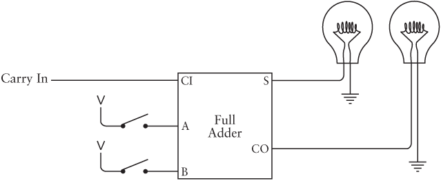
First connect the two rightmost switches and the rightmost lightbulb to a Full Adder:

When you begin adding two binary numbers, the first column of digits that you add is different. It's different because every subsequent column might include a carry bit from the previous column. The first column doesn't include a carry bit, which is why the carry input to the Full Adder is connected to ground. That means a 0 bit. The addition of the first pair of binary digits could, of course, result in a carry bit. That carry output is an input to the next column.
For the next two digits and the next lightbulb, you use a Full Adder wired this way:

The carry output from the first Full Adder is an input to this second Full Adder. Each subsequent column of digits is wired the same way. Each carry output from one column is a carry input to the next column.
Finally the eighth and last pair of switches are wired to the last Full Adder:
Here the final carry output goes to the ninth lightbulb.
We're done.
Here's another way to look at this assemblage of eight Full Adders, with each Carry Out serving as input to the next Carry In:

Here's the complete 8-Bit Adder drawn as one box. The inputs are labeled A0 through A7 and B0 through B7. The outputs are labeled S0 through S7 (for sum):
This is a common way to label the separate bits of a multibit number. The bits A0, B0, and S0 are the least-significant, or rightmost, bits. The bits A7, B7, and S7 are the most-significant, or leftmost, bits. For example, here's how these subscripted letters would apply to the binary number 0110-1001:
The subscripts start at 0 and get higher for more significant digits because they correspond to the exponents of powers of two:
If you multiply each power of two by the digit below it and add, you'll get the decimal equivalent of 0110-1001, which is 64 + 32 + 8 + 1, or 105.
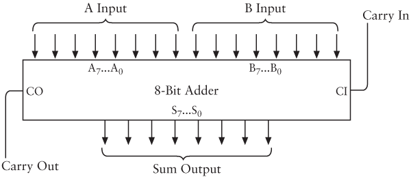
Another way an 8-Bit Adder might be drawn is like this:

The double-line arrows have an 8 inside to indicate that each represents a group of eight separate signals. They are labeled A7…A0, B7…B0, and S7…S0 also to indicate 8-bit numbers.
Once you build one 8-Bit Adder, you can build another. It then becomes easy to cascade them to add two 16-bit numbers:

The Carry Out of the adder on the right is connected to the Carry In of the adder on the left. The adder on the left has as input the most-significant eight digits of the two numbers to be added and creates as output the most-significant eight digits of the result.
And now you might ask, "Is this really the way that computers add numbers together?"
Basically, yes. But not exactly.
First, adders can be made faster than this one. If you look at how this circuit works, a carry output from the least-significant pair of numbers is required for the next pair to be added, and a carry output from the second pair is required for the third pair to be added, and so forth. The total speed of the adder is equal to the number of bits times the speed of the Full Adder component. This is called a ripple carry. Faster adders use additional circuitry called a look-ahead carry that speeds up this process.
Second (and most important), computers don't use relays any more! They did at one time, however. The first digital computers built beginning in the 1930s used relays and later vacuum tubes. Today's computers use transistors. When used in computers, transistors basically function the same way relays do, but (as we'll see) they're much faster and much smaller and much quieter and use much less power and are much cheaper. Building an 8-Bit Adder still requires 144 transistors (more if you replace the ripple carry with a look-ahead carry), but the circuit is microscopic.