
In some far-off distant time, when the twentieth century history of primitive computing is just a murky memory, someone is likely to suppose that devices known as logic gates were named after the famous co-founder of Microsoft Corporation. Not quite. As we'll soon see, logic gates bear a much greater resemblance to those ordinary gates through which pass water or people. Logic gates perform simple tasks in logic by blocking or letting through the flow of electrical current.
You'll recall how in the last chapter you went into a pet shop and announced, "I want a male cat, neutered, either white or tan; or a female cat, neutered, any color but white; or I'll take any cat you have as long as it's black." This is summarized by the following Boolean expression:
| (M x N x (W + T)) + (F x N x (1 – W)) + B |
and also by this circuit made up of switches and a lightbulb:

Such a circuit is sometimes called a network, except that nowadays that word is used much more often to refer to connected computers rather than an assemblage of mere switches.
Although this circuit contains nothing that wasn't invented in the nineteenth century, nobody in that century ever realized that Boolean expressions could be directly realized in electrical circuits. This equivalence wasn't discovered until the 1930s, most notably by Claude Elwood Shannon (born 1916), whose famous 1938 M.I.T. master's thesis was entitled "A Symbolic Analysis of Relay and Switching Circuits." (Ten years later, Shannon's article "The Mathematical Theory of Communication" was the first publication that used the word bit to mean binary digit.)
Prior to 1938, people knew that when you wired two switches in series, both switches had to be closed for current to flow, and when you wired two switches in parallel, one or the other had to be closed. But nobody had shown with Shannon's clarity and rigor that electrical engineers could use all the tools of Boolean algebra to design circuits with switches. In particular, if you can simplify a Boolean expression that describes a network, you can simplify the network accordingly.
For example, the expression that indicates the characteristics you want in a cat looks like this:
| (M x N x (W + T)) + (F x N x (1 – W)) + B |
Using the associative law, we can reorder the variables that are combined with the AND (x) signs and rewrite the expression this way:
| (N x M x (W + T)) + (N x F x (1 – W)) + B |
In an attempt to clarify what I'm going to do here, I'll define two new symbols named X and Y:
| X = M x (W + T) |
| Y = F x (1 – W) |
Now the expression for the cat you want can be written like this:
| (N x X) + (N x Y) + B |
After we're finished, we can put the X and Y expressions back in.
Notice that the N variable appears twice in the expression. Using the distributive law, the expression can be rewritten like this, with only one N:
| (N x (X + Y)) + B |
Now let's put the X and Y expressions back in:
| (N x ((M x (W + T)) + (F x (1 – W)))) + B |
Due to the plethora of parentheses, this expression hardly looks simplified. But there's one less variable in this expression, which means there's one less switch in the network. Here's the revised version:

Indeed, it's probably easier to see that this network is equivalent to the earlier one than to verify that the expressions are the same.
Actually, there are still three too many switches in this network. In theory, you need only four switches to define your perfect cat. Why four? Each switch is a bit. You should be able to get by with one switch for the sex (off for male, on for female), another switch that's on for neutered, off for unneutered, and two more switches for the color. There are four possible colors (white, black, tan, and "other"), and we know that four choices can be defined with 2 bits, so all you need are two color switches. For example, both switches can be off for white, one switch on for black, the other switch on for tan, and both switches on for other colors.
Let's make a control panel right now for choosing a cat. The control panel is simply four switches (much like the on/off switches you have on your walls for controlling your lights) and a lightbulb mounted in a panel:
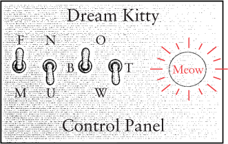
The switches are on (closed) when they're up, and off (open) when they're down. The two switches for the cat's color are labeled somewhat obscurely, I'm afraid, but that's a drawback of reducing this panel to the bare minimum: The left switch of the pair is labeled B; that means that the left switch on by itself (as shown) indicates the color black. The right switch of the pair is labeled T; that switch on by itself means the color tan. Both switches up means other colors; this choice is labeled O. Both switches down means the color white, indicated by W, the letter at the bottom.
In computer terminology, the switches are an input device. Input is information that controls how a circuit behaves. In this case, the input switches correspond to 4 bits of information that describe a cat. The output device is the lightbulb. This bulb lights up if the switches describe a satisfactory cat. The switches shown in the control panel on page 104 are set for a female unneutered black cat. This satisfies your criteria, so the lightbulb is lit.
Now all we have to do is design a circuit that makes this control panel work.
You'll recall that Claude Shannon's thesis was entitled "A Symbolic Analysis of Relay and Switching Circuits." The relays he was referring to were quite similar to the telegraph relays that we encountered in Chapter 6. By the time of Shannon's paper, however, relays were being used for other purposes and, in particular, in the vast network of the telephone system.
Like switches, relays can be connected in series and in parallel to perform simple tasks in logic. These combinations of relays are called logic gates. When I say that these logic gates perform simple tasks in logic, I mean as simple as possible. Relays have an advantage over switches in that relays can be switched on and off by other relays rather than by fingers. This means that logic gates can be combined to perform more complex tasks, such as simple functions in arithmetic. Indeed, the next chapter will demonstrate how to wire switches, lightbulbs, a battery, and telegraph relays to make an adding machine (albeit one that works solely with binary numbers).
As you recall, relays were crucial to the workings of the telegraph system. Over long distances, the wires connecting telegraph stations had a very high resistance. Some method was needed to receive a weak signal and send an identical strong signal. The relay did this by using an electromagnet to control a switch. In effect, the relay amplified a weak signal to create a strong signal.
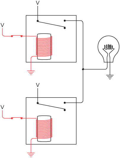
For our purposes, we're not interested in using the relay to amplify a weak signal. We're interested only in the idea of a relay being a switch that can be controlled by electricity rather than by fingers. We can wire a relay with a switch, a lightbulb, and a couple of batteries like this:

Notice that the switch at the left is open and the lightbulb is off. When you close the switch, the battery at the left causes current to flow through the many turns of wire around the iron bar. The iron bar becomes magnetic and pulls down a flexible metal contact that connects the circuit to turn on the lightbulb:
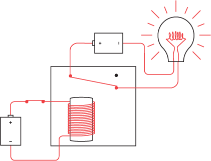
When the electromagnet pulls the metal contact, the relay is said to be triggered. When the switch is turned off, the iron bar stops being magnetic, and the metal contact returns to its normal position.
This seems like a rather indirect route to light the bulb, and indeed it is. If we were interested only in lighting the bulb, we could dispense with the relay entirely. But we're not interested in lighting bulbs. We have a much more ambitious goal.
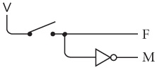
We're going to be using relays a lot in this chapter (and then hardly at all after the logic gates have been built), so I want to simplify the diagram. We can eliminate some of the wires by using a ground. In this case, the grounds simply represent a common connection; they don't need to be connected to the physical earth:
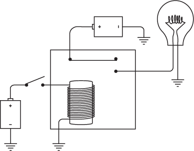
I know this doesn't look like a simplification, but we're not done yet. Notice that the negative terminals of both batteries are connected to ground. So anywhere we see something like this:
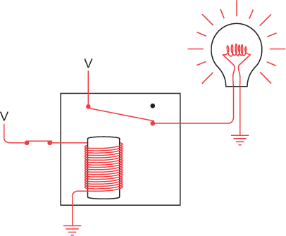
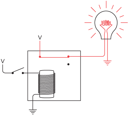
let's replace it with the capital letter V (which stands for voltage), as we did in Chapters Chapter 5 and Chapter 6. Now our relay looks like this:

When the switch is closed, a current flows between V and ground through the coils of the electromagnet. This causes the electromagnet to pull the flexible metal contact. That connects the circuit between V, the lightbulb, and ground. The bulb lights up:
These diagrams of the relay show two voltage sources and two grounds, but in all the diagrams in this chapter, all the V's can be connected to one another and all the grounds can be connected to one another. All the networks of relays and logic gates in this chapter and the next will require only one battery, although it might need to be a big battery. For example, the preceding diagram can be redrawn with only one battery like this:

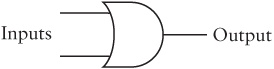
But for what we need to do with relays, this diagram isn't very clear. It's better to avoid the circular circuits and look at the relay—like the control panel earlier—in terms of inputs and outputs:
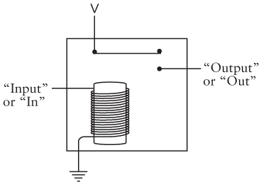
If a current is flowing through the input (for example, if a switch connects the input to V), the electromagnet is triggered and the output has a voltage.
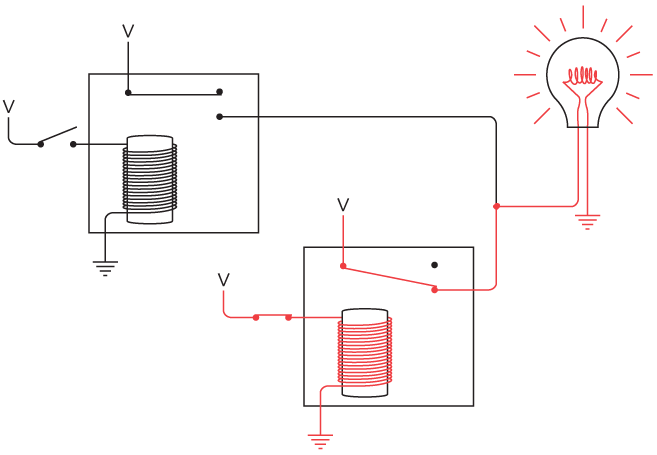
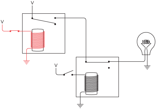
The input of a relay need not be a switch, and the output of a relay need not be a lightbulb. The output of one relay can be connected to the input of another relay, for example, like this:

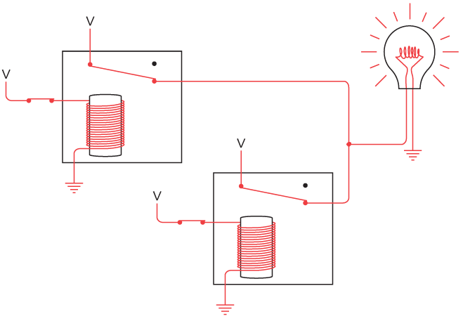
When you turn the switch on, the first relay is triggered, which then provides a voltage to the second relay. The second relay is triggered and the light goes on:

Connecting relays is the key to building logic gates.
Actually, the lightbulb can be connected to the relay in two ways. Notice the flexible metal piece that's pulled by the electromagnet. At rest, it's touching one contact; when the electromagnet pulls it, it hits another contact. We've been using that lower contact as the output of the relay, but we could just as well use the upper contact. When we use this contact, the output of the relay is reversed and the lightbulb is on when the input switch is open:

And when the input switch is closed, the bulb goes out:

Using the terminology of switches, this type of relay is called a double-throw relay. It has two outputs that are electrically opposite—when one has a voltage, the other doesn't.
By the way, if you're having a tough time visualizing what modern relays look like, you can see a few in conveniently transparent packaging at your local Radio Shack. Some, like the heavy-duty relays with Radio Shack part numbers 275-206 and 275-214, are about the size of ice cubes. The insides are encased in a clear plastic shell, so you can see the electromagnet and the metal contacts. The circuits I'll be describing in this chapter and the next could be built using Radio Shack part number 275-240 relays, which are smaller (about the size of a Chiclet) and cheaper ($2.99 apiece).
Just as two switches can be connected in series, two relays can be connected in series:
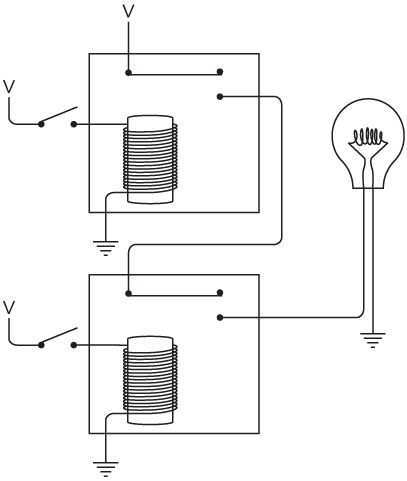
The output of the top relay supplies a voltage to the second relay. As you can see, when both switches are open, the lightbulb isn't lit. We can try closing the top switch:

Still the lightbulb doesn't light because the bottom switch is still open and that relay isn't triggered. We can try opening the top switch and closing the bottom switch:
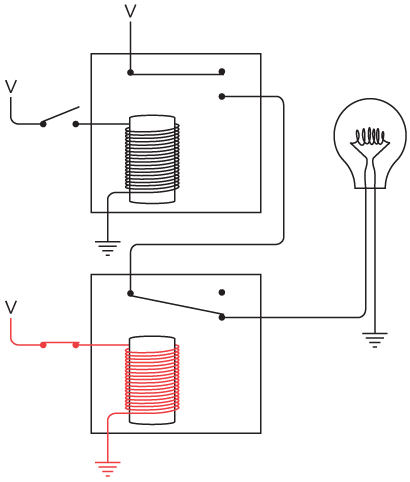
The lightbulb is still not lit. The current can't reach the lightbulb because the first relay isn't triggered. The only way to get the bulb to light up is to close both switches:
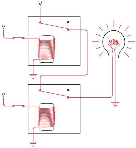
Now both relays are triggered, and current can flow between V, the lightbulb, and ground.
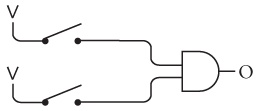
Like the two switches wired in series, these two relays are performing a little exercise in logic. The bulb lights up only if both relays are triggered. These two relays wired in series are known as an AND gate. To avoid excessive drawing, electrical engineers have a special symbol for an AND gate. That symbol looks like this:

This is the first of four basic logic gates. The AND gate has two inputs (at the left in this diagram) and one output (at the right). You'll often see the AND gate drawn as this one is with the inputs at the left and the output at the right. That's because people who are accustomed to reading from left to right also like to read electrical diagrams from left to right. But the AND gate can just as well be drawn with the inputs at the top, the right, or the bottom.
The original circuit with the two relays wired in series with two switches and a lightbulb looked like this:

Using the symbol for the AND gate, this same circuit looks like this:

Notice that this symbol for the AND gate not only takes the place of two relays wired in series, but it also implies that the top relay is connected to a voltage, and both relays are connected to ground. Again, the lightbulb lights up only if both the top switch and the bottom switch are closed. That's why it's called an AND gate.
The inputs of the AND gate don't necessarily have to be connected to switches, and the output doesn't necessarily have to be connected to a lightbulb. What we're really dealing with here are voltages at the inputs and a voltage at the output. For example, the output of one AND gate can be an input to a second AND gate, like this:

This bulb will light up only if all three switches are closed. Only if the top two switches are closed will the output of the first AND gate trigger the first relay in the second AND gate. The bottom switch triggers the second relay in the second AND gate.
If we think of the absence of a voltage as a 0, and the presence of a voltage as a 1, the output of the AND gate is dependent on inputs like this:

As with the two switches wired in series, the AND gate can also be described in this little table:
AND | 0 | 1 |
0 | 0 | 0 |
1 | 0 | 1 |
It's also possible to make AND gates with more than two inputs. For example, suppose you connect three relays in series:

The lightbulb lights up only if all three switches are closed. This configuration is expressed by this symbol:

It's called a 3-input AND gate.
The next logic gate involves two relays that are wired in parallel like this:

Notice that the outputs of the two relays are connected to each other. This connected output then provides power for the lightbulb. Either one of the two relays is enough to light the bulb. For example, if we close the top switch, the bulb lights up. The bulb is getting power from the left relay.

Similarly, if we leave the top switch open but close the bottom switch, the bulb lights up:
The bulb also lights if both switches are closed:
What we have here is a situation in which the bulb lights up if the top switch or the bottom switch is closed. The key word here is or, so this is called the OR gate. Electrical engineers use a symbol for the OR gate that looks like this:
It's somewhat similar to the symbol for the AND gate except that the input side is rounded, much like the O in OR. (That might help you to keep them straight.)
The output of the OR gate supplies a voltage if either of the two inputs has a voltage. Again, if we say that the absence of a voltage is 0 and the presence of a voltage is 1, the OR gate has four possible states:

In the same way that we summarized the output of the AND gate, we can summarize the output of the OR gate:
OR | 0 | 1 |
0 | 0 | 1 |
1 | 1 | 1 |
OR gates can also have more than two inputs. (The output of such a gate is 1 if any of the inputs are 1; the output is 0 only if all the outputs are 0.)
Earlier I explained how the relays that we're using are called double-throw relays because an output can be connected two different ways. Normally, the bulb isn't lit when the switch is open:

When the switch is closed, the bulb lights up.
Alternatively, you can use the other contact so that the bulb is lit when the switch is open:
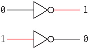
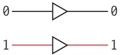
In this case, the lightbulb goes out when you close the switch. A single relay wired in this way is called an inverter. An inverter isn't a logic gate (logic gates always have two or more inputs), but it's often very useful nonetheless. It's represented by a special symbol that looks like this:
It's called an inverter because it inverts 0 (no voltage) to 1 (voltage) and vice versa:
With the inverter, the AND gate, and the OR gate, we can start wiring the control panel to automate a choice of the ideal kitty. Let's begin with the switches. The first switch is closed for female and open for male. Thus we can generate two signals that we'll call F and M, like this:
When F is 1, M will be 0 and vice versa. Similarly, the second switch is closed for a neutered cat and open for an unneutered cat:

The next two switches are more complicated. In various combinations, these switches must indicate four different colors. Here are the two switches, both wired to a voltage:

When both switches are open (as shown), they indicate the color white. Here's how to use two inverters and one AND gate to generate a signal I'll call W, which is a voltage (1) if you select a white cat and not a voltage (0) if not:

When the switches are open, the inputs to both inverters are 0. The outputs of the inverters (which are inputs to the AND gate) are thus both 1. That means the output of the AND gate is 1. If either of the switches is closed, the output of the AND gate will be a 0.
To indicate a black cat, we close the first switch. This can be realized using one inverter and an AND gate:

The output of the AND gate will be 1 only if the first switch is closed and the second switch is open.
Similarly, if the second switch is closed, we want a tan cat:

And if both switches are closed, we want a cat of an "other" color:
Now let's combine all four little circuits into one big circuit. (As usual, the black dots indicate connections between wires in the circuit; wires that cross without black dots are not connected.)

Yes, I know this set of connections now looks very complicated. But if you trace through very carefully—if you look at the two inputs to each AND gate to see where they're coming from and try to ignore where they're also going—you'll see that the circuit works. If both switches are off, the W output will be 1 and the rest will be 0. If the first switch is closed, the B output will be 1 and the rest will be 0, and so forth.
Some simple rules govern how you can connect gates and inverters: The output of one gate (or inverter) can be the input to one or more other gates (or inverters). But the outputs of two or more gates (or inverters) are never connected to one another.
This circuit of four AND gates and two inverters is called a 2-Line-to-4-Line Decoder. The input is two bits that in various combinations can represent four different values. The output is four signals, only one of which is 1 at any time, depending on the two input values. On similar principles, you can make a 3-Line-to-8-Line Decoder or a 4-Line-to-16-Line Decoder, and so forth.
The simplified version of the cat-selection expression was
| (N x ((M x (W + T)) + (F x (1 – W)))) + B |
For every + sign in this expression, there must be an OR gate in the circuit. For every x sign, there must be an AND gate.

The symbols down the left side of the circuit diagram are in the same order as they appear in the expression. These signals come from the switches wired with inverters and the 2-line-to-4-line decoder. Notice the use of the inverter for the (1 – W) part of the expression.
Now you might say, "That's a heck of a lot of relays," and yes, that's true. There are two relays in every AND gate and OR gate, and one relay for each inverter. I'd say the only realistic response is, "Get used to it." We'll be using a lot more relays in the chapters ahead. Just be thankful you don't actually have to buy them and wire them at home.
We'll look at two more logic gates in this chapter. Both use the output of the relay that normally has a voltage present when the relay is untriggered. (This is the output used in the inverter.) For example, in this configuration the output from one relay supplies power to a second relay. With both inputs off, the lightbulb is on:

If the top switch is closed, the bulb goes off:
The light goes off because power is no longer being supplied to the second relay. Similarly, if the bottom switch is closed, the light is also off:

And if both switches are closed, the lightbulb is off:

This behavior is precisely the opposite of what happens with the OR gate. It's called NOT OR or, more concisely, NOR. This is the symbol for the NOR gate:

It's the same as the symbol for the OR except with a little circle at the output. The circle means invert. The NOR is the same as

The output of the NOR gate is shown in the following table:
NOR | 0 | 1 |
0 | 1 | 0 |
1 | 0 | 0 |
This table shows results opposite those of the OR gate, which are 1 if either of the two inputs is 1 and 0 only if both inputs are 0.
And yet another way to wire two relays is shown here:

In this case, the two outputs are connected, which is similar to the OR configuration but using the other contacts. The lightbulb is on when both switches are open.
The lightbulb remains on when the top switch is closed:

Similarly, the lightbulb remains on when the bottom switch is closed:

Only when both switches are closed does the lightbulb go off:
This behavior is exactly opposite that of the AND gate. This is called NOT AND or, more concisely, NAND. The NAND gate is drawn just like the AND gate but with a circle at the output, meaning the output is the inverse of the AND gate:

The NAND gate has the following behavior:
NAND | 0 | 1 |
0 | 1 | 1 |
1 | 1 | 0 |
Notice that the output of the NAND gate is opposite the AND gate. The output of the AND gate is 1 only if both inputs are 1; otherwise, the output is 0.
At this point, we've looked at four different ways of wiring relays that have two inputs and one output. Each configuration behaves in a slightly different way. To avoid drawing and redrawing the relays, we've called them logic gates and decided to use the same symbols to represent them that are used by electrical engineers. The output of the particular logic gate depends on the input, which is summarized here:

So now we have four logic gates and the inverter. Completing this array of tools is just a regular old relay:

This is called a buffer, and this is the symbol for it:
It's the same symbol as the inverter but without the little circle. The buffer is remarkable for not doing much. The output of the buffer is the same as the input:
But you can use a buffer when an input signal is weak. You'll recall that this was the reason relays were used with the telegraph many years ago. Or a buffer can be used to slightly delay a signal. This works because the relay requires a little time—some fraction of a second—to be triggered.
From here on in the book, you'll see very few drawings of relays. Instead, the circuits that follow will be built from buffers, inverters, the four basic logic gates, and more sophisticated circuits (like the 2-Line-to-4-Line Decoder) built from these logic gates. All these other components are made from relays, of course, but we don't actually have to look at the relays.
Earlier, when building the 2-Line-to-4-Line Decoder, we saw a little circuit that looked like this:
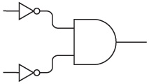
Two inputs are inverted and become inputs to an AND gate. Sometimes a configuration like this is drawn without the inverters:

Notice the little circles at the input to the AND gate. Those little circles mean that the signals are inverted at that point—a 0 (no voltage) becomes a 1 (voltage) and vice versa.
An AND gate with two inverted inputs does exactly the same thing as a NOR gate:
The output is 1 only if both inputs are 0.
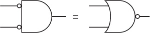
Similarly, an OR gate with the two inputs inverted is equivalent to a NAND gate:

The output is 0 only if both inputs are 1.
These two pairs of equivalent circuits represent an electrical implementation of De Morgan's Laws. Augustus De Morgan was another Victorianera mathematician, nine years older than Boole, whose book Formal Logic was published in 1847, the very same day (the story goes) as Boole's The Mathematical Analysis of Logic. Indeed, Boole had been inspired to investigate logic by a very public feud that was being waged between De Morgan and another British mathematician involving accusations of plagiarism. (De Morgan has been exonerated by history.) Very early on, De Morgan recognized the importance of Boole's insights. He unselfishly encouraged Boole and helped him along the way, and is today sadly almost forgotten except for his famous laws.
De Morgan's Laws are most simply expressed this way:

A and B are two Boolean operands. In the first expression, they're inverted and then combined with the Boolean AND operator. This is the same as combining the two operands with the Boolean OR operator and then inverting the result (which is the NOR). In the second expression, the two operands are inverted and then combined with the Boolean OR operator. This is the same as combining the operands with the Boolean AND operator and then inverting (which is the NAND).
De Morgan's Laws are an important tool for simplifying Boolean expressions and hence, for simplifying circuits. Historically, this was what Claude Shannon's paper really meant for electrical engineers. But obsessively simplifying circuits won't be a major concern in this book. It's preferable to get things working rather than to get things working as simply as possible. And what we're going to get working next is nothing less than an adding machine.