
You're twelve years old. One horrible day your best friend's family moves to another town. You speak to your friend on the telephone now and then, but telephone conversations just aren't the same as those late-night sessions with the flashlights blinking out Morse code. Your second-best friend, who lives in the house next door to yours, eventually becomes your new best friend. It's time to teach your new best friend some Morse code and get the late-night flashlights blinking again.
The problem is, your new best friend's bedroom window doesn't face your bedroom window. The houses are side by side, but the bedroom windows face the same direction. Unless you figure out a way to rig up a few mirrors outside, the flashlights are now inadequate for after-dark communication.
Or are they?
Maybe you have learned something about electricity by this time, so you decide to make your own flashlights out of batteries, lightbulbs, switches, and wires. In the first experiment, you wire up the batteries and switch in your bedroom. Two wires go out your window, across a fence, and into your friend's bedroom, where they're connected to a lightbulb:

Although I'm showing only one battery, you might actually be using two. In this and future diagrams, this will be an off (or open) switch:
and this will be the switch when it's on (or closed):
The flashlight in this chapter works the same way as the one illustrated in the previous chapter, although the wires connecting the components for this chapter's flashlight are a bit longer. When you close the switch at your end, the light goes on at your friend's end:

Now you can send messages using Morse code.
Once you have one flashlight working, you can wire another long-distance flashlight so that your friend can send messages to you:

Congratulations! You have just rigged up a bidirectional telegraph system. You'll notice that these are two identical circuits that are entirely independent of and unconnected to each other. In theory, you can be sending a message to your friend while your friend is sending a message to you (although it might be hard for your brain to read and send messages at the same time).
You also might be clever enough to discover that you can reduce your wire requirements by 25 percent by wiring the configuration this way:

Notice that the negative terminals of the two batteries are now connected. The two circular circuits (battery to switch to bulb to battery) still operate independently, even though they're now joined like Siamese twins.
This connection is called a common. In this circuit the common extends from the point where the leftmost lightbulb and battery are connected to the point where the rightmost lightbulb and battery are connected. These connections are indicated by dots.
Let's take a closer look to assure ourselves that nothing funny is going on. First, when you depress the switch on your side, the bulb in your friend's house lights up. The red wires show the flow of electricity in the circuit:
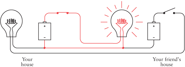
No electricity flows in the other part of the circuit because there's no place for the electrons to go to complete a circuit.
When you're not sending but your friend is sending, the switch in your friend's house controls the lightbulb in your house. Once again, the red wires show how electricity flows in the circuit:

When you and your friend both try to send at the same time, sometimes both switches are open, sometimes one switch is closed but the other is open, and sometimes both switches are depressed. In that case, the flow of electricity in the circuit looks like this:

No current flows through the common part of the circuit.
By using a common to join two separate circuits into one circuit, we've reduced the electrical connection between the two houses from four wires to three wires and reduced our wire expenses by 25 percent.
If we had to string the wires for a very long distance, we might be tempted to reduce our expenses even more by eliminating another wire. Unfortunately, this isn't feasible with 1.5-volt D cells and small lightbulbs. But if we were dealing with 100-volt batteries and much larger lightbulbs, it could certainly be done.
Here's the trick: Once you have established a common part of the circuit, you don't have to use wire for it. You can replace the wire with something else. And what you can replace it with is a giant sphere approximately 7900 miles in diameter made up of metal, rock, water, and organic material, most of which is dead. The giant sphere is known to us as Earth.
When I described good conductors in the last chapter, I mentioned silver, copper, and gold, but not gravel and mulch. In truth, the earth isn't such a hot conductor, although some kinds of earth (damp soil, for example) are better than others (such as dry sand). But one thing we learned about conductors is this: The larger the better. A very thick wire conducts much better than a very thin wire. That's where the earth excels. It's really, really, really big.
To use the earth as a conductor, you can't merely stick a little wire into the ground next to the tomato plants. You have to use something that maintains a substantial contact with the earth, and by that I mean a conductor with a large surface area. One good solution is a copper pole at least 8 feet long and ½ inch in diameter. That provides 150 square inches of contact with the earth. You can bury the pole into the ground with a sledgehammer and then connect a wire to it. Or, if the cold-water pipes in your home are made of copper and originate in the ground outside the house, you can connect a wire to the pipe.
An electrical contact with the earth is called an earth in Great Britain and a ground in America. A bit of confusion surrounds the word ground because it's also often used to refer to a part of a circuit we've been calling the common. In this chapter, and until I indicate otherwise, a ground is a physical connection with the earth.
When people draw electrical circuits, they use this symbol to represent a ground:

Electricians use this symbol because they don't like to take the time to draw an 8-foot copper pole buried in the ground.
Let's see how this works. We began this chapter by looking at a one-way configuration like this:
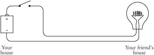
If you were using high-voltage batteries and lightbulbs, you would need only one wire between your house and your friend's house because you could use the earth as one of the connectors:

When you turn the switch on, electricity flows like this:

The electrons come out of the earth at your friend's house, go through the lightbulb and wire, the switch at your house, and then go into the positive terminal of the battery. Electrons from the negative terminal of the battery go into the earth.
You might also want to visualize electrons leaping from the 8-foot copper pole buried in the backyard of your house into the earth, then scurrying through the earth to get to the 8-foot copper pole buried in the backyard of your friend's house.
But if you consider that the earth is performing this same function for many thousands of electrical circuits around the world, you might ask: How do the electrons know where to go? Well, obviously they don't. A different image of the earth seems much more appropriate.
Yes, the earth is a massive conductor of electricity, but it can also be viewed as both a source of and a repository for electrons. The earth is to electrons as an ocean is to drops of water. The earth is a virtually limitless source of electrons and also a giant sink for electrons.
The earth, however, does have some resistance. That's why we can't use the earth ground to reduce our wiring needs if we're playing around with 1.5-volt D cells and flashlight bulbs. The earth simply has too much resistance for low-voltage batteries.
You'll notice that the previous two diagrams include a battery with the negative terminal connected to the ground:

I'm not going to draw this battery connected to the ground anymore. Instead, I'm going to use the capital letter V, which stands for voltage. The one-way lightbulb telegraph now looks like this:
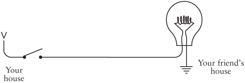
The V stands for voltage, but it could also stand for vacuum. Think of the V as an electron vacuum and think of the ground as an ocean of electrons. The electron vacuum pulls the electrons from the earth through the circuit, doing work along the way (such as lighting a lightbulb).
The ground is sometimes also known as the point of zero potential. This means that no voltage is present. A voltage—as I explained earlier—is a potential for doing work, much as a brick suspended in the air is a potential source of energy. Zero potential is like a brick sitting on the ground—there's no place left for it to fall.
In Chapter 4, one of the first things we noticed was that circuits were circles. Our new circuit doesn't look like a circle at all. It still is one, however. You could replace the V with a battery with the negative terminal connected to ground, and then you could draw a wire connecting all the places you see a ground symbol. You'd end up with the same diagram that we started with in this chapter.
So with the help of a couple of copper poles (or cold-water pipes), we can construct a two-way Morse code system with just two wires crossing the fence between your house and your friend's:
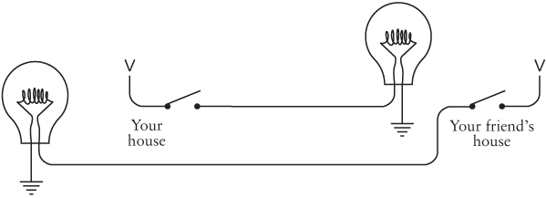
This circuit is functionally the same as the configuration shown previously, in which three wires crossed the fence between the houses.
In this chapter, we've taken an important step in the evolution of communications. Previously we had been able to communicate with Morse code but only in a straight line of sight and only as far as the beam from a flash-light would travel.
By using wires, not only have we constructed a system to communicate around corners beyond the line of sight, but we've freed ourselves of the limitation of distance. We can communicate over hundreds and thousands of miles just by stringing longer and longer wires.
Well, not exactly. Although copper is a very good conductor of electricity, it's not perfect. The longer the wires, the more resistance they have. The more resistance, the less current that flows. The less current, the dimmer the lightbulbs.
So how long exactly can we make the wires? That depends. Let's suppose you're using the original four-wire, bidirectional hookup without grounds and commons, and you're using flashlight batteries and lightbulbs. To keep your costs down, you may have initially purchased some 20-gauge speaker wire from Radio Shack at $9.99 per 100 feet. Speaker wire is normally used to connect your speakers to your stereo system. It has two conductors, so it's also a good choice for our telegraph system. If your bedroom and your friend's bedroom are less than 50 feet apart, this one roll of wire is all you need.
The thickness of wire is measured in American Wire Gauge, or AWG. The smaller the AWG number, the thicker the wire and also the less resistance it has. The 20-gauge speaker wire you bought has a diameter of about 0.032 inches and a resistance of about 10 ohms per 1000 feet, or 1 ohm for the 100-foot round-trip distance between the bedrooms.
That's not bad at all, but what if we strung the wire out for a mile? The total resistance of the wire would be more than 100 ohms. Recall from the last chapter that our lightbulb was only 4 ohms. From Ohm's Law, we can easily calculate that the current through the circuit will no longer be 0.75 amp (3 volts divided by 4 ohms) as before, but will now be less than 0.03 amp (3 volts divided by more than 100 ohms). Almost certainly, that won't be enough current to light the bulb.
Using thicker wire is a good solution, but that can be expensive. Ten-gauge wire (which Radio Shack sells as Automotive Hookup Wire at $11.99 for 35 feet, and you'd need twice as much because it has only one conductor rather than two) is about 0.1 inch thick but has a resistance of only 1 ohm per 1000 feet, or 5 ohms per mile.
Another solution is to increase the voltage and use lightbulbs with a much higher resistance. For example, a 100-watt lightbulb that lights a room in your house is designed to be used with 120 volts and has a resistance of about 144 ohms. The resistance of the wires will then affect the overall circuitry much less.
These are problems faced 150 years ago by the people who strung up the first telegraph systems across America and Europe. Regardless of the thickness of the wires and the high levels of voltage, telegraph wires simply couldn't be continued indefinitely. At most, the limit for a working system according to this scheme was a couple hundred miles. That's nowhere close to spanning the thousands of miles between New York and California.
The solution to this problem—not for flashlights but for the clicking and clacking telegraphs of yesteryear—turns out to be a simple and humble device, but one from which entire computers can be built.