
CCHP Solar Heat Collectors
Abstract
Keywords
Solar collector
azimuth angle
tilting angle
collector size
CCHP cycle
optimization
7.1. Introduction
Integrating renewable energy resources such as solar energy with the high efficiency energy conversion equipment such as CCHP systems amplify the benefits of these technologies. Solar energy systems can be used as photovoltaic cells to provide solar electricity, as heating collectors for heating, or as photovoltaic/thermal (PVT) systems for combined production of heat and electricity [9]. Solar collectors appear in different shapes and types such as plate, concentric, parabolic, evacuated tube, etc. [10, 11]. Solar thermal energy and recovered heat from the CCHP system can be combined to provide as much as possible of the aggregated thermal demand. They also can be used as the running energy of ORC-CCHP cycles. Some of the CCHP systems that have used solar technologies were presented in Figures 1.5, 1.14, 1.21, 1.22, and 2.32.
Solar system selection depends on the heat demand, temperature required, and application. The most common type for commercial, residential, and low-temperature industrial applications is the plate collector. This type of collector can provide air or hot water at a temperature of up to 93 °C but its efficiency decreases rapidly below 50% at temperatures higher than 70 °C. These collectors usually are installed in a fixed position. Wolf GmbH is a main producer of this type of collector [12]. Concentrating collectors are also available for high-temperature industrial applications and provide hot water with temperatures higher than 115 °C. These collectors need a sun tracer to receive as much solar heat as possible. [11]. Chromasun, Inc. has produced a micro concentrator (MCT) that is able to produce hot water with a temperature of up to 200 °C while maintaining an efficiency higher than 50% [13]. Figure 7.1 compares the MCT working temperature range and efficiency with different types of collectors. The collector efficiency is defined as the ratio of useful heat gained by the collector per unit of aperture area (W/m2) to the total irradiation of the collector (W/m2).

In order to design an optimum hybrid fossil fuel/solar-driven CCHP system two important steps must be taken.
First, the direction and orientation of the solar collector must be optimized to receive the maximum solar heat at that position. Theoretically, we can find an optimum orientation for the solar collector at every time and location to receive the maximum solar heat at that time and location. However, in practice usually a year is divided into some limited number of periods and an optimum orientation for each period can be calculated. For example, we can design one optimum direction to receive the maximum yearly solar energy, or four optimum orientations for the four seasons. This means that the collector orientation must be adjusted for every season according to its corresponding optimum orientation. When heat gain and optimum direction of the collector are determined, the size of the collector should be optimized in the second step. Collector size should be chosen so that the extra cost due to the solar system is recovered by decreasing the engine and auxiliary boiler size as well as by decreasing fuel consumption and environmental pollution.
Since the MRM and EMS sizing methods are independent from component type and size, these methods cannot be used for designing a hybrid fossil fuel/solar CCHP system. The methods that best suit this problem are the fitness function (ff) and multicriteria sizing function (MCSF). These methods are influenced by consumer demands and component type and size as well. In the following the calculation of the solar heat gain by a plate collector is presented and then it is shown how the optimum direction can be found. In addition, the size of the solar collector is calculated and we discuss how it can be determined according to the engine size and building demand.
7.2. Solar Heat Gain Calculation [10, 11, 14, and 15]
Among different types of solar collectors the most common type, the plate collector, is considered for coupling with a CCHP system. In addition, two options, single glazing and double glazing, are considered. The total heat gain of a plate collector with area Aco is defined as follows:
In the above equation qu is the collector heat index in watts per square meter of the collector area. In this section was want to find the magnitude of the collector heat index in the optimum direction.
The collector heat index is the maximum average heat that the collector absorbs during a period of time in the optimum orientation. The axis on which the Earth spins is tilted 23.45°. In order to find the collector heat index, the declination angle δ must be calculated for each day of year. This angle is shown in Figure 7.2. As can be seen it is the angle between the sun rays and equator, and is calculated as follows:
 (7-2)
(7-2)where N is the day number starting with N = 1 for January 1st and ending with N = 365 for December 31st, and annual changes of δ are negligible. The sun orientation is determined by solar azimuth angle azs in the horizontal plane (angle HOS), and the solar altitude σ (angle HOQ in Figure 7.3).


The solar angular hour AH is also calculated as follows:
 (7-3)
(7-3)
Therefore, σ and azs are calculated as follows:
 (7-6)
(7-6)The angle between the sun array attacking earth at point O (OQ), and the perpendicular axis to the collector (OP’) is called the incident angle θ and is calculated as follows:
where Σ is the tilting angle of the collector and γ is the collector-sun azimuth angle. When the collector is facing southeast γ is
 (7-8)
(7-8)where ψ is the collector azimuth angle; if the collector faces southwest γ is
 (7-9)
(7-9)For calculation of the total solar heat gained during each day of a year, the day length (DL) sunrise time, and sunset time are required and are calculated as follows:
 (7-10)
 (7-11)
The direct solar radiation on the Earth’s surface with a cloudless and clean sky is calculated by the following equation:
where A and B are apparent extraterrestrial irradiation and atmospheric extinction coefficient, respectively. They are functions of the date and take into account the seasonal variation of the Earth/Sun distance and the air’s water vapor content. The magnitudes of A and B are curve fitted according to the data presented in Ref. [10] as follows:
 (7-13)
 (7-14)
The total solar irradiation Itθ of a collector for any direction and tilting angle Σ with an incidence angle of θ is measured as follows:
where ![]() is the direct irradiation component,
is the direct irradiation component, ![]() is the diffusion coming from the sky, and
is the diffusion coming from the sky, and ![]() is the reflected short wave irradiation from the foreground that possibly reaches the collector. To estimate the diffuse component, dimensionless parameter C is defined; it depends on the dust and moisture content of the atmosphere and changes through the year. It is defined by the following equation:
is the reflected short wave irradiation from the foreground that possibly reaches the collector. To estimate the diffuse component, dimensionless parameter C is defined; it depends on the dust and moisture content of the atmosphere and changes through the year. It is defined by the following equation:
 (7-16)
where ![]() is the diffuse component on a horizontal surface on a cloudless day. The following equation is used to estimate the diffuse irradiation on a collector with a tilting angle of Σ:
is the diffuse component on a horizontal surface on a cloudless day. The following equation is used to estimate the diffuse irradiation on a collector with a tilting angle of Σ:
 (7-17)
where C is curve fitted using the data presented in Ref. [10], as follows:
 (7-18)
The reflected component can be calculated as follows:
 (7-19)
where ![]() is the reflectance coefficient and
is the reflectance coefficient and ![]() is the total radiation on a horizontal surface. Bituminous surfaces reflect less than 10% of the total solar irradiation [10]. For simplicity in this investigation it is assumed
is the total radiation on a horizontal surface. Bituminous surfaces reflect less than 10% of the total solar irradiation [10]. For simplicity in this investigation it is assumed ![]() . If the place where the collector is installed is something other than bituminous, the reflectance should be modified. Finally the heat gained by the collector is calculated as follows:
. If the place where the collector is installed is something other than bituminous, the reflectance should be modified. Finally the heat gained by the collector is calculated as follows:
To calculate the solar heat at every hour, the ambient temperature should be given for every hour (HR) of each day (N). The data from Ref. [10] are curve fitted to calculate τ, α, and UL as follows:
 (7-21)
 (7-22)
 (7-25)
In order to find the optimum collector direction to receive the maximum average annual solar heat the following procedure should be followed.
1. After calculation of qu at every hour of daytime during a year, the yearly average value of qu for every pair of (Σ, ψ) should be calculated ( ![]() ).
).
2. The angle pair (Σ, ψ) in which ![]() is maximum should be determined as (Σopt, ψopt).
is maximum should be determined as (Σopt, ψopt).
3. The maximum of ![]() is the collector heat index and is shown by
is the collector heat index and is shown by ![]() , hence
, hence
 (7-26)
7.3. Collector Size
After calculation of the collector heat index, the size of the collector should be determined. Since the solar energy is used in parallel with the heat recovery from the prime mover, the summation of these two heat sources is responsible for providing the heating, cooling, DHW, or ATD. For this purpose four strategies can be considered as follows:
ATD strategy: The collector is designed to provide ATDmax, therefore
H strategy: The collector is designed to provide the maximum heating load demand (Hdem, max), therefore
C strategy: The collector is designed to fulfill the maximum cooling load (Cdem, max), therefore
 (7-29)
D strategy: The collector is designed to provide Ddem, max, therefore
When DHW is integrated into the CCHP system (intg-DHW) the first three strategies are applicable; if DHW is separated from the CCHP system (sprt-DHW) the last three strategies are applicable. Choosing the best strategy for collector sizing depends of the thermodynamic, environmental, and economic evaluations. In this study DHW is integrated into the CCHP system.
With regard to collector sizing strategies it should be noted that the maximum cooling, heating, and ATD remains constant, but the recoverable heat from the engine is changeable due to possible changing of the prime mover size in the optimization process. Therefore the collector size changes with the size of the engine and the optimum collector size for the CCHP will be chosen according to the evaluation criteria of the CCHP cycle.
7.4. Case Study
In this chapter we will use solar thermal energy in the CCHP system that was designed in the previous chapter. The cycle is depicted in Figure 7.4.

In the natural gas/solar-driven CCHP an internal combustion engine is used to produce electricity, as chosen in Chapter 4. As can be seen a branch of water that is supposed to be heated for production of cooling, heating, or DHW is heated through the solar system and the rest of the water flows through the heat recovery exchangers to capture the heat from the lube oil, water jacketing, and exhaust gases. Then they mix together and enter the auxiliary boiler; if needed the boiler starts heating water to reach an appropriate energy level according to the building demands, otherwise a temperature control valve (TCV) bypasses the water to down stream of the boiler. The output of the auxiliary boiler can enter a fan coil unit (FCU) for heating purposes or the absorption chiller to produce chilled water. The chilled water is sent to the FCU for cooling purposes. DHW is extracted from the pipe just after the heat recovery exchangers, and the make-up water is also supplied to the main water line just before the auxiliary boiler to avoid overheating in the boiler. Since the solar system provides heat during the daytime we expect decreased fuel consumption from the auxiliary boiler and decreased fuel cost accordingly. In addition decreasing the fuel consumption decreases environmental pollutions as well. It should be noted that different designers may consider different configurations for the solar collector and the basic CCHP system depending on the temperature that the solar collector can produce.
In the first step the optimum direction of the collector is determined for the five climates. In addition the results are compared for single- and double-glazed collectors.
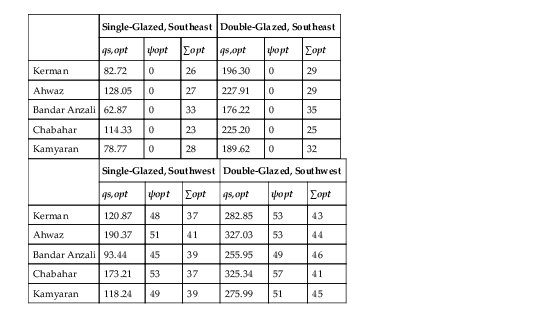
Figure 7.5 presents the annual average solar heat gain in the climate of Kamyaran when the collector faces southwest. The collector is double-glazed. As can be seen an optimum value happens at a particular angle pair of (ψ, Σ). The graphs of other climates and directions follow the same pattern and to avoid repetition only Figure 7.5 is presented, but the final results are tabulated in Table 7.1. As this table shows, the optimum direction for the five climates is southwest with different angles of (ψ, Σ). In addition the double-glazed collector receives more heat than the single-glazed type. Among the five climates, the climate of Ahwaz benefits most from the solar energy and receives 327.03 W/m2. Bandar Anzali receives the least solar energy at 255.95 W/m2.

Table 7.1
Optimum Direction, Type, and Collector Heat Index in Five Climates
| Single-Glazed, Southeast | Double-Glazed, Southeast | |||||
| qs,opt | ψopt | ∑opt | qs,opt | ψopt | ∑opt | |
| Kerman | 82.72 | 0 | 26 | 196.30 | 0 | 29 |
| Ahwaz | 128.05 | 0 | 27 | 227.91 | 0 | 29 |
| Bandar Anzali | 62.87 | 0 | 33 | 176.22 | 0 | 35 |
| Chabahar | 114.33 | 0 | 23 | 225.20 | 0 | 25 |
| Kamyaran | 78.77 | 0 | 28 | 189.62 | 0 | 32 |
| Single-Glazed, Southwest | Double-Glazed, Southwest | |||||
| qs,opt | ψopt | ∑opt | qs,opt | ψopt | ∑opt | |
| Kerman | 120.87 | 48 | 37 | 282.85 | 53 | 43 |
| Ahwaz | 190.37 | 51 | 41 | 327.03 | 53 | 44 |
| Bandar Anzali | 93.44 | 45 | 39 | 255.95 | 49 | 46 |
| Chabahar | 173.21 | 53 | 37 | 325.34 | 57 | 41 |
| Kamyaran | 118.24 | 49 | 39 | 275.99 | 51 | 45 |
In the second step, the collector size must be determined. As discussed in Eqs. (7-27) to (7-30) the collector size depends on the engine size and maximum of Hdem, Cdem, DHW, and ATD. This dependency is demonstrated in Figure 7.6 for the climate of Kamyaran. The other climates follow a similar pattern, therefore to avoid repetition only the results for Kamyaran are presented. As can be seen the collector area decreases as the engine size increases and finally in a particular engine size the collector area becomes zero. This means that since it is assumed that the engine is operating at full load, the recoverable heat fulfills the cooling, heating, and DHW demands of the building. In addition the auxiliary boiler size is depicted in Figure 7.7 and it shows that the boiler size in different strategies is approximately the same and similar to that calculated for the basic CCHP system. The reason is that the solar system cannot receive thermal energy at night, therefore the system should be designed to provide all the energy demands at all times. It is worth mentioning that using a thermal storage system decreases the boiler size because it can store surplus heat during daytime and reuse it at night.


To determine the engine size and collector area, the fitness function is utilized, and the results for the five climates are presented in Table 7.2.
Table 7.2
Engine Size and Collector Area for Different Strategies in Five Climates
| Climate | ATD | H | C | |
| Ahwaz | Enom(kW) | 33 | 288 | 33 |
| Aco(m2) | 1451 | 0 | 1459 | |
| Kerman | Enom(kW) | 118 | 58 | 100 |
| Aco(m2) | 0.43 | 0 | 0 | |
| Bandar Anzali | Enom(kW) | 29 | 117 | 155 |
| Aco(m2) | 788 | 0 | 0 | |
| Chabahar | Enom(kW) | 255 | 159 | 236 |
| Aco(m2) | 0 | 0 | 0 | |
| Kamyaran | Enom(kW) | 160 | 78 | 141 |
| Aco(m2) | 0 | 0 | 0 |

According to Table 7.2, the ff recommends not using a solar collector in most cases. After determining the economic criteria, it was revealed that the solar collector price is still too high and cannot compete with other equipment such as the heat recovery of an engine or auxiliary boiler. In some cases such as Ahwaz or Bandar Anzali, the recommended size of the collector has increased dramatically on one side and the engine size has decreased significantly on the other side. Using 1451 m2 of solar collector (for Ahwaz) on the roof of the building that has been analyzed is impossible. In order to make solar collectors more popular it is recommended that they be supported by governments, banks, and energy and environmental organizations through subsidies, proper loans, carbon credits, etc.
7.5. Problems
1. According to the formulations presented for the plate collector, determine the optimum direction for a solar collector in the city where you live.
2. If you have written code for the problem 6 presented in the previous chapter, couple it with the solar code written for Problem 1.
3. The hybrid CCHP in this chapter is designed based on ff; use the MCSF to redesign the hybrid CCHP system and compare the results with the ff.
4. If you are required to use a concentric parabolic collector (CPC), what would be the difference in the formulation in comparison to the plate collector? You can use [10, 14] to find the difference.
5. What would be the advantages of using PVT technology instead of a plate collector with the CCHP designed in this chapter? Does it reduce the engine size? What would be your prediction about the auxiliary boiler size?
6. Discuss the technological, economic, and environmental characteristics of using a thermal storage system instead of the auxiliary boiler when the need arises.
7. Assume we have a CCHP system integrated with PVT technology and a combination of electrical and absorption chillers. The absorption chiller is supposed to be used for the cooling base load and the electrical chiller is operated at cooling peak loads. Draw the schematic of this CCHP system and modify the formulations for this novel CCHP system.