4
Trihedron
4.1. Writing convention
The change of reference matrix making it possible to go from reference A to reference B in the axes of reference A is noted Matrix A/B in the rest of the book.
For example, the position of the aircraft in the aircraft frame E with respect to the local geographic frame can be written in the axes of the aircraft frame using the change of frame matrix Matrix E/LGT given in section 4.5.1.
4.2. Definitions of trihedrons
4.2.1. Definition of a trihedron or frame of reference
The association of the space frame ![]() and the time frame constitutes a frame of reference (R).
and the time frame constitutes a frame of reference (R).
In the remainder of the book, we will note, for simplicity, the frame of reference (R) as follows:
4.2.2. Galilean trihedron
In physics, a Galilean or inertial frame of reference is a frame in which an isolated object (on which no force is exerted or on which the resultant of the forces is zero) is in uniform rectilinear translational movement (immobility being a particular case of uniform rectilinear movement): the speed of the body is constant (over time) in direction and in norm.
This means that the principle of inertia, which is stated in Newton’s first law – “every body perseveres in the state of rest or of uniform straight-line motion in which it finds itself, unless some force acts upon it and compels it to change its state” – is true.
A Galilean referential is thus called as such as a tribute to Galileo and more particularly to Galilean relativity.
The search for an inertial frame of reference is a delicate subject; the concrete determination of such a frame of reference is always approximate.
In a non-inertial frame of reference, which is animated by an accelerated movement relative to a Galilean frame of reference, inertial forces must intervene.
4.2.3. Absolute trihedron
We assume that there are at least three stars, E1, E2 and E3, considered as points, which, together with the center of mass S of the solar system, form an undeformable tetrahedron.
Let ![]() be an orthonormal coordinate system rigidly linked to this tetrahedron. By providing this frame of reference with a time base, we constitute the Kepler frame of reference (K), which we assume to be Galilean.
be an orthonormal coordinate system rigidly linked to this tetrahedron. By providing this frame of reference with a time base, we constitute the Kepler frame of reference (K), which we assume to be Galilean.
This trihedron is also called the Copernicus or Kepler trihedron.
4.2.4. Local geographic trihedron
The Earth being assimilated to a sphere with center G, the frame of reference (LGT) is constituted using the frame of reference (OXT,OYT,OZT) defined as follows:
- – O is a point on the surface of the Earth;
- – OXT is tangent to the meridian and directed towards the north;
- – OYT is tangent to the parallel of O and directed towards the east;
- – OZT is directed towards the center of the Earth.
4.2.5. Terrestrial trihedron
The Earth being assimilated to a sphere of center G, the terrestrial reference frame (TER) is defined as follows:
- – G is the center of the Earth;
- – GxT is tangent to the meridian and directed towards the north;
- – GyT is tangent to the parallel of G and directed towards the east;
- – GzT completes this direct trihedron (directed towards the center of the Earth).
4.2.6. Aircraft trihedron
The aircraft trihedron (drone, helicopter, plane, etc.), or Lilienthal axis system (G,Xe,Ye,Ze), is defined as follows:
- – the trihedron has an origin G, which is the center of gravity of the aircraft;
- – GXe is the longitudinal axis, which is carried by the axis of the aircraft towards the nose of the aircraft;
- – GYe is the axis perpendicular to the plane of symmetry, oriented to the right (pilot direction);
- – GZe ┴ GXe is located in the plane of symmetry of the aircraft and oriented ˃ 0 towards the belly of the aircraft (towards the center of the Earth); it completes the direct trihedron.
4.2.7. Aircraft aerodynamic speed trihedron (G, Xvae, Yvae, Zvae)
The aerodynamic speed trihedron of the aircraft (G, Xvae, Yvae, Zvae) is defined as follows:
- – the trihedron has an origin G, which is the center of gravity of the aircraft;
- – GXvae is carried by the aerodynamic speed;
- – GZvae ┴ GXvae is located in the plane of symmetry of the aircraft and oriented ˃ 0 towards the belly of the aircraft (towards the center of the Earth);
- – GYvae completes the direct trihedron.
4.2.8. Balance trihedron
The coefficients on tracks y (GYb)and z (GZb) are restored in an aircraft trihedron demodulated of the aerodynamic roll. The balance trihedron is defined as follows (G,Xb,Yb,Zb):
- – the trihedron has an origin G, which is the center of measurement of the balance;
- – GXb is carried by the X axis of the aircraft;
- – GZb is located in the plane of symmetry of the aircraft and oriented ˃ 0 towards the belly of the aircraft (towards the center of the Earth);
- – GYb completes the direct trihedron.
4.3. Change of reference
The trihedrons presented in Figures 4.1–4.3 make it possible to visualize the rotations applied to the machine, as well as the projections on the various planes of symmetry of the aircraft.
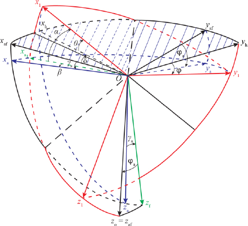
Figure 4.1. Reference trihedra of the machine. Passage from the aircraft reference to the local geographical reference. β ˂ 0; γa ˂ 0. For a color version of this figure, see www.iste.co.uk/louis/flight.zip
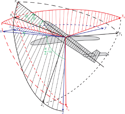
Figure 4.2. Reference trihedrons linked to the plane and the trajectory. In black: trihedron (G, x1, y1, z1) linked to the aircraft; in red: trihedron (G, xh, yh, z0) linked to the vertical; in blue: trihedron (G, x, y, z) linked to the speed. The angle i shown is positive, and the angle j shown is negative. For a color version of this figure, see www.iste.co.uk/louis/flight.zip
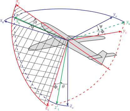
Figure 4.3. Reference trihedra defining the angular position of the aircraft in space Φ1 = Φ. In blue: the reference trihedron (G, x0, y0, z0), Gz0 depends on the gravity; in red: the plane trihedron (G, x1, y1, z1). The hatched area is in the plane of symmetry of the aircraft. For a color version of this figure, see www.iste.co.uk/louis/flight.zip
4.4. Relation between trihedra
4.4.1. Aircraft trihedron (G, X1, Y1, Z1) with respect to the reference trihedron (G, X0, Y0, Z0)
This position is defined by the coordinates of the center of gravity G and the relative orientation of the axes. From the coordinates of G, only the altitude Z is kept. The relative position is defined by Figure 4.3. We used, to define the angles, the trihedron (G,Xh,Yh,Z0), where GXh is the projection of GX1on the horizontal plane passing through G:
- – Ψ: the angle defining the azimuth (or the heading if OX0 is directed towards the north);
- – θ: the longitudinal attitude angle (also called the attitude);
- – ϕ: the roll angle.
We still use the angles θ1 and ϕ2. (G,X,Z) is the intersection of the plane of symmetry(G,X1,Z1) with the horizontal plane of G:
- – θ1: the pitch angle;
- – ϕ2: the angle of lateral attitude (angle of GY1with the horizontal plane not shown).
4.4.2. Aerodynamic trihedron of the aircraft (G, Xva, Yva, Zva) with respect to the aircraft trihedron (G, Xe, Ye, Ze)
The aerodynamic slope is defined by the sideslip angle β and angle of attack α:
- – β: the angle of the speed vector with the plane of symmetry;
- – α: the angle of the projection of the speed vector on the plane of symmetry with the longitudinal reference of the aircraft.
We define the slope as the angle of the velocity with the horizontal plane, counted positively when GX is located above the horizontal plane (see Figures 4.1 and 4.2; in Figure 4.2, the angle α is denoted as i and the angle β is denoted as j).
4.5. Relative positions of the various trihedra
4.5.1. Position of the aircraft trihedron with respect to the local geographical trihedron
The reference trihedron is the local geographic trihedron defined at the point of projection of the aircraft on the launch ramp (G,Xlgt,Ylgt,Zlgt).
For the change of trihedron, we carry out the three classic rotations:
- – of the angle Ψ around the axis Zlgt, which brings GXlgt into GX and GYlgt into GY1, in the vertical plane passing by GZlgt;
- – of the angle θ around the axis Y1, which brings GY1 into GXeand GZlgt into GZ1;
- – of the angle ϕ around the axis GXe, brings GY1 into GYe and GZ1 into GZe.
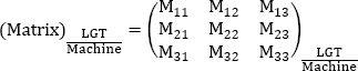
Consequently, the coordinates (Xlgt, Ylgt, Zlgt) in the local geographic trihedron are written using the following transfer matrix from the coordinates (Xe, Ye, Ze) in the aircraft trihedron:

and:
with:
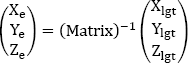
The inverse matrix, which makes it possible to pass from the aircraft trihedron to the local geographical trihedron, is symmetrical compared to the diagonal:
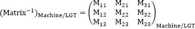
where:
M11 = cos Ψ ∗ cos θ
M12 = − sin Ψ ∗ cos ϕ + cos Ψ ∗ sin θ ∗ sin ϕ
M1ଷ = sin Ψ ∗ sin ϕ + cos Ψ ∗sin θ ∗ cos ϕ
M21 = sin Ψ ∗ cos θ
M22 = cos Ψ ∗ cos ϕ + sin Ψ ∗ sin θ ∗ sin ϕ
M23 = − cos Ψ ∗ sin ϕ + sin Ψ ∗ sin θ ∗ cos ϕ
M31 = − sin θ
M32 = cos θ ∗ sin ϕ
M33 = cos θ ∗ cos ϕ

Figure 4.4. Position of the aircraft trihedron with respect to the reference trihedron. The planes (G, x0, y0) and (G, xh, yh) are parallel. In black: the reference trihedron (G, x0, y0, z0) with Gz0 directed towards the center of the Earth (axis of gravity). The machine trihedron is represented by (G, x1, y1, z1). For a color version of this figure, see www.iste.co.uk/louis/flight.zip
4.5.2. Position of the aerodynamic trihedron with respect to the terrestrial trihedron
The reference trihedron is the earth trihedron redefined with respect to the center of the Earth (G, X0, Y0, Z0).
The aerodynamic trihedron (G, XA, YA, ZA) is usually identified by three classical angles compared to the reference trihedron.
For the change of trihedron, we carry out the three classic rotations:
- – the aerodynamic route or the aerodynamic azimuth χa: rotation around axis Z0, which brings GX0 into GXh and GY0 into GYh, in the vertical plane passing from GZ0;
- – the aerodynamic slope γa around the axis GYh, which brings GXh into GXa and GZ0 into GZf;
- – the rotation μa around the axis GXa, which brings GYh into GYa and GZf into GZa.
Therefore, the coordinates (XA, YA, ZA) in the terrestrial trihedron are written using the following transfer matrix from the coordinates (X0, Y0, Z0) in the terrestrial trihedron:
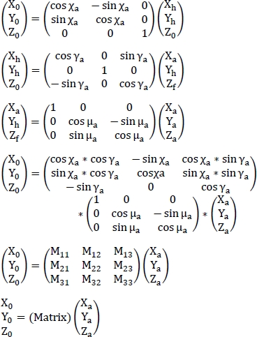
and:
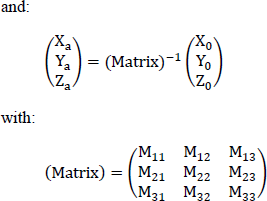
with:
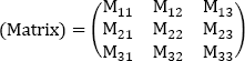
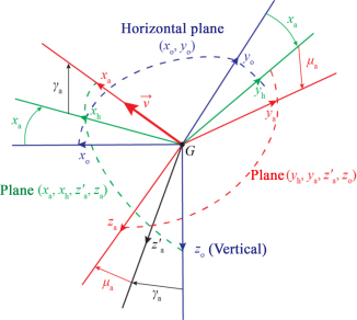
Figure 4.5. Position of the aerodynamic trihedron with respect to the terrestrial trihedron. In blue: the terrestrial trihedron (G, x0, y0, z0), Gz0 depends on the gravity; in red: the trihedron of the aerodynamic speed (G, xa, ya, za). For a color version of this figure, see www.iste.co.uk/louis/flight.zip
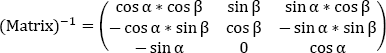
The inverse matrix, which makes it possible to pass from the aircraft trihedron to the terrestrial trihedron, is symmetrical with respect to the diagonal:
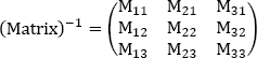
where:
M11 = cos χa ∗ cos γa
M12 = − sin χa ∗ cos μa + cos χa ∗ sin γa ∗ sin μa
M13 = sin χa ∗ sin μa + cos χa ∗ sin γa ∗ cos μa
M21 = sin χa ∗ cos γa
M22 = cos χa ∗ cos μa + sin χa ∗ sin γa ∗ sin μa
M23 = − cos χa ∗ sin μa + sin χa ∗ sin γa ∗ cos μa
M31 = − sin γa
M32 = cos γa ∗ sin μa
M33 = cos γa ∗ cos μa
4.5.3. Position of the aircraft trihedron in relation to the aerodynamic speed trihedron
The aerodynamic speed trihedron of the aircraft (G, Xva, Yva, Zva) is defined as follows:
- – GXva is driven by the aerodynamic speed;
- – GZva ┴ GXva is located in the plane of symmetry of the aircraft and oriented ˃ 0 towards the belly of the aircraft (towards the center of the Earth);
- – GYva completes the direct trihedron.
Axis GZva being located by definition in the aircraft symmetry plane (G, Xe, Ze), just two angles are enough to achieve the change of reference:
- – the incidence α is the angle of the axis (GXe) with the plane (G, Xva, Yva) of the aerodynamic trihedron;
- – the slip β is the angle of the axis (GXva) with the plane of symmetry (G, Xe, Ze).
Moreover:
- – α ˃ 0 when (G,Xe) is above the plane;
- – β ˃ 0 if the projection of the speed vector is positive on the axis (G, Ye).
Therefore, the coordinates (X0, Y0, Z0) in the reference trihedron are written using the following transfer matrix from the coordinates (Xe, Ye, Ze) in the aircraft trihedron:


and:

with the matrix which makes it possible to pass from the aerodynamic speed trihedron to the aircraft trihedron:

The inverse matrix, which makes it possible to pass from the aircraft trihedron to the aerodynamic speed trihedron, is symmetrical with respect to the diagonal:
The total angle of attack is the angle αT between axis GXe of the aircraft and axis GXa of the aerodynamic speed.
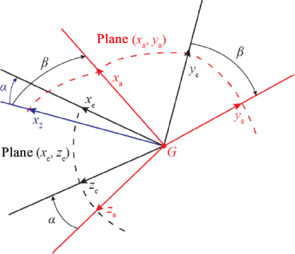
Figure 4.6. Position of the aerodynamic trihedron with respect to the aircraft trihedron. In red: the aerodynamic speed trihedron (G, xa, ya, za); in black: the machine trihedron (G, xe, ye, ze); in blue: the projection α of the axis (G, xe) on the plane (G, xa, ya); in black: the projection of the axis (G, xa) on the plane (G, xe, ze). Plane (G, xa, ya) comprises points (x2, xa, ye, ya); plane (G, xe, ze) comprises points (za, ze, x2, xe). For a color version of this figure, see www.iste.co.uk/louis/flight.zip
4.5.4. Position of the aircraft trihedron in relation to the balance trihedron
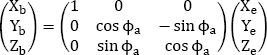
The position of the aircraft trihedron (G, Xe, Ye, Ze) with respect to the balance trihedron (G, Xb, Yb, Zb) is given by the equations in Figure 4.7.
Consequently, the coordinates (Xe,Ye,Ze)in the aircraft trihedron can be written thanks to the following transfer matrix from the coordinates (Xb, Yb, Zb) in the balance trihedron:


Figure 4.7. Position of the aircraft trihedron in relation to the balance trihedron
COMMENTS ON FIGURE 4.7.–
- – Xe = xb;
- – Ye = Yb ∗ cos ϕa – Zb ∗ sin ϕa;
- – Ze = Yb ∗ (− sin ϕa) + Zb ∗ cos ϕa.
The inverse matrix (matrix)–1, which makes it possible to pass from the balance trihedron to the aircraft trihedron, is symmetrical with respect to the diagonal:
The flight coefficients are given by the following tables:
CXb = Cxe
CYb = Cye ∗ cos ϕe – CZe ∗ sin ϕe
CZb = Cye ∗ sin ϕe + Cze ∗ cos ϕe
CLb = CLe
CMb = CMe ∗ cos ϕe – CNe ∗ sin ϕe
CNb = CMe ∗ sin ϕe + CNe ∗ cos ϕe
Cxe = Cxb
Cye = Cyb ∗ cos ϕe + Czb ∗ sin ϕe
Cze = Cyb ∗ (−sin ϕe) + Czb ∗ cos ϕe
CLe = CLb
CMe = CMb ∗ cos ϕe + CNb ∗ sin ϕe
CNe = CMb ∗ (−sin ϕe) + CNb ∗ cos ϕe
The aerodynamic coefficients obtained in the wind tunnel are the coefficients generally defined in [0°, 45°].
4.5.5. Position of the terrestrial trihedron in relation to the local geographic trihedron
The meanings of the parameters used are as follows:
- – Ω: the speed of rotation of the Earth with respect to an absolute reference;
- – λM: the difference between the latitude of the aircraft and the latitude of the origin of the test track;
- – λct: the latitude of the origin of the test track;
- – GM: the difference between the longitude of the aircraft and the longitude of the origin of the test track.
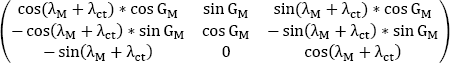
The position of the aircraft in the land reference is given by the following transfer matrix using two successive rotations. The axis (GZlgt) being located by definition in the aircraft plane of symmetry (G, Xe, Ze), just two angles are enough to achieve the change of reference:
- – the latitude (λM + λct) is the angle of the axis (GXe) reduced to (GXlgt) with the plane (G, Xter, Yter) of the aerodynamic trihedron;
- – the longitude (GM) is the angle of the axis (GXe) reduced to (GXlgt) with the plane of symmetry (G, Xter, Yter).
When (GXlgt)is above the plane, (λM + λct) ˃ 0. If the projection of the speed vector is positive on the axis (GYlgt), (GM) ˃ 0.
Therefore, the coordinates (Xter, Yter, Zter) d in the terrestrial trihedron are written using the following transfer matrix from the coordinates (Xlgt, Ylgt, Zlgt) in the local geographic trihedron:
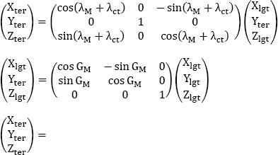

The matrix that makes it possible to pass from the terrestrial trihedron to the local geographical trihedron is therefore:
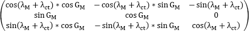
The inverse matrix that makes it possible to pass from the local geographical trihedron to the terrestrial trihedron is symmetrical relative to the diagonal: