9
Quaternion Methods
9.1. Goal
The problem posed in this chapter is that of simplifying the calculation of the change of axes by not making use of Euler angles, thereby avoiding the calculation of trigonometric lines and at the same time excluding any angular indeterminacy (a problem which arises from using Euler angles).
A method for changing axes that uses only rational functions can save calculation time (in the case of ground resources) or lead to a reduction in the size of the calculator (in the case of on-board equipment).
Euler angles are widely used in mechanics and astronomy. They are useful when explicit knowledge of a mobile around its center of gravity is required. In addition, they correspond to degrees of freedom materialized physically.
Olinde-Rodrigues’s formulas make it possible to simplify and reduce the number of axis change calculations when explicit knowledge of angles Ψ, θ and Φ is not required. They use the direction of the instantaneous axis of rotation (two parameters) and the angle of rotation V around this axis as three independent parameters.
9.2. Reminder of the axis change formulas using Euler angles
The most general change of axes corresponds to a certain displacement. It consists of a translation (movement of the center of gravity) and of a rotation around an axis passing through the center of gravity (movement around the center of gravity, i.e. around the instantaneous axis of rotation).
If we are only interested in the rotation around the center of gravity, and thus if Ω is the instantaneous speed vector of rotation:
![]() denote the unit vectors of the axes ox, oy and oz deduced from the fixed trihedron (O, X, Y, Z) from a rotation of an angle V around the instantaneous axis of rotation (Δ) passing through O.
denote the unit vectors of the axes ox, oy and oz deduced from the fixed trihedron (O, X, Y, Z) from a rotation of an angle V around the instantaneous axis of rotation (Δ) passing through O.
![]() designate the unit vectors of axes OX, OY and OZ.
designate the unit vectors of axes OX, OY and OZ.
By proceeding in order to the three rotations corresponding to the angles Ψ, θ and Φ, we obtain the results explained in Chapter 5, section 5.5.1.
The integration of Ψ, θ and ϕ, knowing p, q and r and the Euler angles at time T, allows us to deduce the values of the Euler angles at the instant T + ΔT.
The use of computer programs involves trigonometric line subroutines and requires solving the problem of determining the angles when θ = 90°.
9.3. Olinde-Rodrigues’s formulas: definition of quaternions
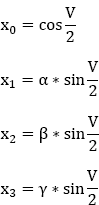
Olinde-Rodrigues’s formulas express the nine director cosines as a rational function of three parameters directly related to the amplitude V of the rotation and to the director cosines of its axis (α, β, γ).
Let V therefore be the amplitude of the rotation, bringing the point M to M’, and let H be the foot of the perpendicular lowered by Ω on MM’.
The plane (ωMM’) is normal to the axis of rotation (Δ) of unit vector u.
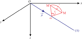
Figure 9.1. Rotation axis Δ. For a color version of this figure, see www.iste.co.uk/louis/flight.zip
By letting:
we obtain:
Thus:
with:
since:

from which we obtain:

On the other hand:
According to equation [9.1], we can write:
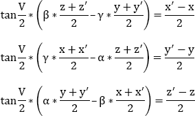
Hence, the linear relations linking x׳, y׳ and z׳ to x, y and z are:

The resolution of the system gives:

from which we obtain:

By letting:
we obtain:
Thus:
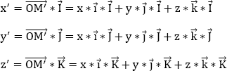
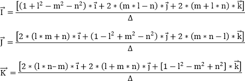
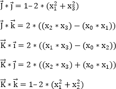
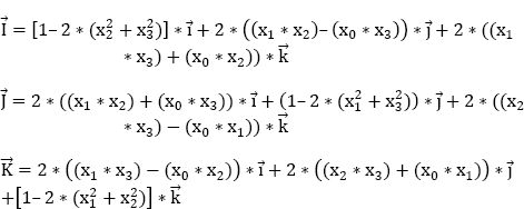
The nine directing cosines of the vectors ![]() in the trihedron
in the trihedron ![]() are given by the following equations:
are given by the following equations:
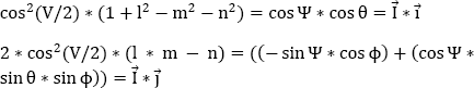
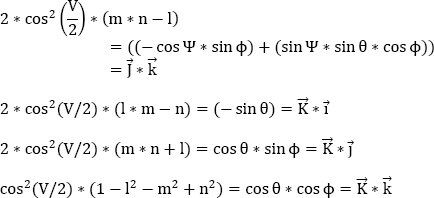
If we compare them to the formulas obtained for the directing cosines of ![]() with the Euler angle method (see section 4.5.1), we find:
with the Euler angle method (see section 4.5.1), we find:

By letting:
we have:
Having knowledge of every moment of the parameters (x0,x1,x2,x3) allows the Euler angles (Ψ, θ, ϕ) to be calculated using equations [9.4]–[9.6].
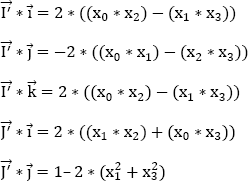
In order to determine the correspondence between the parameters(x0,x1,x2,x3)and the Euler angles (Ψ, θ, ϕ), it is interesting to go through a reference trihedron from the previous one (O, X, Y, Z) with a rotation of + 90° around the axis ![]() Let (O,X׳,Y׳,Z׳)be this new reference trihedron. We have:
Let (O,X׳,Y׳,Z׳)be this new reference trihedron. We have:
We have:
The unit vector of the instantaneous axis of rotation is written:
We obtain:
If (Ψ׳, θ׳, ϕ׳) designate the Euler angles in this new trihedron (O, X׳, Y׳, Z׳), then we have the following identity:
Using the duplication formulas in trigonometry:
cos(2a) = cos2(a)– sin2(a) = 2∗cos2(a)–1 = 1–2sin2(a)
we obtain:
Thus:
by letting:
From equation [9.8], we obtain:
and thus:

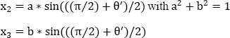
by letting:
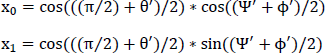
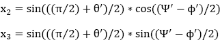
x0 = c ∗ cos(((π/2) + θ׳)/2)
with:

By using these new expressions of (x0, x1, x2, x3) in equation [9.9] and by identifying them with the expressions of the directing cosines as a function of the angles (Ψ׳, θ׳, ϕ׳), we obtain:
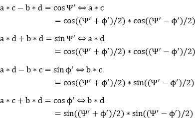
This results in:
a = cos((Ψ׳ − ϕ׳)/2)
b = sin((Ψ׳ − ϕ׳)/2)
c = cos((Ψ׳ + ϕ׳)/2)
d = sin((Ψ׳ + ϕ׳)/2)
From equations [9.10] and [9.11], we can deduce that:
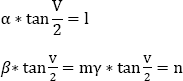
Equation [9.12] is useful to initialize the parameters (x0,x1,x2,x3).
In Figure 9.2, α, β and γ represent the directing cosines of the instantaneous axis of rotation with respect to the trihedron (O, X, Y, Z) deduced from the trihedron (O, X׳, Y׳, Z׳), with respect to which the angles are related (Ψ׳,θ׳,ϕ׳) by a rotation of (−π/2) around ![]()

Figure 9.2. Quaternion trihedrons
The directing cosines of the instantaneous axis of rotation in the same reference trihedron as that used for the Euler angles (Ψ׳,θ׳,ϕ׳) are (–γ, + β, +α).
To obtain the differential equations which define the evolution over time of the terms (x0, x1, x2, x3) of the quaternion allowing the calculation of the change of axes, we can proceed as for the Euler method:

From equation [9.8], we can write:
By differentiating equation [9.13] and using the derivative equation [(u∗v)׳ = (u׳ ∗ v) + (u ∗ v׳)], we obtain:
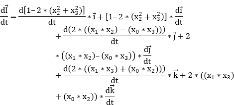
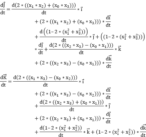
According to equation [9.14], we obtain:

The three components following ![]() and
and ![]() must be zero.
must be zero.
Focusing on the axis ![]() let:
let:

and let:


Focusing on the axis ![]() let:
let:
and let:
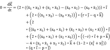
Focusing on the axis ![]() let:
let:

and let:

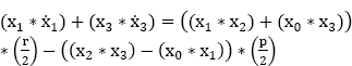
By deriving the equation ![]() we obtain:
we obtain:
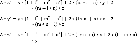
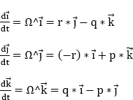
The differential system is written:

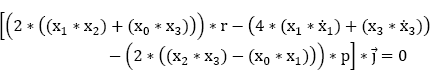
By summing the first three parts of equation [9.19] and comparing them to the fourth part, we obtain:
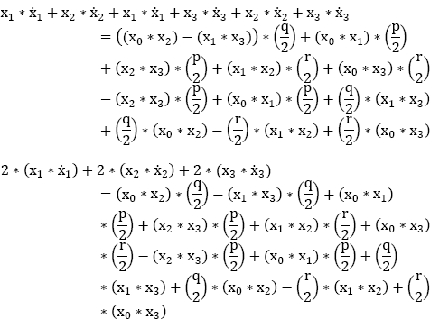
We then obtain:
and:

Thus:

Now that we know x, we need to find ![]()
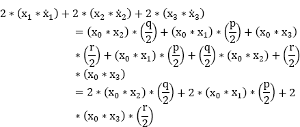
We add the first and the second parts of equation [9.19] and subtract the third part:
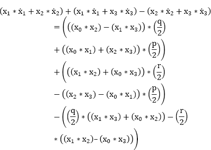

We then add the first and the third parts of equation [9.19] and subtract the second part:


We then add the second and third parts of equation [9.19] and subtract the first part:

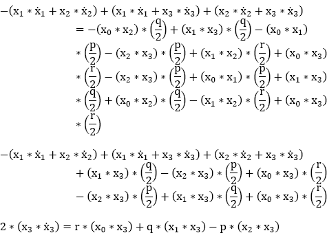
In summary:
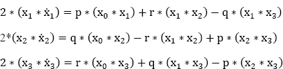
This system of three equations is equivalent to:
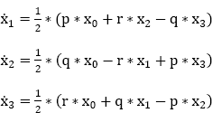
Equations [9.20] and [9.21] make it possible to use step-by-step numerical integration to obtain the new values of the four parameters (x0, x1, x2, x3)at each step of the calculation.
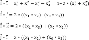
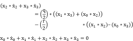
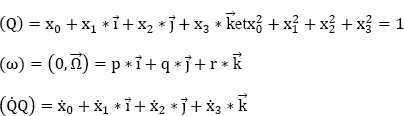
NOTE.– The four parameters (x0, x1, x2, x3) are not independent. In accordance with the first part of equation [9.8], we have ![]()
![]()
The inaccuracies resulting from the separate integration of the four differential equations have to be corrected by possibly “renormalizing” the four parameters at each calculation step.
The four differential equations are of the first order, with non-constant coefficients, but they do not involve the trigonometric lines.
There is no longer a problem of angular determination when the three Euler angles (Ψ, θ, ϕ) approach or pass through 0° and/or 90°. The physical representation of the parameters (x0,x1,x2,x3)is highlighted, because:
α, β and γ represent the directing cosines of the instantaneous axis of rotation with respect to the trihedron (O, X, Y, Z) deduced from the trihedron (O, X׳, Y׳, Z׳), and V is the instantaneous amplitude of the rotation (in the reference trihedron of Euler angles (Ψ, θ, ϕ). The directing cosines of the instantaneous axis of rotation are (−γ, +β, +α)).
Finally, with (Q) denoting the unitary quaternion defined by (x0,x1,x2,x3) and (Ω) the quaternion representing the instantaneous vector ![]() of rotation, we can write:
of rotation, we can write:
with:
See Laisant (1877) and De Casteljau (1997).