
Standard Operation in Fast, Error-Free Environment
Assumptions in This Section
This section describes how messages are transferred in a “perfect” environment, but with no optional optimizations being used. It assumes the following base-line set of conditions:
No delay in request packet delivery. The request packets issued by the requester QP's SQ Logic make their way to the responder QP's RQ Logic in an expeditious manner.
Quick generation of responses. The responder QP's RQ Logic processes each request packet rather quickly and issues the corresponding response packet back to the requester QP.
No delay in response packet delivery. The response packet makes its way back to the requester QP's SQ Logic quickly.
No packets lost. No request or response packets are “lost” in the fabric due to errors of any sort.
No error conditions are encountered, neither within the two CAs nor in the packet flight path.
No Ack coalescing. The responder QP's RQ Logic does not implement Acknowledge coalescing (more on this later). In other words, the responder QP's RQ Logic is designed to issue a response (or, possibly, multiple responses in the case of an RDMA Read request) for each request packet received.
Messages to Be Sent Defined by SQ WQEs
When software associated with a HCA wishes to send a message to a remote CA, it posts a WR to the SQ of the local QP that it is associated with. This is accomplished by executing the Post Send Request verb. Refer to “Posting a WR to the SQ” on page 260 for a description of the WR.
Maximum Data Payload Defined by PMTU
The maximum amount of data that can be transferred in a packet between two ports is defined by the PMTU for that path (see “Maximum Data Payload Size” on page 42). Both of the RC QPs were programmed with the PMTU during QP setup.
Remote RQ Start ePSN = Local SQ Start PSN
Refer to Figure 17-1 on this page and Figure 17-2 on page 364. When the two QPs are set up, a Start PSN is assigned to each QP's SQ Logic. The PSN is a 24-bit number, so the SQ Logic's Start PSN can be any number between 000000h and FFFFFFh (a 224, or 16M, range).
Figure 17-1. Relationship of SQ Start PSN and RQ ePSN at Startup

Figure 17-2. SQ Logic's View of PSN in Ack Packets

Refer to Figure 17-3 on page 365. The RQ Logic ePSN (expected PSN) in each of the two QPs are each assigned a PSN that is equal to the remote QP's SQ Logic Start PSN. As the SQ Logic generates request packets, it inserts the PSN in each request packet's BTH:PSN field (see Figure 17-4 on page 365). At the receiving end, the RQ Logic compares the PSN in each incoming request packet to see if it matches its ePSN (expected PSN). In this manner, the RQ Logic can determine if any request packets are lost in transit.
Figure 17-3. RQ Logic's View of PSN in Request Packets

Figure 17-4. Base Transport Header Fields

Message Transfer Overview Example
Refer to Figure 17-12 on page 383. In this example, a series of message transfer WRs have been posted to a RC QP's SQ. The SQ Logic processes these WQEs one at a time starting with the earliest posting.
Figure 17-12. Message Transfer Overview

Some Definitions
The following definitions are important in the following subsections:
cPSN. Current PSN is the PSN inserted in the request packet currently being transmitted.
nPSN. This is the PSN value that will be inserted in the next request packet transmitted to the remote QP's RQ Logic. Initially, nPSN = Start PSN. For each subsequently transmitted request packet, nPSN is calculated as follows:
- If the request packet just transmitted was an RDMA Read request packet, nPSN = cPSN + the number of expected RDMA Read response packets.
- If the request packet just transmitted was anything other than an RDMA Read request, nPSN = cPSN + 1.
ePSN. Expected PSN is the PSN the RQ Logic expects to see in the next request packet that is received from the remote QP's SQ Logic.
Assumptions Made in the Example
The example makes the following assumptions:
The QP (and its remote companion QP) have just been set up and no messages have been exchanged yet.
The initial PSN value assigned to this QP's SQ Logic Start PSN and to the remote QP's RQ Logic ePSN is 201.
Initially, the SQ Logic's nPSN = its assigned Start PSN value.
The series of subsections that follow provide a brief description of the first six message transfers.
SQ WQE 0: Send Operation
The Request Packets
The requester QP's SQ Logic uses the SQ WQE's Gather Buffer List to read the message data from the CA's local memory and, based on the PMTU, transmits a series of five request packets (see Figure 17-5 on page 367) to the responder QP's RQ Logic. This consists of:
- One request packet with a BTH:Opcode of “Send First” (see the Opcode field in Figure 17-4 on page 365) and a data payload field containing PMTU bytes. The BTH:PSN value is 201.
- Three request packets, each with a BTH:Opcode of “Send Middle” and a data payload field containing PMTU bytes. The BTH:PSNs in the three packets are 202 through 204.
- One request packet with a BTH:Opcode of “Send Last” and a data payload field containing the remaining message data (somewhere between one and PMTU bytes). The BTH:PSN value is 205. Note that the final request packet may or may not contain the optional 32-bit immediate data item. If it does, the final request packet contains the ImmDtETH.
Figure 17-5. Send Request Packet Format

nPSN Update
Each time the SQ Logic transmits a request packet that is not an RDMA Read request packet, it updates its nPSN as follows: nPSN = cPSN + 1.
RQ WQE Defines Where Data Is to Be Written
A message Send operation supplies the destination QP's RQ Logic with neither the start address of where the data is to be written nor the transfer length. For this reason, the RQ Logic on the receiving end must access the Scatter Buffer List in its next RQ WQE to determine where to write the incoming message data in its local memory. The RQ Logic writes each request packet's data payload into memory using the Scatter Buffer List supplied in the top RQ WQE.
The RQ Logic recognizes the end of the operation by the “Send Last” or “Send Only” BTH:Opcode plus the data payload length specified in the final request packet.
Request Packet PSN Verification
In the following manner, the destination QP's RQ Logic verifies that the five request packets are received in order and that none are missing (refer to Figure 17-3 on page 365):
- The first request packet is received with a PSN of 201. This matches the RQ Logic's ePSN. Because the request packet is not an RDMA Read request packet (“SQ WQE 3: RDMA Read Operation” on page 375 describes how this situation is treated), the RQ Logic increments its ePSN to 202.
- As each of the message's remaining four request packets are received, the packet's PSN is compared to the ePSN and they are equal. The ePSN is incremented by one. All of the request packets are received in order and none are missing.
- After the last request packet for this message Send operation has been received and its PSN verified, the ePSN = 206.
The Ack Packets
For each of the five Send request packets received, the responder QP's RQ Logic responds with an Ack packet (see Figure 17-6 on page 369) containing the same PSN as the corresponding request packet. The Syndrome field in the AETH indicates whether this is a positive Ack or a negative Ack (a Nak). Refer to Table 17-3 on page 370. Syndrome[7:5] = 000b indicates a positive Ack. In this discussion, it is assumed that all of the Acks received are positive Acks, indicating that no error has occurred.
Figure 17-6. Ack Packet Format

Refer to Figure 17-2 on page 364. The BTH:PSN field is a 24-bit field, so a request packet's PSN can be any number between 000000h through FFFFFFh. The SQ Logic remembers the last 8M request packet PSNs. As each request packet is transmitted, the SQ Logic's range of unAck'd PSNs grows upwards. As each corresponding Ack packet is received by the SQ Logic and its PSN is verified, the SQ Logic grows the upper end of its Ack'd PSN range upwards.
Maximum Number of UnAck'd Request Packets
The maximum number of unAck'd request packets that the SQ Logic is permitted to launch into the fabric is 223 (8M; refer to “Maximum Number of Outstanding Requests” on page 208). If the SQ Logic reaches this point of advancement, it would have to stall until it starts receiving Acks back for outstanding requests issued earlier.
RQ WQE Completion
When the RQ Logic has accepted the final request packet and has committed to write its data payload to local memory, the RQ WQE is retired and a RQ CQE is created to record the completion status of the inbound message written to local memory. Note that the final request packet may or may not contain the optional 32-bit immediate data item. If it does, the final request packet includes the ImmDtETH and the immediate data value it contains is stored in the CQE.
SQ WQE Completion
When the SQ Logic has received and verified the final Ack packet's PSN, the SQ WQE is retired and a SQ CQE is created to record the completion status of the message transmit operation.
| Bit 7 | Bits 6:5 | Bits 4:0 | Definition |
|---|---|---|---|
| 0 | 00 | CCCCC |
|
| 0 | 01 | TTTTT | RNR Nak. TTTTT = the minimum amount of time the requester QP's SQ Logic must wait before retrying the request. It's encoding can be found in Table 17-6 on page 411. |
| 0 | 10 | XXXXX | Reserved. |
| 0 | 11 | NNNNN |
|
| AETH[4:0] | Definition |
|---|---|
| 00000 | PSN Sequence Error. |
| 00001 | Invalid Request. |
| 00010 | Remote Access Error. |
| 00011 | Remote Operational Error. |
| 00100 | Invalid RD Request. |
| 00101–11111 | Reserved. |
SQ WQE 1: Send Operation
The Request Packets
The requester QP's SQ Logic uses the SQ WQE's Gather Buffer List to read the message data from the CA's local memory, and, based on the PMTU, transmits a series of 52 request packets to the responder QP's RQ Logic. This consists of:
- One request packet with a BTH:Opcode of “Send First” and a data payload field containing PMTU bytes. The BTH:PSN value is 206.
- 50 request packets, each with a BTH:Opcode of “Send Middle” and a data payload field containing PMTU bytes. The BTH:PSNs in the 50 packets are 207 through 256.
- One request packet with a BTH:Opcode of “Send Last” and a data payload field containing the remaining message data (somewhere between one and PMTU bytes). The BTH:PSN value is 257. Note that the final request packet may or may not contain the optional 32-bit immediate data item. If it does, the final request packet contains the ImmDtETH.
nPSN Update
Each time the SQ Logic transmits a request packet that is not an RDMA Read request packet, nPSN = cPSN + 1.
RQ WQE Defines Where Data Is to Be Written
The RQ Logic on the receiving end must access the Scatter Buffer List in the next RQ WQE to determine where to write the incoming message data in its local memory. The RQ Logic writes each request packet's data payload into memory using the Scatter Buffer List supplied in the top WQE of the RQ. The RQ Logic recognizes the end of the operation by the “Send Last” or “Send Only” BTH:Opcode plus the data payload length specified in the final request packet.
Request Packet PSN Verification
In the following manner, the destination QP's RQ Logic verifies that the 52 request packets are received in order and that none are missing (refer to Figure 17-3 on page 365):
- The first request packet is received with a PSN of 206. This matches the RQ Logic's ePSN. Because the request packet is not an RDMA Read request packet, the RQ Logic increments its ePSN to 207.
- As each of the remaining request packets are received, the packet's PSN is compared to the ePSN and they are equal. The ePSN is incremented by one. All of the request packets are received in order and none are missing.
- After the last request packet for this message Send operation is received and its PSN verified, the ePSN is = 258.
The Ack Packets
For each of the 52 request packets that are received, the responder QP's RQ Logic responds with an Ack packet containing the same PSN as the request packet. As each corresponding Ack packet is received by the SQ Logic and its PSN is verified, the SQ Logic grows the upper end of its Ack'd PSN range upwards (see Figure 17-2 on page 364).
RQ WQE Completion
When the RQ Logic has accepted the final request packet and committed to write its data payload to local memory, the RQ WQE is retired and a RQ CQE is created to record the completion status of the inbound message written to local memory. Note that the final request packet may or may not contain the optional 32-bit immediate data item. If it does, the final request packet includes the ImmDtETH and the immediate data value it contains is stored in the CQE.
SQ WQE Completion
When the SQ Logic has received the final Ack packet and verified its PSN, the SQ WQE is retired and a SQ CQE is created to record the completion status of the message transmit operation.
SQ WQE 2: RDMA Write Operation
The Request Packets
The requester QP's SQ Logic uses the SQ WQE's Gather Buffer List to read the message data from the CA's local memory and, based on the PMTU, transmits a series of nine request packets (see Figure 17-7 on page 374) to the responder QP's RQ Logic. This consists of:
- One request packet with a BTH:Opcode of “RDMA Write First” and a data payload field containing PMTU bytes. The BTH:PSN value is 258. Only the first request packet of the RDMA Write message contains the RETH header.
- Seven request packets, each with a BTH:Opcode of “RDMA Write Middle” and a data payload field containing PMTU bytes. The BTH:PSNs in the seven packets are 259 through 265. The middle packets of the message do not contain the RETH header.
- One request packet with a BTH:Opcode of “RDMA Write Last” and a data payload field containing the remaining message data (somewhere between one and PMTU bytes). The BTH:PSN value is 266. The last packet of the message does not contain the RETH header. Note that the final request packet may or may not contain the optional 32-bit immediate data item. If it does, the final request packet contains the ImmDtETH.
Figure 17-7. RDMA Write Request Packet Format

nPSN Update
Each time the SQ Logic transmits a request packet that is not an RDMA Read request packet, nPSN = cPSN + 1.
No RQ WQE Required
The first RDMA Write request packet's RETH contains the following information obtained from the SQ WQE:
- -
VA.
Start virtual memory address to which the data is to be written in the destination CA's local memory.
- -
R_Key.
The Remote Access Key required to gain access to the region or window in the destination CA's memory.
- -
Transfer length.
In bytes.
Because the first request packet of an RDMA Write supplies the start address and length of the write, the RQ Logic on the receiving end does not need to access the top RQ WQE to determine where to write the incoming message data in its local memory. Instead, the RQ Logic writes each request packet's data payload into memory using the address information supplied in the first request packet.
Request Packet PSN Verification
In the following manner, the destination QP's RQ Logic verifies that the nine request packets are received in order and that none are missing (refer to Figure 17-3 on page 365):
- The first request packet is received with a PSN of 258. This matches the RQ Logic's ePSN. Because the request packet is not an RDMA Read request packet, the RQ Logic increments its ePSN to 259.
- As each of the remaining request packets are received, the packet's PSN is compared to the ePSN and they are equal. The ePSN is incremented by one. All of the request packets are received in order and none are missing.
- After the last request packet for this RDMA Write operation is received and its PSN verified, the ePSN = 267.
The Ack Packets
See Figure 17-6 on page 369. For each of the nine request packets received, the responder QP's RQ Logic responds with an Ack packet containing the same PSN as the request packet. It also writes the request packet's data payload into memory using the address information supplied in the first request packet's RETH header. As each corresponding Ack packet is received by the SQ Logic and its PSN is verified, the SQ Logic grows the upper end of its Ack'd PSN range upwards (see Figure 17-2 on page 364).
No CQE Posted on Receiving End
When the write has been completed on the responder end, no CQE is created (because no RQ WQE was used). That means there is no signal to software on the responder end that the inbound RDMA Write has completed and a message is present in local memory to be processed. Software on the sender's end could have forced a RQ CQE to be created by performing an RDMA Write With Immediate, rather than an RDMA Write Without Immediate. For more information, see “RDMA Write Operation” on page 90.
SQ WQE Completion
When the SQ Logic has received and verified the final Ack packet's PSN, the SQ WQE is retired and a SQ CQE is created to record the completion status of the message transmit operation.
SQ WQE 3: RDMA Read Operation
The Request Packet (there is only one)
A single RDMA Read request packet (see Figure 17-8 on page 377) will be transmitted to the responder QP's RQ Logic. The RDMA Read request packet contains the following items obtained from the SQ WQE:
- -
VA.
Start virtual memory address from which the data is to be read in the destination CA's local memory.
- -
R_Key.
The Remote Access Key required to gain access to the region or window in the destination CA's memory.
- -
Transfer length.
In bytes. In this case, based on the PMTU, this will result in the return of six RDMA Read response packets containing the requested read data.
- PSN = 267.
Figure 17-8. RDMA Read Request Packet Format

nPSN Update
Each time the SQ Logic transmits an RDMA Read request packet, nPSN = cPSN + the number of expected RDMA Read response packets. The next request packet transmitted will therefore have a PSN of 273.
No RQ WQE Required
Because all of the information necessary to perform the operation is supplied in the request packet, the RQ Logic on the receiving end does not need to access the top RQ WQE to determine where to perform the operation in its local memory. The RDMA Read request packet is latched into a special queue within the RQ Logic that handles incoming RDMA Read and Atomic requests.
Request Packet PSN Verification
Refer to Figure 17-3 on page 365. The destination QP's RQ Logic verifies that the request packet received has a PSN = its ePSN (267). Because this is an RDMA Read request packet, the RQ Logic updates its ePSN as follows:
ePSN = request packet PSN (267) + number of RDMA Read response packets that will be returned to the requester (based on the PMTU, 6 response packets will be returned) = 273. The next request packet received should therefore have a PSN of 273.
The Response Packets
In response, the RQ Logic reads the requested read data from local memory and returns it in a series of six RDMA Read response packets (see Figure 17-9 on page 377). The BTH:PSNs in the six packets are 267 through 272. As each RDMA Read response packet is received by the SQ Logic and its PSN is verified, the SQ Logic grows the upper end of its Ack'd PSN range upwards (see Figure 17-2 on page 364). The number of RDMA Read response packets it takes to return the requested read data is determined by the PMTU:
The PSN in the first RDMA Read response packet returned is the same as the PSN in the RDMA Read request packet (267). Its opcode is “RDMA Read Response First.”
The first (or only) response packet contains the AETH (Ack ETH):
- A positive Ack in the AETH (see Figure 17-6 on page 369 and Table 17-3 on page 370) of the first response packet of a multi-response RDMA Read implicitly Acks all unAck'd requests issued before the RDMA Read request was issued.
- A positive Ack in the AETH of the only RDMA Read response packet of a single-response RDMA Read implicitly Acks all unAck'd requests issued before the RDMA Read request was issued. It also explicitly Acks the RDMA Read request.
The PSNs in each of the remaining RDMA Read response packets returned = PSN of previous response packet + 1. The four middle packets have an opcode of “RDMA Read Response Middle.”
The last response packet of a multi-response RDMA Read contains an AETH and its opcode is “RDMA Read Response Last.” A positive Ack explicitly Acks the RDMA Read request.
The data payload field of the first five RDMA Read response packets contains PMTU bytes.
The data payload field of the final RDMA Read response packet contains the remaining data (somewhere between one and PMTU bytes).
Figure 17-9. RDMA Read Response Packet Format

Returned Read Data Written to Memory
On receipt of each of the RDMA Read response packets, the SQ Logic accesses the SQ WQE's Scatter Buffer List to determine where to write the packet's data payload (i.e., the message data) in the CA's local memory.
No CQE Posted on Receiving End
When the RDMA Read has been completed on the responder end, no CQE is created (because no RQ WQE was used). There is no signal to software on the responder end that the inbound RDMA Read has completed.
SQ WQE Completion
When the SQ Logic has received the final RDMA Read response packet and has written its data payload to local memory, the SQ WQE is retired and a SQ CQE is created to record the completion status of the message read operation.
SQ WQE 4: Send Operation
The Request Packet
This is a short message wherein the message length is ≤ PMTU bytes in length. The entire message therefore fits in the data payload field of one request packet. Using the SQ WQE's Gather Buffer List, the SQ Logic reads the message data from the CA's local memory and transmits a single request packet with a BTH:Opcode of “Send Only” and a data payload field containing somewhere between zero and PMTU bytes. The BTH:PSN value is 273. Note that the request packet may or may not contain the optional 32-bit immediate data item. If it does, the request packet contains the ImmDtETH.
nPSN Update
Each time the SQ Logic transmits a request packet that is not an RDMA Read request packet, nPSN = cPSN + 1. The next request packet transmitted will therefore have a PSN of 274.
RQ WQE Defines Where Data to Be Written
The RQ Logic on the receiving end must access the Scatter Buffer List in the next RQ WQE to determine where to write the incoming message data in its local memory. The RQ Logic writes the request packet's data payload into memory using the Scatter Buffer List supplied in the next WQE of the RQ.
The RQ Logic recognizes the end of the operation by the request packet's “Send Only” BTH:Opcode plus the data payload length specified in the request packet.
Request Packet PSN Verification
Refer to Figure 17-3 on page 365. The destination QP's RQ Logic verifies that the PSN of the request packet received = its ePSN of 273. The ePSN is then incremented to 274. The next request packet received should therefore have a PSN of 274.
The Ack Packet
The responder QP's RQ Logic responds with an Ack packet containing the same PSN as the request packet. When the Ack packet is received by the SQ Logic and its PSN is verified, the SQ Logic grows the upper end of its Ack'd PSN range upwards by one (see Figure 17-2 on page 364).
RQ WQE Completion
When the RQ Logic has accepted the final request packet and committed to write its data payload to local memory, the RQ WQE is retired and a RQ CQE is created to record the completion status of the inbound message written to local memory. Note that the request packet may or may not contain the optional 32-bit immediate data item. If it does, the request packet includes the ImmDtETH and the immediate data value it contains is stored in the CQE.
SQ WQE Completion
When the SQ Logic has received and verified the final Ack packet's PSN, the SQ WQE is retired and a SQ CQE is created to record the completion status of the message transmit operation.
SQ WQE 5: Atomic Compare and Swap If Equal Operation
The Request Packet (there is only one)
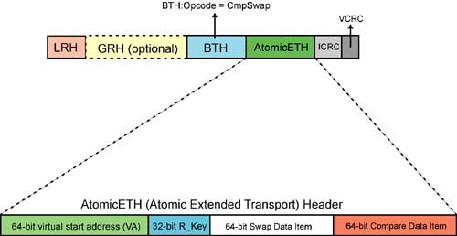
A single Atomic Compare and Swap If Equal request packet (see Figure 17-10 on page 380) is transmitted to the responder QP's RQ Logic. The request packet has a PSN of 274 and its AtomicETH contains this information obtained from the SQ WQE:
- -
VA.
Quadword-aligned start virtual memory address from which the data is to be read in the destination CA's local memory.
- -
R_Key.
The Remote Access Key required to gain access to the region or window in the destination CA's memory.
- -
Compare Data.
The 64-bit data item that is compared to the 64-bit data item read from memory.
- -
Swap Data.
If the read data and the Compare Data are equal, the 64-bit Swap Data item is written back into memory.
Figure 17-10. Atomic Compare and Swap If Equal Request Packet Format
nPSN Update
Each time the SQ Logic transmits a request packet that is not an RDMA Read request packet, nPSN = cPSN + 1. The next request packet transmitted will therefore have a PSN of 275.
No RQ WQE Required
Because all of the information necessary to perform the operation is supplied in the request packet, the RQ Logic on the receiving end does not need to access the top RQ WQE to determine where to perform the operation in its local memory. The Atomic request packet is latched into a special queue within the RQ Logic that handles incoming RDMA Read and Atomic requests.
Request Packet PSN Verification
Refer to Figure 17-3 on page 365. The destination QP's RQ Logic verifies that the PSN of the request packet received = its ePSN of 274. The ePSN is then incremented to 275. The next request packet received should therefore have a PSN of 275.
The Response Packet
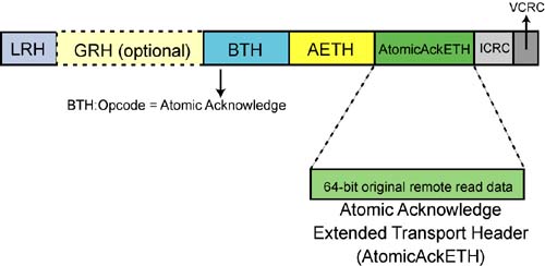
In response, the RQ Logic performs the Atomic RMW operation and returns the original data read from the target memory in a single Atomic Acknowledge packet (see Figure 17-11 on page 381). The data is returned in the packet's AtomicAckETH. The BTH:PSN in the Ack packet is the same as that in the request packet, 274. When the Atomic Acknowledge packet is received by the SQ Logic and its PSN is verified, the SQ Logic grows the upper end of its Ack'd PSN range upwards by one (see Figure 17-2 on page 364). The Atomic Acknowledge packet implicitly acknowledges all outstanding Send and RDMA Write request packets received prior to the Atomic Acknowledge and the AETH in the packet explicitly acknowledges the Atomic request.
Figure 17-11. Atomic Acknowledge Packet Format
No CQE Posted on Receiving End
When the Atomic operation has been completed on the responder end, no CQE is created (because no RQ WQE was used). There is therefore no signal to software on the responder end that the inbound Atomic operation has completed.
SQ WQE Completion
When the SQ Logic has received the Atomic Acknowledge packet, verified its PSN, and has written the returned 64-bit read data item (contained in the AtomicAckETH) to local memory, the SQ WQE is retired and a SQ CQE is created to record the completion status of the operation. The SQ Logic obtained the address to write the returned data item to from the SQ WQE's Scatter Buffer List (which only indicated a single buffer to place the data in).
Request Packets Streamed without Waiting for Each Ack
In the example scenario in Figure 17-12 on page 383, the SQ Logic launches a continuous stream of request packets without pausing to receive the corresponding Ack, RDMA Read response, or Atomic response packets. It launches the five request packets that comprise the first message, the 52 packets that comprise the second message, the nine packets that comprise the third message, and so forth. Eventually, of course, the request packets start arriving at the destination QP's RQ Logic and the RQ Logic starts launching the corresponding stream of Ack, RDMA Read response, and Atomic response packets. At some point, the stream of Ack, RDMA Read response, and Atomic response packets start arriving back at the SQ Logic.
SQ Logic's Transport Timer
The previous paragraph brings up the following question: Is there a limit to how long the SQ Logic will wait for the Ack packets that correspond to the request packets issued? The answer is yes, of course.
Timeouts Exchanged during Connection Establishment
During the exchange of communications establishment messages (REQ, REP, and RTU), the CM that sends the REQ message supplies a Local Ack Timeout value to the remote CA's CM. This 5-bit value is stored in the newly created remote QP's Context and defines the amount of time the remote QP's SQ Logic will wait for a response when it sends a request packet.
The other CA's CM supplies a Target Ack Delay value (defined below) in the communications REP message. The CM that sent the REQ message uses the returned Target Ack Delay to calculate the Local Ack Timeout value to store in the QP Context of its local QP.
The Timeout Formula
The amount of time a RC QP's SQ Logic waits for a response to a request packet is defined by the SQ Logic's Transport Timer, Ttr, and is defined as 4.096µs X 2Local Ack Timeout. It is calculated by the sender of the REQ message using the following formula:
Ttr = 4.096us X 2Local Ack Timeout = (2 X PacketLifeTime) + responder QP's Target Ack Delay,
where:
Local Ack Timeout = 5-bit value.
PacketLifeTime = the maximum amount of time it takes a packet to transit between the source and destination ports. This value is obtained by requesting the PathRecord from the SA.
Target Ack Delay = the amount of time (4.096µs X Target Ack Delay) from the receipt of a request packet until the corresponding Ack packet is transmitted. Target Ack Delay is a 5-bit value.
Ttr begins after a request packet is scheduled for transmission. The Transport Timer doesn't time the return of a response for each individual request packet issued. Rather, it detects the cessation of responses from the responder QP's RQ Logic.
A Timeout condition, To, is detected in no less than Ttr and no more than 4 X Ttr:
The minimum Local Ack Timeout value supported by a CA (other than 0) is defined by the CA vendor. If the Local Ack Timeout value assigned to a QP's SQ Logic is < the minimum supported by the CA, the CA may use its minimum. Setting the SQ Logic's Local Ack Timeout to zero disables the Transport Timer.
On Timeout, Request Packet Is Resent
When a timeout for a given request packet is detected, the requester QP's SQ Logic retries the request (if it has retries remaining).
This portion of the discussion assumes that there are no timeouts or errors of any sort. For a detailed description of the actions taken by the SQ Logic when the Transport Timer times out, refer to “Transport Timer Expiration” on page 392.
SQ Logic Validation of Each Response
For a detailed description of how the SQ Logic validates a response, refer to “SQ Logic's Response Validation” on page 436.