Changing Coordinate Systems
The beginning of this chapter looked at AutoCAD’s rectangular or Cartesian coordinates system from the standpoint of entering coordinates representing points in your drawing (refer to Figure 6.1). You learned about absolute and relative coordinate entry in both rectangular and polar formats. By using the Cartesian coordinates system, and entering either absolute or relative coordinates, you can create highly accurate, detailed drawings of anything.
When you begin a new AutoCAD drawing you are, by default, using a rectangular coordinate system that is called the World Coordinate System, or WCS. In addition to the WCS, you can create other coordinate systems called User Coordinate Systems, or UCSs. They are called UCSs because you, the user, define them to aid you in creating your drawings.
AutoCAD enables you to create your own UCS because this ability often makes defining points for your model easier. For example, suppose you are creating a model of a 3D pyramid, and you need to define points along the surface of one of the pyramid’s faces. This is easily accomplished by aligning a UCS with the face. By doing so, you define an XY plane coincident with the face. After the UCS is properly aligned, it’s just a matter of using the Cartesian coordinate system to create the points along the pyramid’s face, as shown in Figure 6.7. Chapter 27,“Introduction to 3D,” presents additional UCS concepts for use when creating 3D geometry.
Figure 6.7. By properly aligning a User Coordinate System (UCS), developing complex 2D and 3D models becomes easier.

In the next section, you learn about various UCS commands and features you can use to make creating detailed drawings of complex models easier.
World Coordinate System
The World Coordinate System is nothing more than a standard rectangular coordinate system with the origin in the lower-left corner of the screen, a horizontal X-axis running left to right and a Y-axis extending vertically from the bottom to the top of the screen. The Z-axis is perpendicular to both the X- and Y-axes and is considered to extend out toward you in a direction perpendicular to the screen. To identify the WCS and establish its orientation, AutoCAD, by default, places the WCS icon at or near the origin. The WCS icon is shown in Figure 6.8. Its defining characteristic is the “W” appearing on the icon; this tells you that you are in the World Coordinate System.
Figure 6.8. The World Coordinate System (WCS) icon.

Ever since the introduction of the UCSICON it has been plagued with complaints about its functionality and its appearance. With AutoCAD 2000i, the pesky little icon was given a control dialog to help users manipulate it (see Figure 6.9). The control dialog is accessible through the UCSICON command under the Properties option. Within the dialog are controls for displaying the traditional icon look or the new 3D appearance. If you choose the 3D version, you also can control cone or arrow points and the line width of the icon itself. Other options include a size control for the icon and display colors for its use in model space or paper space layouts.
Figure 6.9. The UCS icon properties dialog allows user preference for its display.

User Coordinate Systems
You can create your own coordinate systems called User Coordinate Systems, or UCSs. In a UCS, the origin, as well as the direction of the X-, Y-, and Z-axes can be made to move, rotate, and even align with drawing objects. Although the three axes in a UCS remain mutually perpendicular, as they are in the WCS, a great deal of flexibility can be achieved in placing, and orientating your UCS. The UCS command enables you to place a UCS origin anywhere in 3D space so that you can work relative to any point you want. You can also rotate the X-, Y-, and Z-axes in 2D or 3D space. Figure 6.10 shows two UCS icons representing two different coordinate systems; one is the WCS, indicated by the “W” on the UCS icon; the other is a UCS defining a User Coordinate System. User Coordinate Systems are indispensable for working in 3D space.
Figure 6.10. The World Coordinate System and a User Coordinate System.

The following exercise demonstrates how to create a User Coordinate System by aligning the UCS with two 2D points.
Exercise 6.5 Aligning a UCS with a 2D Object
1. |
Open the drawing named 06DWG01.DWG from the accompanying CD. |
2. |
Your drawing should resemble Figure 6.11. Note that the “W” in the UCS icon indicates the World Coordinate System is current. Figure 6.11. Pick a point to change the UCS.
|
3. |
Select Tools, New UCS, 3 Point. The following prompt appears: Specify new origin point <0,0,0>: |
4. |
Shift+right-click to display the Cursor menu and select Endpoint. Then pick Specify point on positive portion of the X-axis <6.58,2.04,0.00>: |
5. |
Shift+right-click to display the Cursor menu, choose Endpoint, and pick Specify point on positive-Y portion of the UCS XY plane <5.19,2.96,0.00>: |
6. |
Pick anywhere near Figure 6.12. The UCS rotates to match the model.
|
7. |
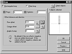
Select Modify, Array. The Array dialog appears (see Figure 6.13). Figure 6.13. The Array dialog box greatly simplifies the ARRAY command.
|
8. |
Verify the new array will be rectangular and then enter 6 for the number of rows. |
9. |
Click the arrow button to the right of the Row Offset edit box. This allows you to pick a distance onscreen for the row distance. The dialog disappears and prompts with Specify the distance between rows:. |
10. |
Activate the Cursor menu (Shift+right-click) and select Intersection. In Figure 6.11, click at |
11. |
Now click the Select Objects button in the top right of the Array dialog. The dialog then disappears and prompts with Select objects:. Select the thread object because it is one single block, and then press Enter. Now click OK. Note The Array dialog does not allow you to click the OK button until you have provided it with enough information to create the array of objects. |
12. |
The array is carried out in a direction perpendicular to the X-axis of the new UCS. |
13. |
Return the UCS to the WCS with the UCS command. Type UCS
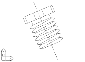
and press Enter at the command prompt. When the following prompt appears, accept the default <World>: . Enter an option [New/Move/orthoGraphic/Prev/Restore/Save/Del/Apply/?/World] <World>: Your drawing should resemble Figure 6.14. Figure 6.14. The completed array.
|
14. |
Leave this drawing open for the following exercise. |
Although defining new UCSs is most frequently used in 3D drafting, the preceding exercise demonstrated that the capability to change the UCS is helpful in 2D work as well. By aligning the UCS with the horizontal axis of the thread object in the drawing, a simple 6-row array could be quickly carried out with the “axis” of the array perpendicular to the horizontal axis of the object. The following exercise demonstrates two more options of the UCS command, reestablishing the most previous UCS and controlling the display of the UCS icon.
Tip
It is possible to change the UCS to the position and orientation you want in more than one way. In the preceding exercise, for example, you could have rotated the UCS about its Z-axis rather than using the 3 Point option. You will generally prefer to use the 3 Point option because it’s more intuitive and easier to use.
Exercise 6.6 Displaying the Previous UCS and Controlling the Position of the UCS Icon
1. | |
2. |
At the command prompt, type UCS
, then press Enter. The following prompt appears: Enter an option [New/Move/orthoGraphic/Prev/Restore/Save/ Del/Apply/?/World] |
3. |
Type P
(for Previous), then press Enter. Note that the UCS reverts to the UCS defined in the previous exercise. |
4. |
Now, select View, Display, UCS Icon, Origin. Note that the UCS icon moves to the origin point of the currently defined UCS as shown in Figure 6.15. This is the origin point you defined in step 4 of the previous exercise. Figure 6.15. Placing the UCS icon at the current origin.
|
5. |
Again, select View, Display, UCS Icon, and notice that a check mark appears beside the Origin selection. Click on Origin to toggle off the feature, which moves the icon back to its former position at the lower-left corner of the screen. |
6. |
Once again, select View, Display, UCS Icon, and notice that a check mark appears beside the On selection. Click On to remove the check mark. Note that the UCS icon is no longer visible. |
7. |
You can close the drawing without saving changes. Tip Although the preceding exercise uses shortcuts from the main menu bar, I prefer to turn the UCS icon on and off by typing UCSICON at the command prompt, and then typing either On or O ff. This method seems faster. You can also move the UCS icon to and from the current origin with the UCSICON command and typing either OR for origin, or N for no origin. This seems faster than traversing across three levels of cascading pull-down menus. |
The UCS Command
The UCS command is the key to placing, moving, rotating, and displaying User Coordinate Systems. This command allows you to appropriately position UCSs to draw the elements necessary to properly define your 2D or 3D model. By understanding the various options available through the UCS command, you ease the task of defining your model.
Most of your 2D work can be accomplished with the following subset of UCS options:
Origin. Specifies a new X-, Y-, or Z-origin point relative to the current origin.
Point. Enables you to set the X- and Y-axes by specifying the origin and a point on both the X and Y axes.
Object. Defines a new coordinate system based on a selected object.
Prev. Reverts to the previous UCS. You can recall as many as the previous 10 UCSs.
Save. Enables you to store the current UCS with a name you specify.
The Restore, Save, Del, and ?/Named UCSs options are tools that allow you to manage UCS configurations. By using these tools, you can save defined UCS configurations, then restore them for later use. One feature that makes these options very useful is that named UCSs are saved with the current drawing. Therefore, as you develop a series of different UCS configurations, you can save the configurations with the drawing, knowing that you can recall them later during another editing session.
Tip
You can use the new AutoCAD DesignCenter (ADC) to import saved UCS configurations from other drawings into the current drawing. For more information, see Chapter 12, “Applications for AutoCAD DesignCenter.”
New UCS Command Features
AutoCAD 2000 introduced several new features to the UCS command. These features enhanced the usefulness of UCSs by making them easier to manipulate. By using these features, you make defining and controlling UCSs simpler.
The features are described as follows:
Multiple UCSs. This feature allows you to set a different UCS for each viewport you have open.
UCS Face Align. This option allows you to quickly configure a new UCS by aligning it to the selected Face object. Face objects are discussed in Chapter 29, “Surfacing in 3D.”
UCS Apply. This option allows you to apply the UCS configuration of one viewport to another by simply selecting the viewport.
UCS Move. This option allows you to move the origin of a UCS without the need to redefine or rename the UCS. For example, if you move the origin point of a named UCS, AutoCAD simply applies the new origin point to the named UCS.
The following exercise demonstrates the new features and options.
Exercise 6.7 AutoCAD’s UCS Features and Options
1. |
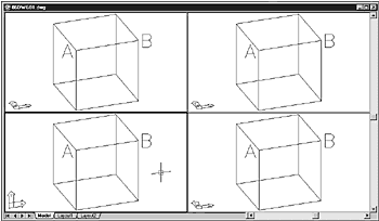
Open the drawing 06DWG02.dwg. The drawing appears, showing four different viewports, all viewing the same cube object, and all having identical UCSs, as shown in Figure 6.16. Figure 6.16. The UCS is identical in each viewport.
|
2. |
Pick anywhere inside the lower-left viewport. The lower-left viewport becomes active. |
3. |
From the Tools menu, select New UCS, Face. AutoCAD prompts you to select the face of a solid object. |
4. |
In the lower-left viewport, pick the line AB, picking near A. AutoCAD highlights the front face of the cube. (If AutoCAD highlights the top face of the cube, choose N to switch to the adjoining face, then press Enter to select to the front face.) |
5. |
Press Enter to accept the front face selection. Notice that AutoCAD rotates the lower-left viewport’s UCS, as shown in Figure 6.17. Also notice that no other UCS rotated in any of the other viewports. Figure 6.17. The UCS Face option aligns the lower-left viewport’s UCS with the selected front face of the cube. Notice that all other UCSs remained unchanged.
|
6. |
From the Tools menu, select New UCS, Apply. AutoCAD prompts you to pick a viewport to apply the current UCS. |
7. |
Choose the upper-right viewport, then press Enter. AutoCAD updates the upper-right viewport’s UCS to match the lower-left viewport’s UCS. |
8. |
From the Tools menu, select Move UCS. AutoCAD prompts you to specify the new origin point for the current UCS. |
9. |
In the upper-right viewport, pick a point in the approximate center of the front face. AutoCAD redefines the UCS’s origin point, and moves the UCS icon to the new origin point. |
10. |
From the Tools menu, select Named UCS. AutoCAD displays the UCS dialog box, with the Named UCSs tab displayed. Notice that the current UCS is Unnamed. |
11. |
Right-click the highlighted Unnamed UCS. AutoCAD displays the shortcut menu. |
12. |
Select Rename, type Front UCS
, and press Enter. AutoCAD renames the UCS, as shown in Figure 6.18. Figure 6.18. The current UCS is renamed Front UCS.
|
13. |
Click OK. AutoCAD dismisses the UCS dialog box. |
14. |
Select the lower-right viewport, then select Tools, Named UCS. AutoCAD displays the UCS dialog box. |
15. |
Select Front UCS, click Set Current, and click OK. AutoCAD redefines the UCS’s origin point, and moves the UCS icon to the new origin point in the current viewport. |
16. |
Select Tools, Named UCS. AutoCAD displays the UCS dialog box. |
17. |
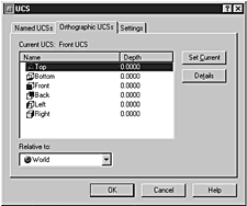
Select the Orthographic UCSs tab. AutoCAD displays six predefined UCSs, as shown in Figure 6.19. Figure 6.19. AutoCAD provides six predefined orthographic UCSs.
|
18. |
Select the orthographic UCS named Left, then Set Current, then click OK. AutoCAD aligns the lower-right viewport’s UCS with the left face of the cube, as shown in Figure 6.20. Figure 6.20. AutoCAD applies the orthographic UCS named Left to the lower-right viewport.
|
19. |
You can close the drawing without saving changes. |
AutoCAD’s UCS features and options make using UCSs easier than before. By applying these tools, you can simplify object editing, and increase your productivity.
The UCSICON Command
In an earlier exercise, you saw how the UCSICON command can be used to control the placement and visibility of the UCS icon. To round out the discussion of User Coordinate Systems, here is an explanation of the options for the UCSICON command. The UCSICON command displays the following prompt:
Enter an option [ON/OFF/All/Noorigin/ORigin] <ON>
All. Applies changes to the UCS icon in all displayed viewports; otherwise, changes affect only the current viewport.
Noorigin. Displays the UCS icon at the lower-left corner of viewports.
Origin. Displays the UCS icon at the 0,0,0 origin of the current UCS if possible. Otherwise, it displays the UCS icon at the lower-left corner of viewports.
Tip
Another capability of the UCS icon that you should know about is the system variable UCSFOLLOW. This variable controls whether or not a plan view will be automatically generated whenever you change the UCS. Setting this variable to 0 will not affect the view; setting it to 1, however, will cause the plan view to be generated. For 2D drafting, I find the automatic plan view setting to be helpful.
The UCS icon options just described can be set from the command prompt, or from the new UCS dialog box. By selecting Tools, Named UCS, then selecting the Settings tab, AutoCAD displays the UCS icon options shown in Figure 6.21. By selecting or clearing the options, you toggle on or off the options, described as follows:
Figure 6.21. The new UCS manager allows you to set options for the UCS icon.

On. When selected, turns on the UCS icon. When cleared, turns off the UCS icon.
Display at UCS Origin Point. When selected, displays the UCS icon at the 0,0,0 origin of the current UCS if possible. When cleared, it displays the UCS icon at the lower-left corner of the viewport.
Apply to All Active Viewports. When selected, applies changes to the UCS icon in all displayed viewports. When cleared, changes to the UCS icon only affect the current viewport.
In addition to the UCS icon settings, you can also control two UCS settings, described as follows:
Save UCS with Viewport. When selected, this option allows you to set and retain a different UCS for each viewport. When cleared, the viewport reflects the current UCS each time the UCS is changed, even if the viewport is not the current viewport.
Update View to Plan When UCS Is Changed. When selected, the plan view is automatically applied when the UCS is changed. When cleared, the plan view is not invoked when the UCS changes. (This is the same as setting the UCSFOLLOW system variable, described in the previous tip.)
The plan view described here refers to rotating the view of the model in the current viewport so that the X axis of the UCS appears normal (horizontal) to the screen. For example, in Figure 6.22, the image on the left has its view rotated normal to the screen, whereas the image on the right does not. You can invoke a plan view by using the PLAN command.
Figure 6.22. The view of the image on the left is automatically rotated by using the PLAN command.


