Chapter 14. BGP High Availability
The following topics are covered in this chapter:
![]() BGP Graceful-Restart
BGP Graceful-Restart
![]() BGP SSO and Nonstop Routing
BGP SSO and Nonstop Routing
![]() BFD
BFD
![]() Fast External Failover
Fast External Failover
![]() Route Dampening
Route Dampening
![]() BGP Add-Path
BGP Add-Path
![]() BGP Prefix-Independent Convergence
BGP Prefix-Independent Convergence
BGP Graceful-Restart
The BGP Graceful-Restart (GR) feature allows a BGP speaker to express its ability to preserve forwarding state during Border Gateway Protocol (BGP) restart or Route Processor (RP) switchover. In other words, it is the capability exchanged between the BGP speakers to indicate its ability to perform Nonstop Forwarding (NSF). This helps in minimizing the impact of services caused by BGP restart. Specially in large network deployments, where BGP carries large number of prefixes, a BGP restart, especially by a route-reflector (RR) router, can have a severe performance and service impact and can lead to major outages.
Examine the network topology shown in Figure 14-1. R1 is acting as the RR and its peering with multiple clients. If there is a BGP restart or RP switchover on R1, the peer detects the session flaps and propagate routing updates throughout the network. This can lead to increased CPU utilization if the RR is holding a large BGP table. The traffic destined to the prefixes that were removed are impacted.

RFC 4724 defines the GR mechanism for BGP. The BGP GR was developed with the following motivations:
![]() Avoid widespread routing changes.
Avoid widespread routing changes.
![]() Decrease control plane overhead throughout the network.
Decrease control plane overhead throughout the network.
![]() Enhance overall stability of routing.
Enhance overall stability of routing.
A GR-capable device announces its ability to perform GR for the BGP peer. It also initiates the graceful-restart process when a RP switchover occurs and acts as a GR-aware device. A GR-aware device, also known GR helper mode, is capable of understanding that a peer router is transitioning and takes appropriate actions based on the configuration or default timers.
GR capability should always be enabled for all routing protocols, especially when the routers are running with dual route processors (RP) and perform a switchover in case of any failure instance. Because BGP runs on Transmission Control Protocol (TCP), GR should be enabled on both the peering devices. After GR is configured or enabled on both peering devices, reset the BGP session to exchange the capability and activate the GR feature.
Note
GR is always on by default for non-TCP–based protocols such as Interior Gateway Protocol (IGPs). These protocols start operating in GR mode as soon as the other side is configured with GR capability.
BGP GR is an optional feature and is not enabled by default. BGP peers announce GR capability in the BGP OPEN message. Within the OPEN message, the following information is negotiated:
![]() Restart Flag: This bit indicates if a peer sending the GR capability has just restarted. This is used to prevent deadlocks if both peers restart at the same time.
Restart Flag: This bit indicates if a peer sending the GR capability has just restarted. This is used to prevent deadlocks if both peers restart at the same time.
![]() Restart Time: Indicates the length of time that the sender of the GR capability requires to complete a restart. The restart timer also helps in speeding up convergence in the event the peer never comes back up after a restart.
Restart Time: Indicates the length of time that the sender of the GR capability requires to complete a restart. The restart timer also helps in speeding up convergence in the event the peer never comes back up after a restart.
![]() Address-Family Identifier (AFI)/Subaddress-Family Identifier (SAFI): Address-family for which GR is supported.
Address-Family Identifier (AFI)/Subaddress-Family Identifier (SAFI): Address-family for which GR is supported.
![]() AFI Flags: It contains a Forwarding State bit. This bit indicates whether the peer sending the GR capability has preserved forwarding during the previous restart.
AFI Flags: It contains a Forwarding State bit. This bit indicates whether the peer sending the GR capability has preserved forwarding during the previous restart.
Peers can include GR capability without including any address-families. This implies GR awareness (nonrestarting support for GR) without the ability to perform a GR.
When a BGP restart happens on the peer router or when RP switchover occurs, the routes currently held in the forwarding table; that is, hardware, are marked as stable. This way, the forwarding state is preserved as the control plane and the forwarding plane operate independently. On the restarting peer (where the switchover occurred), BGP on the newly active RP starts to establish sessions with all the configured peers. BGP on the other side, the nonrestarting side, sees new connection requests coming in while BGP already is in established state. Such an event is an indication for the nonrestarting peer that the peer has restarted. At this point, the restarting peer sends the GR capability with Restart State bit set to 1 and Forwarding State bit set to 1 for the AFI/SAFIs.
The nonrestarting peer at this point cleans up old (dead) BGP sessions and marks all the routes in the BGP table that are received from the restarting peer as stale. If the restarting peer never reestablishes the BGP session, the nonrestarting peer purges all stale routes after the Restart Time expires. The nonrestarting peer sends an initial routing table update, followed by an End-of-RIB (EoR) marker. Restarting peer delays best-path calculation for an AFI until after receiving EoR from all peers except for those that are not GR capable or for the ones that have Restart State bit set.
The restarting peer finally generates updates for its peers and sends the EoR marker for each AFI after the initial table is sent. The nonrestarting peers receive the routing updates from the restarting peer and remove stale marking for any refreshed route. It purges any remaining stale routes after EoR is received from the restarting peer or the Stale Path Timer expires.
GR can be configured both globally or on a per neighbor basis. Use the command bgp graceful-restart to enable GR globally. Example 14-1 demonstrates the global configuration of GR on Cisco IOS, IOS XR, and NX-OS platforms. Use the command bgp graceful-restart restart-time value to set the GR restart timer and the command bgp graceful-restart stalepath-time value to set the maximum time for which the router will maintain the stale path entries in case it does not receives an EoR from the restarting peer. In IOS XR, the command bgp graceful-restart stalepath-timer sets the maximum time to wait for restart of GR capable peers and a new command is introduced to take care of purging the stale paths from the peer—bgp graceful-restart purge-time value.
Example 14-1 Global Configuration for Graceful-Restart
! Configuration on Cisco IOS
R1(config)# router bgp 100
R1(config-router)# bgp graceful-restart
R1(config-router)# bgp graceful-restart restart-time 300
R1(config-router)# bgp graceful-restart stalepath-time 400
! Configuration on IOS XR
RP/0/0/CPU0:R2(config-line)# router bgp 100
RP/0/0/CPU0:R2(config-bgp)# bgp graceful-restart
RP/0/0/CPU0:R2(config-bgp)# bgp graceful-restart restart-time 300
RP/0/0/CPU0:R2(config-bgp)# bgp graceful-restart stalepath-time 400
RP/0/0/CPU0:R2(config-bgp)# bgp graceful-restart purge-time 400
RP/0/0/CPU0:R2(config-bgp)# commit
! Configuration on NX-OS
R3(config)# router bgp 100
R3(config-router)# graceful-restart
R3(config-router)# graceful-restart restart-time 300
R3(config-router)# graceful-restart stalepath-time 400
If the BGP session is already in established state before GR configuration, the BGP sessions are required to be reset in order to exchange the GR capability. The GR capability is verified by using the command show bgp afi safi neighbors ip-address. Examine the output of show bgp ipv4 unicast neighbors ip-address in Example 14-2. Notice that in the command output, the GR capability is in advertised and received state. If either the advertised or received state is missing, it means that one of the peers is not having GR configured or the GR was configured after the session came up.
Example 14-2 Verifying GR Capability for BGP Neighbor
! Command Output on Cisco IOS
R1# show bgp ipv4 unicast neighbors 192.168.2.2
BGP neighbor is 192.168.2.2, remote AS 100, internal link
BGP version 4, remote router ID 192.168.2.2
BGP state = Established, up for 01:10:35
Last read 00:00:30, last write 00:00:29, hold time is 180, keepalive interval is
60 seconds
Neighbor sessions:
1 active, is not multisession capable (disabled)
Neighbor capabilities:
Route refresh: advertised and received(new)
Four-octets ASN Capability: advertised and received
Address family IPv4 Unicast: advertised and received
Graceful Restart Capability: advertised and received
Remote Restart timer is 300 seconds
Address families advertised by peer:
IPv4 Unicast (was not preserved
Enhanced Refresh Capability: advertised
! Output omitted for brevity
! Command Output on IOS XR
RP/0/0/CPU0:R2# show bgp ipv4 unicast neighbors 192.168.1.1
BGP neighbor is 192.168.1.1
Remote AS 100, local AS 100, internal link
Remote router ID 192.168.1.1
Cluster ID 192.168.2.2
BGP state = Established, up for 01:11:37
NSR State: None
Last read 00:00:41, Last read before reset 01:11:39
Hold time is 180, keepalive interval is 60 seconds
Configured hold time: 180, keepalive: 60, min acceptable hold time: 3
Last write 00:00:31, attempted 19, written 19
Second last write 00:01:31, attempted 19, written 19
Last write before reset 01:11:39, attempted 82, written 82
Second last write before reset 01:11:46, attempted 19, written 19
Last write pulse rcvd May 12 05:12:40.534 last full not set pulse count 267
Last write pulse rcvd before reset 01:11:39
Socket not armed for io, armed for read, armed for write
Last write thread event before reset 01:11:39, second last 01:11:39
Last KA expiry before reset 00:00:00, second last 00:00:00
Last KA error before reset 00:00:00, KA not sent 00:00:00
Last KA start before reset 00:00:00, second last 00:00:00
Precedence: internet
Non-stop routing is enabled
Graceful restart is enabled
Restart time is 300 seconds
Stale path timeout time is 400 seconds
Multi-protocol capability received
Neighbor capabilities:
Route refresh: advertised (old + new) and received (old + new)
Graceful Restart (GR Awareness): received
4-byte AS: advertised and received
Address family IPv4 Unicast: advertised and received
Received 140 messages, 1 notifications, 0 in queue
Sent 126 messages, 1 notifications, 0 in queue
Minimum time between advertisement runs is 0 secs
Inbound message logging enabled, 3 messages buffered
Outbound message logging enabled, 3 messages buffered
For Address Family: IPv4 Unicast
BGP neighbor version 2
Update group: 0.3 Filter-group: 0.4 No Refresh request being processed
Route-Reflector Client
AF-dependent capabilities:
Graceful Restart capability advertised
Local restart time is 300, RIB purge time is 400 seconds
Maximum stalepath time is 400 seconds
! Output omitted for brevity
! Command Output on NX-OS
R3# show bgp ipv4 unicast neighbors 192.168.2.2
BGP neighbor is 192.168.2.2, remote AS 100, ibgp link, Peer index 1
BGP version 4, remote router ID 192.168.2.2
BGP state = Established, up for 02:03:32
Using loopback0 as update source for this peer
Last read 00:00:22, hold time = 180, keepalive interval is 60 seconds
Last written 00:00:29, keepalive timer expiry due 00:00:30
Received 172 messages, 1 notifications, 0 bytes in queue
Sent 173 messages, 0 notifications, 0 bytes in queue
Connections established 2, dropped 1
Last reset by peer 02:03:43, due to session cleared
Last reset by us never, due to No error
Neighbor capabilities:
Dynamic capability: advertised (mp, refresh, gr)
Dynamic capability (old): advertised
Route refresh capability (new): advertised received
Route refresh capability (old): advertised received
4-Byte AS capability: advertised received
Address family IPv4 Unicast: advertised received
Graceful Restart capability: advertised received
Graceful Restart Parameters:
Address families advertised to peer:
IPv4 Unicast
Address families received from peer:
IPv4 Unicast
Forwarding state preserved by peer for:
Restart time advertised to peer: 300 seconds
Stale time for routes advertised by peer: 400 seconds
Restart time advertised by peer: 300 seconds
! Output omitted for brevity
Sometimes, not all peers are GR capable and are not required to be GR capable as well. GR can also be configured on a per-neighbor basis and having the GR globally disabled. This helps in exchanging GR capability with only those neighbors for which forwarding should not be impacted or be least impacted. GR is enabled for an individual neighbor using the command neighbor ip-address graceful-restart on both Cisco IOS XR and NX-OS and using the command neighbor ip-address ha-mode graceful-restart on Cisco IOS software. Example 14-3 demonstrates the configuration of GR on a per-neighbor basis.
Example 14-3 Per-Neighbor Graceful-Restart Configuration
! Configuration on Cisco IOS
R1(config)# router bgp 100
R1(config-router)# neighbor 192.168.2.2 ha-mode graceful-restart
! Configuration on IOS XR
RP/0/0/CPU0:R2(config)# router bgp 100
RP/0/0/CPU0:R2(config-bgp)# neighbor 192.168.1.1
RP/0/0/CPU0:R2(config-bgp-nbr)# graceful-restart
! Configuration on NX-OS
R3(config)# router bgp 100
R3(config-router)# neighbor 192.168.2.2
R3(config-router-neighbor)# graceful-restart
The NX-OS software also supports for GR-aware feature configuration; that is, the router does not perform full GR functionality but can have peers that are GR capable and is capable of sending EoR to restarting peers. This feature can also be configured on NX-OS either globally or on a per-neighbor basis. To enable GR aware configuration, use the global BGP command graceful-restart-helper or use the neighbor command neighbor ip-address graceful-restart-helper.
Cisco’s implementation of GR assumes NSF is enabled and tells the peers: “If I ever drop this session, it is because I am failing over from primary RP to secondary RP and will keep forwarding packets.” This makes the peer think that it needs to keep sending the packets. This scenario works as long as there is no reload or reboot on the router. If the router goes down, the neighbor router keeps sending the packets to this router, instead of forwarding the traffic to a working path, assuming the router that restarted is performing a switchover and it has its Forwarding Information Base (FIB) updated. This causes the traffic to black hole and causes an outage.
The problem is not with the feature itself but with the understanding between GR and NSF. GR does not mean that NSF is enabled but only assumes that NSF is enabled on the router. NSF is not configurable but is enabled by default when the router is running in Stateful Switchover (SSO) mode. NSF can also be defined as a function to checkpoint the FIB on the standby router.
The GR Restart Timer, which defaults to 120 seconds, takes care of clearing the stale path entries in case the BGP peer does not comes up within this time period.
Note
Before moving to the next topic, it is important to understand routers’ and switches’ different high-availability operating modes with dual RPs.
![]() Stateful Switchover (SSO): Failover from the active RP (crashing or reloading) to the standby RP (which takes over as the active role) where state is preserved and the router was in hot-standby mode before the switchover.
Stateful Switchover (SSO): Failover from the active RP (crashing or reloading) to the standby RP (which takes over as the active role) where state is preserved and the router was in hot-standby mode before the switchover.
![]() RPR+: RP redundancy mode where standby RP is partially initialized, but there is no synchronization of state.
RPR+: RP redundancy mode where standby RP is partially initialized, but there is no synchronization of state.
It is required to have SSO state for features like NSF, Nonstop Routing (NSR), or GR.
BGP Nonstop Routing
High-availability features like GR are really useful in critical network environments, where traffic loss even for few seconds can cost a lot to the organization, whether it is a service provider network or an enterprise. But GR is not really a feasible solution in all deployments. Think about a service provider network. It is easy to deploy a GR feature everywhere in the service provider core and edge, but the service provider cannot expect to have the customers enable GR or be GR capable. There might be customer environments where the customer premises equipment (CPE) might be running a platform or software that does not support GR or might be running the CPE with just a single RP. In such situations, GR is not feasible for the customers.
An RP switchover should be transparent to the customer, and this was the primary motivation behind NSR. NSR is a feature where routing protocols explicitly checkpoint state from active RP to the standby RP to maintain routing information across a switchover. Thus, NSR sessions are in established state on the standby RP prior to switchover and remain established even after the switchover. The main benefit of using NSR is it is transparent to the remote speaker; that is, the remote does not need to be NSR capable for the feature to work.
There are three phases in NSR operation. Each phase performs certain actions, and based on these phases, it becomes easier to identify any problem with BGP NSR.
![]() Synchronization: During this state, the task of session state mirroring happens between the active and the standby RP. The TCP stack is first synchronized, followed by the application stacks—in this case, BGP.
Synchronization: During this state, the task of session state mirroring happens between the active and the standby RP. The TCP stack is first synchronized, followed by the application stacks—in this case, BGP.
![]() NSR-ready: The active and standby stacks operate independently, but the incoming packets or updates are replicated to both the RPs. The outgoing segments or updates are sent out via the standby RP or active RP depending on the underlying platform. On IOS/IOS XE, the active RP sends the update to the peers, but on IOS XR, the update is sent out via the standby RP. Note that the system uses asynchronous inter-process communication (IPC) between the active and standby RPs to replicate the information. In this state, the active RP sends prefix/best-path information to the standby.
NSR-ready: The active and standby stacks operate independently, but the incoming packets or updates are replicated to both the RPs. The outgoing segments or updates are sent out via the standby RP or active RP depending on the underlying platform. On IOS/IOS XE, the active RP sends the update to the peers, but on IOS XR, the update is sent out via the standby RP. Note that the system uses asynchronous inter-process communication (IPC) between the active and standby RPs to replicate the information. In this state, the active RP sends prefix/best-path information to the standby.
![]() Switchover: When the switchover occurs, TCP activates the sockets based on the application trigger and restores keepalive functionality to maintain the session states. In other words, the new active RP (previously acting standby RP) continues from where the active RP left.
Switchover: When the switchover occurs, TCP activates the sockets based on the application trigger and restores keepalive functionality to maintain the session states. In other words, the new active RP (previously acting standby RP) continues from where the active RP left.
Figure 14-2 depicts the BGP NSR architecture with the various functions occurring between the active and the standby RP on Cisco IOS/IOS XE platform.

The BGP NSR feature is supported on IOS/IOS XE and IOS XR platforms. To enable BGP NSR on Cisco IOS, use the command neighbor ip-address ha-mode sso. On IOS XR, NSR is not supported on a per-neighbor basis and can only be enabled globally for all address families using the command nsr under the router bgp configuration mode. Example 14-4 demonstrates the configurations of BGP NSR on both Cisco IOS and IOS XR platforms. NSR is enabled globally on Cisco IOS by using the command bgp sso route-refresh-enable. This command only allows BGP NSR to be enabled to peers that are Route Refresh capable.
Example 14-4 BGP NSR Configuration
! Configuration on Cisco IOS
R1(config)# router bgp 100
R1(config-router)# bgp sso route-refresh-enable
R1(config-router)# neighbor 192.168.2.2 ha-mode sso
! Configuration on IOS XR
RP/0/0/CPU0:R2(config)# router bgp 100
RP/0/0/CPU0:R2(config-bgp)# nsr
RP/0/0/CPU0:R2(config-bgp)# commit
The BGP NSR related information is found for each peer by using the command show bgp afi safi neighbor ip-address. Example 14-5 displays the output of the command show bgp ipv4 unicast neighbors ip-address to verify the BGP NSR status. On IOS XR, another command to verify if NSR is enabled for the BGP process is the command show bgp process. This command displays the information related to the BGP process, such as Router ID, default timers, NSR information, and other generic information.
Example 14-5 BGP NSR Verification
IOS
R1# show bgp ipv4 unicast neighbors 192.168.2.2
BGP neighbor is 192.168.2.2, remote AS 100, internal link
BGP version 4, remote router ID 192.168.2.2
BGP state = Established, up for 08:13:01
Last read 00:00:00, last write 00:00:11, hold time is 180, keepalive interval is
60 seconds
Neighbor sessions:
1 active, is not multisession capable (disabled)
Neighbor capabilities:
Route refresh: advertised and received(new)
Four-octets ASN Capability: advertised and received
Address family IPv4 Unicast: advertised and received
Enhanced Refresh Capability: advertised
Multisession Capability:
Stateful switchover support enabled: NO for session 1
! Output omitted for brevity
IOS XR
RP/0/0/CPU0:R2# show bgp ipv4 unicast neighbors 192.168.1.1
BGP neighbor is 192.168.1.1
Remote AS 100, local AS 100, internal link
Remote router ID 192.168.1.1
Cluster ID 192.168.2.2
BGP state = Established, up for 08:26:48
NSR State: None
Last read 00:00:37, Last read before reset 00:00:00
Hold time is 180, keepalive interval is 60 seconds
Configured hold time: 180, keepalive: 60, min acceptable hold time: 3
Last write 00:00:40, attempted 19, written 19
Second last write 00:01:40, attempted 19, written 19
Last write before reset 00:00:00, attempted 0, written 0
Second last write before reset 00:00:00, attempted 0, written 0
Last write pulse rcvd May 15 11:52:27.695 last full not set pulse count 1074
Last write pulse rcvd before reset 00:00:00
Socket not armed for io, armed for read, armed for write
Last write thread event before reset 00:00:00, second last 00:00:00
Last KA expiry before reset 00:00:00, second last 00:00:00
Last KA error before reset 00:00:00, KA not sent 00:00:00
Last KA start before reset 00:00:00, second last 00:00:00
Precedence: internet
Non-stop routing is enabled
Multi-protocol capability received
Neighbor capabilities:
Route refresh: advertised (old + new) and received (old + new)
! Output omitted for brevity
RP/0/0/CPU0:R2# show bgp process
BGP Process Information:
BGP is operating in STANDALONE mode
Autonomous System number format: ASPLAIN
Autonomous System: 100
Router ID: 192.168.2.2 (manually configured)
Default Cluster ID: 192.168.2.2
Active Cluster IDs: 192.168.2.2
Fast external fallover enabled
Neighbor logging is enabled
Enforce first AS enabled
Default local preference: 100
Default keepalive: 60
Non-stop routing is enabled
Update delay: 120
Generic scan interval: 60
Address family: IPv4 Unicast
Dampening is not enabled
! Output omitted for brevity
In IOS XR, there are instances when a process crashes because of various reasons. So, if a TCP or BGP process starts on the active RP, the system can force the active RP to failover to standby RP as a recovery action in such situations. But this is not done automatically. To enable this behavior, configure the command nsr process-failures switchover. Note that if a process restarts on the standby RP, only the NSR functionality is lost until the time the process comes up again, but there is not any other service impact.
From the command-line perspective, there isn’t much information that can be viewed on the Cisco IOS or IOS XE platforms, but on IOS XR, a lot of information is available for BGP NSR. The BGP NSR goes through various states. Figure 14-3 examines the finite state machine (FSM) that BGP NSR goes through at different stages.

The following describes the different states of the BGP NSR finite state machine:
![]() None: NSR is disabled (not configured).
None: NSR is disabled (not configured).
![]() Initializing: Basic initialization in progress. This is done after the first time NSR is configured.
Initializing: Basic initialization in progress. This is done after the first time NSR is configured.
![]() Connecting: Attempting to connect to peer (ACTV/STDBY) process.
Connecting: Attempting to connect to peer (ACTV/STDBY) process.
![]() TCP Init-Sync: Synchronization of TCP sessions in progress.
TCP Init-Sync: Synchronization of TCP sessions in progress.
![]() BGP Init-Sync: Synchronization of BGP database in progress.
BGP Init-Sync: Synchronization of BGP database in progress.
![]() NSR-Ready: Ready to perform NSR-enabled switchover.
NSR-Ready: Ready to perform NSR-enabled switchover.
Note that in Example 14-5, the NSR state is None. This is because there is not a standby RP present in the system. In an ideal situation with dual RPs, the NSR state should be NSR-Ready. To view the NSR state on a dual RP system, use the command show redundancy. This command displays the active and the standby RP redundancy states.
Example 14-6 displays the output of the command show redundancy from another node running on dual RPs. Also the command show bgp ipv4 unicast neighbor ip-address command displays the NSR state as NSR-Ready.
Example 14-6 Redundancy Status
RP/0/RSP0/CPU0:R2# show redundancy
Redundancy information for node 0/RSP0/CPU0:
==========================================
Node 0/RSP0/CPU0 is in ACTIVE role
Node Redundancy Partner (0/RSP0/CPU0) is in STANDBY role
Standby node in 0/RSP1/CPU0 is ready
Standby node in 0/RSP1/CPU0 is NSR-ready
Node 0/RSP0/CPU0 is in process group PRIMARY role
Process Redundancy Partner (0/RSP1/CPU0) is in BACKUP role
Backup node in 0/RSP1/CPU0 is ready
Backup node in 0/RSP1/CPU0 is NSR-ready
Group Primary Backup Status
--------- --------- --------- ---------
dsc 0/RSP0/CPU0 0/RSP1/CPU0 Ready
dlrsc 0/RSP0/CPU0 0/RSP1/CPU0 Ready
central-services 0/RSP0/CPU0 0/RSP1/CPU0 Ready
v4-routing 0/RSP0/CPU0 0/RSP1/CPU0 Ready
netmgmt 0/RSP0/CPU0 0/RSP1/CPU0 Ready
mcast-routing 0/RSP0/CPU0 0/RSP1/CPU0 Ready
v6-routing 0/RSP0/CPU0 0/RSP1/CPU0 Ready
Group_10_bgp2 0/RSP0/CPU0 0/RSP1/CPU0 Ready
Group_5_bgp3 0/RSP0/CPU0 0/RSP1/CPU0 Ready
RP/0/RSP0/CPU0:R2# show bgp ipv4 unicast neighbors 192.168.1.1
BGP neighbor is 192.168.1.1
Remote AS 100, local AS 100, internal link
Remote router ID 192.168.1.1
Speaker ID 1
BGP state = Established, up for 1d04h
NSR State: NSR Ready
Last read 00:00:03, Last read before reset 1d04h
! Output omitted for brevity
Use the command show bgp afi safi [prefix | summary] [standby] to view the BGP session state and the BGP table for an AFI/SAFI on the standby RP.
Note
If a manual switchover is required for maintenance purposes, ensure that the redundancy state is Standby hot and also the standby is in NSR-Ready state. This ensures seamless activity without any service impact.
After a switchover, the standby RP goes through all the NSR states as previously mentioned. This information is viewed by using the command show bgp summary nsr or show bgp nsr. These commands display all the various modes that the standby goes through after it moves to a standby ready state along with the timeline. It also shows the state of the BGP neighbor along with the NSR state. To view the NSR states and the neighbor state on the standby RP, use the command show bgp summary nsr standby. Example 14-7 displays the command output of the show bgp summary nsr command.
Example 14-7 show bgp summary nsr Command Output
RP/0/RSP0/CPU0:R2# show bgp summary nsr
BGP router identifier 192.168.2.2, local AS number 100
BGP generic scan interval 60 secs
Non-stop routing is enabled
BGP table state: Active
Table ID: 0xe0000000 RD version: 37
BGP main routing table version 37
BGP NSR Initial initsync version 3 (Reached)
BGP scan interval 60 secs
BGP is operating in STANDALONE mode.
node0_RSP0_CPU0 Speaker
Entered mode Standby Ready : May 15 15:35:05
Entered mode TCP NSR Setup : May 15 15:35:05
Entered mode TCP NSR Setup Done : May 15 15:35:05
Entered mode TCP Initial Sync : May 15 15:35:05
Entered mode TCP Initial Sync Phase Two : May 15 15:35:06
Entered mode TCP Initial Sync Done : May 15 15:35:07
Entered mode FPBSN processing done : May 15 15:35:07
Entered mode Update processing done : May 15 15:35:07
Entered mode BGP Initial Sync : May 15 15:35:07
Entered mode BGP Initial Sync done : May 15 15:35:07
Entered mode NSR Ready : May 15 15:35:07
Current BGP NSR state - NSR Ready achieved at: May 15 15:35:07
NSR State READY notified to Rmf at: May 15 15:35:07
Process RcvTblVer bRIB/RIB LabelVer ImportVer SendTblVer StandbyVer
Speaker 37 37 37 37 37 37
Neighbor Spk AS TblVer SyncVer AckVer NBRState NSRState
192.168.1.1 1 100 37 37 37 Established NSR Ready
RP/0/RSP0/CPU0:R2# show bgp summary nsr standby
Mon May 16 06:44:38.868 UTC
BGP router identifier 192.168.2.2, local AS number 100
BGP generic scan interval 60 secs
Non-stop routing is enabled
BGP table state: Active
Table ID: 0xe0000000 RD version: 37
BGP main routing table version 37
BGP NSR Initial initsync version 1 (Not Reached)
BGP tunnel nexthop version 1
BGP scan interval 60 secs
BGP is operating in STANDALONE mode.
node0_RSP1_CPU0 Speaker
Entered mode None : May 15 15:34:05
Entered mode Standby Ready : May 15 15:35:05
Entered mode TCP Replication : May 15 15:35:05
Entered mode TCP Init Sync Done : May 15 15:35:07
Entered mode NSR Ready : May 15 15:35:07
Process RcvTblVer bRIB/RIB LabelVer ImportVer SendTblVer StandbyVer
Speaker 37 1 37 37 1 0
Neighbor Spk AS TblVer SyncVer AckVer NBRState NSRState
192.168.1.1 1 100 37 0 1 Established NSR Ready
A cumulative view of all the session states, that is, Neighbor State and NSR State, is viewed by using the command show bgp sessions. If there are sessions that are not NSR ready, such sessions are viewed by using the command show bgp sessions [not-nsr-ready]. Example 14-8 displays the BGP sessions that are not NSR ready. The output indicates the NSRState field as None because it was captured when the IOS XR router R2 was running on single RP.
Example 14-8 Not-NSR-Ready BGP Sessions
RP/0/RSP0/CPU0:R2# show bgp sessions not-nsr-ready
Neighbor VRF Spk AS InQ OutQ NBRState NSRState
192.168.1.1 default 0 100 0 0 Established None
Because the TCP state is required to be synchronized between the active RP and the standby RP, it is vital to verify how many sessions an application (in this case BGP) ask TCP to synchronize and how many have actually synchronized. To verify this information, use the command show tcp nsr session-set brief. Examine the output of this command in Example 14-9. The IPv4 AFI has total of one session to sync, and the output shows that it has been synced on the standby.
Example 14-9 TCP NSR Sync Information
RP/0/RSP0/CPU0:R2# show tcp nsr session-set brief
--------------------------------------------------------------
Node: 0/RSP0/CPU0
--------------------------------------------------------------
SSCB Client LocalAPP Set-Id Family State Protect-Node Total/Synced
0x10272978 581993 bgp#1 1 IPv4 Ac YN 0/RSP1/CPU0 1/1
0x1017f338 581993 bgp#1 2 IPv6 Ac YN 0/RSP1/CPU0 0/0
While troubleshooting BGP NSR issues, ensure that the TCP session related to BGP is synched with the standby or is NSR ready. This is verified by using the command show tcp nsr brief. In this command, look for the same protocol control block (PCB) value that is achieved from the command show tcp brief and ensure that the NSR state is Up. Example 14-10 illustrates how to verify if the TCP session is NSR ready.
Example 14-10 Verifying TCP NSR State
RP/0/0/CPU0:R2# show tcp brief
PCB VRF-ID Recv-Q Send-Q Local Address Foreign Address State
0x10161660 0x60000000 0 0 192.168.2.2:646 192.168.10.1:25070 ESTAB
0x101698b0 0x60000000 0 0 192.168.2.2:646 192.168.3.3:23158 ESTAB
0x102311b4 0x60000000 0 0 192.168.2.2:179 192.168.1.1:41318 ESTAB
RP/0/RSP0/CPU0:R2# show tcp nsr brief
Tue May 17 05:18:15.908 UTC
--------------------------------------------------------------
Node: 0/RSP0/CPU0
--------------------------------------------------------------
PCB VRF-ID Local Address Foreign Address NSR
0x102311b4 0x60000000 192.168.2.2:179 192.168.1.1:41318 Up
The command show tcp nsr detail pcb pcb-value displays how much time was taken to perform the initial sync for the TCP connection. Example 14-11 shows the output of the command show tcp nsr detail pcb pcb-value of the previously stated TCP connection.
Example 14-11 TCP NSR Session Detail
RP/0/RSP0/CPU0:R2# show tcp nsr detail pcb 0x102311b4
Tue May 17 05:22:34.573 UTC
--------------------------------------------------------------
Node: 0/RSP0/CPU0
--------------------------------------------------------------
==============================================================
PCB 0x102311b4, VRF Id 0x60000000, Client PID: 56177002
Local host: 192.168.2.2, Local port: 179
Foreign host: 192.168.1.1, Foreign port: 41318
SSCB 0x102316d4, Client PID 56177002
Node Role: Active, Protected by: 0/RSP1/CPU0, Cookie: 0x00000000
NSR State: Up
Replicated to standby: Yes
Synchronized with standby: Yes
FSSN: 1823391429, FSSN Offset: 0
ID of the last or current initial sync: 2077858654
Initial sync done in two phases: yes
Initial sync started at: Sun May 15 15:35:05 2016
Initial sync ended at: Sun May 15 15:35:07 2016
Number of incoming packets currently held: 0
Number of iACKS currently held: 0
If there is a delay noticed between the sync, the TCP packet can be traced within the system to examine what action is being taken for a particular packet along with the packet details, such as sequence number, ack, length, window size, and so on. Use the command show tcp packet-trace pcb-value to trace the TCP packet. Example 14-12 examines the packet for the TCP session established by the BGP session between 192.168.2.2 and 192.168.1.1.
Example 14-12 TCP Packet Trace
RP/0/RSP0/CPU0:R2# show tcp packet-trace 0x102311b4
==============================================================
Packet traces for: PCB 0x102311b4, 192.168.2.2:179 <-> 192.168.1.1:41318,
VRF 0x60000000
May 17 04:56:58.757>S (app write)
snduna 3633157372 sndnxt 3633157372 sndmax 3633157372 sndwnd 32198
rcvnxt 1823434377 rcvadv 1823466820 rcvwnd 32443
May 17 04:56:58.757>s --A-P- SEQ 3633157372 ACK 1823434377 LEN 19 WIN 47998 (pak:
0x0, line: 733)
snduna 3633157372 sndnxt 3633157391 sndmax 3633157391 sndwnd 32198
rcvnxt 1823434377 rcvadv 1823466820 rcvwnd 32443
May 17 04:56:58.960>R --A--- SEQ 1823434377 ACK 3633157391 LEN 0 WIN 32179 (pak:
0xb196c50b, line: 3603)
snduna 3633157372 sndnxt 3633157391 sndmax 3633157391 sndwnd 32198
rcvnxt 1823434377 rcvadv 1823466820 rcvwnd 32443
May 17 04:56:58.960>D --A--- SEQ 1823434377 ACK 3633157391 LEN 0 WIN 32179 (pak:
0xb196c50b, line: 893)
snduna 3633157391 sndnxt 3633157391 sndmax 3633157391 sndwnd 32179
rcvnxt 1823434377 rcvadv 1823466820 rcvwnd 32443
May 17 04:57:47.569>R --A-P- SEQ 1823434377 ACK 3633157391 LEN 19 WIN 32179 (pak:
0xb1971453, line: 3603)
snduna 3633157391 sndnxt 3633157391 sndmax 3633157391 sndwnd 32179
rcvnxt 1823434377 rcvadv 1823466820 rcvwnd 32443
May 17 04:57:47.569>R (app read)
snduna 3633157391 sndnxt 3633157391 sndmax 3633157391 sndwnd 32179
rcvnxt 1823434396 rcvadv 1823466820 rcvwnd 32424
! Output omitted for brevity
If the TCP data related to TCP packet flow, the socket state for session that is already closed, and so on is required for investigating what happened to the TCP session, use the command show tcp dump-file filename. The filename for the peer is found using the command show tcp dump-file list ip-address.
The show bgp trace sync command is also very useful to view the timelines of various state changes. This command is useful if there is a delay in the BGP NSR sync. Example 14-13 displays the output of the command show bgp trace sync [reverse]. The reverse keyword is used to view the output in reversed form so that you don’t have to scroll down to the end to view the latest logs. The unfiltered command gives more details on what is happening during the sync process, but filtering the output for just NSR state can help identify where the actual delay occurred, and further logs can be reviewed around the same timeline.
RP/0/RSP0/CPU0:R2# show bgp trace sync reverse | inc "NSR state"
15:35:07.737 default-bgp/spkr-tr2-sync 0/RSP0/CPU0 t16 [SYNC]:4831: Active
NSR state trans, event 'Stdby NSR ack', state 'BGP Initial Sync done'
-> 'NSR Ready'
15:35:07.734 default-bgp/spkr-tr2-sync 0/RSP0/CPU0 t16 [SYNC]:4831: Active
NSR state trans, event 'BGP Initial sync done', state 'BGP Initial Sync'
-> 'BGP Initial Sync done'
15:35:07.733 default-bgp/spkr-tr2-sync 0/RSP0/CPU0 t16 [SYNC]:4831: Active
NSR state trans, event 'Standby ready for BGP sync message', state
'Update processing done' -> 'BGP Initial Sync'
15:35:07.732 default-bgp/spkr-tr2-sync 0/RSP0/CPU0 t16 [SYNC]:4831: Active NSR state
trans, event 'Update Processing Done', state 'FPBSN processing done' -> 'Update
processing done'
15:35:07.732 default-bgp/spkr-tr2-sync 0/RSP0/CPU0 t16 [SYNC]:4831: Active
NSR state trans, event 'FPBSN Processing done', state 'TCP Initial Sync Done'
-> 'FPBSN processing done'
15:35:07.732 default-bgp/spkr-tr2-sync 0/RSP0/CPU0 t16 [SYNC]:4831: Active
NSR state trans, event 'TCP initial sync done', state 'TCP Initial Sync' ->
'TCP Initial Sync Done'
15:35:05.725 default-bgp/spkr-tr2-sync 0/RSP0/CPU0 t16 [SYNC]:4831: Active
NSR state trans, event 'End of Convergence', state 'TCP NSR Setup Done' ->
'TCP Initial Sync'
15:35:05.725 default-bgp/spkr-tr2-sync 0/RSP0/CPU0 t16 [SYNC]:4831: Active
NSR state trans, event 'TCP NSR setup done', state 'TCP NSR Setup' ->
'TCP NSR Setup Done'
15:35:05.724 default-bgp/spkr-tr2-sync 0/RSP0/CPU0 t16 [SYNC]:4831: Active
NSR state trans, event 'End of read-only', state 'Standby Ready' ->
'TCP NSR Setup'
15:35:05.724 default-bgp/spkr-tr2-sync 0/RSP0/CPU0 t16 [SYNC]:4831: Active
NSR state trans, event 'Standby ready message', state 'None' ->
'Standby Ready'
15:34:04.258 default-bgp/spkr-tr2-sync 0/RSP0/CPU0 t8 [SYNC]:8274: Trigger
to Init rmf with bgp NSR state 0 Client type 0
! Output omitted for brevity
There are a few debug commands that can be used for debugging BGP NSR sync issues:
![]() debug bgp sync: General interaction between active and standby
debug bgp sync: General interaction between active and standby
![]() debug bgp commlib: Details of message encoding or decoding happening between active and standby or speaker and BGP routing information base (RIB)
debug bgp commlib: Details of message encoding or decoding happening between active and standby or speaker and BGP routing information base (RIB)
![]() debug tcp nsr: TCP NSR related debug
debug tcp nsr: TCP NSR related debug
A collective set of commands and traces are found in show tech-support bgp and show tech-support tcp nsr. These commands are useful while investigating an outage event and are really helpful for root cause analysis.
Bidirectional Forwarding Detection
Bidirectional forwarding detection (BFD) is a simple, fixed-length hello protocol that is used for faster detection of failures. BFD provides a low-overhead, short-duration mechanism for detection of failures in the path between adjacent forwarding engines. Defined in RFC 5880 through RFC 5884, BFD supports adaptive detection times and a three-way handshake that ensures both systems are aware of any changes. BFD control packets contains the desired transmit (tx) and receive (rx) intervals by the sender. For example, if a node cannot handle a high rate of BFD packets, you can specify a large desired rx interval. This way its neighbor(s) cannot send packets at a smaller interval. The following features of BFD make it a most desirable protocol for failure detection:
![]() Subsecond failure detection
Subsecond failure detection
![]() Media independent (Ethernet, Packet over Sonet (POS), Serial, and so on).
Media independent (Ethernet, Packet over Sonet (POS), Serial, and so on).
![]() Runs over User Datagram Protocol (UDP), data protocol independent (IPv4, IPv6, LSP).
Runs over User Datagram Protocol (UDP), data protocol independent (IPv4, IPv6, LSP).
![]() Application independent: Interior Gateway Protocol (IGP), Tunnel liveliness, Fast Re-route (FRR) trigger, and so on
Application independent: Interior Gateway Protocol (IGP), Tunnel liveliness, Fast Re-route (FRR) trigger, and so on
When an application (BGP, OSPF, and the like) creates or modifies a BFD session, it provides the following information:
![]() Interface handle (single-hop session)
Interface handle (single-hop session)
![]() Address of the neighbor
Address of the neighbor
![]() Local address
Local address
![]() Desired interval
Desired interval
![]() Multiplier
Multiplier
The product of the desired interval and multiplier indicates the desired failure detection interval. The operational workflow of BFD for BGP or any other application is as follows:
![]() User configured BFD for a BGP neighbor (usually internal BGP (IBGP) / external BGP (EBGP) on physical interface).
User configured BFD for a BGP neighbor (usually internal BGP (IBGP) / external BGP (EBGP) on physical interface).
![]() BGP initiates creation of BFD session.
BGP initiates creation of BFD session.
![]() After the BFD session is created, timers are negotiated.
After the BFD session is created, timers are negotiated.
![]() BFD sends periodic control packets to its peer.
BFD sends periodic control packets to its peer.
![]() If a link failure occurs, BFD detects the failure in the desired failure detection interval (desired interval * multiplier) and informs the peer of the failure as well as informing the local BFD client (for example, BGP).
If a link failure occurs, BFD detects the failure in the desired failure detection interval (desired interval * multiplier) and informs the peer of the failure as well as informing the local BFD client (for example, BGP).
![]() The BGP session goes down immediately rather than waiting for the hold timer to expire.
The BGP session goes down immediately rather than waiting for the hold timer to expire.
BFD runs on two modes:
![]() Asynchronous mode
Asynchronous mode
![]() Demand mode
Demand mode
Note
Demand mode is not supported on Cisco platforms. In demand mode, no control packets are exchanged after the session is established. In this mode, BFD assumes that there is another way to verify connectivity between the two endpoints. Either host may still send control packets if needed, but they are not generally exchanged.
Asynchronous Mode
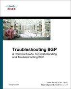
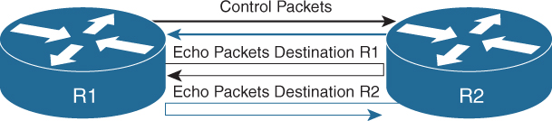
Asynchronous mode is the primary mode of operation and is mandatory for BFD to function. In this mode, each system periodically sends BFD control packets to one another. For example, packets send by router R1 have a source address of R1 and a destination address of router R2, as shown in Figure 14-4.

Each stream of BFD control packets is independent and does not follow a request response cycle. If a number of packets in a row are not received by the other system, then the session is declared down. An adaptive failure detection time is used to prevent false failures if a neighbor is sending packets slower than what it is advertising.
BFD Async packets are sent on UDP port 3784. The BFD source port must be in the range of 49152 through 65535. The BFD control packets contain the following fields:
![]() Version: Version of BFD control header. XR runs version 1 as default, but legacy sessions can run version 0 as well.
Version: Version of BFD control header. XR runs version 1 as default, but legacy sessions can run version 0 as well.
![]() Diag: A diagnostic code specifying the local system’s reason for the last change in session state, detection time expired, echo failed, and so on.
Diag: A diagnostic code specifying the local system’s reason for the last change in session state, detection time expired, echo failed, and so on.
![]() State: The current BFD session state as seen by the transmitting system.
State: The current BFD session state as seen by the transmitting system.
![]() P: Poll bit, if set, the transmitting system is requesting verification of connectivity, or of a parameter change, and is expecting a packet with the Final (F) bit in reply.
P: Poll bit, if set, the transmitting system is requesting verification of connectivity, or of a parameter change, and is expecting a packet with the Final (F) bit in reply.
![]() F: Final bit, if set, the transmitting system is responding to a received BFD Control packet that had the Poll (P) bit set.
F: Final bit, if set, the transmitting system is responding to a received BFD Control packet that had the Poll (P) bit set.
![]() Detect Multiplier: Detection time multiplier. The negotiated transmit interval, multiplied by this value, provides the detection time for the transmitting system in Asynchronous mode.
Detect Multiplier: Detection time multiplier. The negotiated transmit interval, multiplied by this value, provides the detection time for the transmitting system in Asynchronous mode.
![]() My Discriminator: A unique, nonzero discriminator value generated by the transmitting system, used to de-multiplex multiple BFD sessions between the same pair of systems.
My Discriminator: A unique, nonzero discriminator value generated by the transmitting system, used to de-multiplex multiple BFD sessions between the same pair of systems.
![]() Your Discriminator: The discriminator received from the corresponding remote system. This field reflects back the received value of My Discriminator, or is zero if that value is unknown.
Your Discriminator: The discriminator received from the corresponding remote system. This field reflects back the received value of My Discriminator, or is zero if that value is unknown.
![]() Desired Min TX Interval: This is the minimum interval, in microseconds, that the local system would like to use when transmitting BFD Control packets.
Desired Min TX Interval: This is the minimum interval, in microseconds, that the local system would like to use when transmitting BFD Control packets.
![]() Desired Min RX Interval: This is the minimum interval, in microseconds, between received BFD control packets that this system is capable of supporting.
Desired Min RX Interval: This is the minimum interval, in microseconds, between received BFD control packets that this system is capable of supporting.
![]() Required Min Echo RX Interval: This is the minimum interval, in microseconds, between received BFD Echo packets that this system is capable of supporting.
Required Min Echo RX Interval: This is the minimum interval, in microseconds, between received BFD Echo packets that this system is capable of supporting.
The BFD control packets as defined by IETF is shown in Figure 14-5.

BFD authentication is not supported on all platforms. BFD single-hop authentication is supported on IOS XE and NX-OS platforms.
Asynchronous Mode with Echo Function
Asynchronous mode with echo function is designed to test only the forwarding path and not the host stack on the remote system. It is enabled only after the session is enabled. BFD echo packets are sent in such a way that the other end just loops them back through its forwarding path. For example, a packet sent by router R1 could be sent with both the source and destination address belonging to R1 as shown in Figure 14-6.
Because echo packets do not require application or host stack processing on the remote end, it can be used for aggressive detection timers. Another benefit of using the echo function is that the sender has complete control of the response time. In order for the echo function to work, the remote node should also be capable of echo function. The BFD control packets with echo function enabled are sent as UDP packets with source and destination port 3785. Also, the interfaces running BFD with the echo function should be configured with the command no ip redirects.
Configuration and Verification
BFD is usually configured on a per-interface basis for the routing protocols that support BFD. BFD is enabled using the configuration bfd interval interval min_rx min_rx_interval multiplier multiplier. The variable interval is the transmit interval between BFD packets, whereas min_rx_interval is the minimum receive interval capability.
BFD can be enabled for BGP peer on Cisco IOS using the command neighbor ip-address fall-over bfd. On IOS XR, the command bfd fast-detect is part of the neighbor configuration. BFD for BGP can be enabled on NX-OS using the command bfd under the neighbor configuration. To be able to configure BFD, the feature bfd command should be configured to enable the BFD feature. To understand the BFD feature for BGP, examine the topology as shown in Figure 14-7. Router R1 has an EBGP peering with IOS XR router R2 and NX-OS router R3.

Example 14-14 demonstrates the configuration of BFD for BGP on all three Cisco operating systems. The asynchronous mode configuration is shown without the echo function, which was disabled manually. Some of the platforms have echo function enabled by default and thus require manual configuration to disable the echo function.
Example 14-14 BFD for BGP Configuration
R1
interface GigabitEthernet2/0/3
ip address 10.1.13.1 255.255.255.0
ip ospf 100 area 0
no ip redirects
bfd interval 300 min_rx 300 multiplier 3
no bfd echo
!
interface TenGigabitEthernet2/1/0
ip address 10.1.12.1 255.255.255.0
ip ospf 100 area 0
no ip redirects
bfd interval 300 min_rx 300 multiplier 3
no bfd echo
!
router bgp 100
bgp router-id 192.168.1.1
bgp log-neighbor-changes
no bgp default ipv4-unicast
neighbor 10.1.12.2 remote-as 200
neighbor 10.1.12.2 fall-over bfd
neighbor 10.1.13.3 remote-as 300
neighbor 10.1.13.3 fall-over bfd
!
address-family ipv4
neighbor 10.1.12.2 activate
neighbor 10.1.13.3 activate
exit-address-family
R2
interface TenGigE0/0/2/0
ipv4 address 10.1.12.2 255.255.255.0
!
bfd
interface TenGigE0/0/2/0
!
echo disable
!
router bgp 200
bgp router-id 192.168.2.2
address-family ipv4 unicast
!
neighbor 10.1.12.1
remote-as 100
bfd fast-detect
bfd multiplier 3
bfd minimum-interval 300
address-family ipv4 unicast
R3
feature bfd
feature bgp
!
interface Ethernet3/2
mpls ip
bfd interval 300 min_rx 300 multiplier 3
no bfd echo
no ip redirects
ip address 10.1.13.3/24
ip router ospf 100 area 0.0.0.0
no shutdown
!
router bgp 300
router-id 192.168.3.3
address-family ipv4 unicast
neighbor 10.1.13.2
bfd
remote-as 100
address-family ipv4 unicast
After the BGP session is up, the BFD session is also established. The BFD session is viewed using the command show bfd neighbors [details] on both Cisco IOS and NX-OS platforms. On IOS XR, use the command show bfd session [detail]. The detail command option displays more information on which client applications are using BFD and other details on the packets sent and received, and so on.
Example 14-15 examines the output of the command show bfd neighbors [detail] and show bfd session [detail]. In the output, notice that the BFD client is BGP. The BFD on all three platforms runs on version 1 by default. The BFD command output with detail keyword displays all the fields that are part of the BFD control packet. These fields can be very useful for debugging purposes and to understand whether there is a mismatch between the peers that could possibly cause BFD session to flap. Ensure that the State bit is set to Up rather than AdminDown. The output also shows that the echo function has been disabled, and the echo function interval value is 0.
Example 14-15 Verifying BFD Session
IOS
R1# show bfd neighbors
IPv4 Sessions
NeighAddr LD/RD RH/RS State Int
10.1.12.2 4097/2148073473 Up Up Te2/1/0
10.1.13.3 4098/1090519041 Up Up Gi2/0/3
R1# show bfd neighbors details
IPv4 Sessions
NeighAddr LD/RD RH/RS State Int
10.1.12.2 4097/2148073473 Up Up Te2/1/0
Session state is UP and not using echo function.
Session Host: Hardware
OurAddr: 10.1.12.1
Handle: 1
Local Diag: 0, Demand mode: 0, Poll bit: 0
MinTxInt: 300000, MinRxInt: 300000, Multiplier: 3
Received MinRxInt: 300000, Received Multiplier: 3
Holddown (hits): 677(0), Hello (hits): 300(62318)
Rx Count: 59338, Rx Interval (ms) min/max/avg: 5/312/277 last: 223 ms ago
Tx Count: 62317, Tx Interval (ms) min/max/avg: 5/304/264 last: 30 ms ago
Elapsed time watermarks: 0 0 (last: 0)
Registered protocols: BGP CEF
Uptime: 04:33:56
Last packet: Version: 1 - Diagnostic: 0
State bit: Up - Demand bit: 0
Poll bit: 0 - Final bit: 0
C bit: 1
Multiplier: 3 - Length: 24
My Discr.: 2148073473 - Your Discr.: 4097
Min tx interval: 300000 - Min rx interval: 300000
Min Echo interval: 0
IPv4 Sessions
NeighAddr LD/RD RH/RS State Int
10.1.13.3 4098/1090519041 Up Up Gi2/0/3
Session state is UP and not using echo function.
Session Host: Hardware
OurAddr: 10.1.13.1
Handle: 2
Local Diag: 0, Demand mode: 0, Poll bit: 0
MinTxInt: 300000, MinRxInt: 300000, Multiplier: 3
Received MinRxInt: 300000, Received Multiplier: 3
Holddown (hits): 891(0), Hello (hits): 300(3452)
Rx Count: 3029, Rx Interval (ms) min/max/avg: 296/304/300 last: 9 ms ago
Tx Count: 3451, Tx Interval (ms) min/max/avg: 1/302/264 last: 192 ms ago
Elapsed time watermarks: 0 0 (last: 0)
Registered protocols: BGP CEF
Uptime: 00:15:11
Last packet: Version: 1 - Diagnostic: 0
State bit: Up - Demand bit: 0
Poll bit: 0 - Final bit: 0
C bit: 0
Multiplier: 3 - Length: 24
My Discr.: 1090519041 - Your Discr.: 4098
Min tx interval: 300000 - Min rx interval: 300000
Min Echo interval: 50000
IOS XR
RP/0/RSP0/CPU0:R2# show bfd session
Interface Dest Addr Local det time(int*mult) State
Echo Async H/W NPU
------------------- --------------- ---------------- ---------------- ----------
Te0/0/2/0 10.1.12.1 0s(0s*0) 900ms(300ms*3) UP
No n/a
RP/0/RSP0/CPU0:R2# show bfd session detail
I/f: TenGigE0/0/2/0, Location: 0/0/CPU0
Dest: 10.1.12.1
Src: 10.1.12.2
State: UP for 0d:4h:41m:27s, number of times UP: 1
Session type: PR/V4/SH
Received parameters:
Version: 1, desired tx interval: 300 ms, required rx interval: 300 ms
Required echo rx interval: 300 ms, multiplier: 3, diag: None
My discr: 4097, your discr: 2148073473, state UP, D/F/P/C/A: 0/0/0/0/0
Transmitted parameters:
Version: 1, desired tx interval: 300 ms, required rx interval: 300 ms
Required echo rx interval: 0 ms, multiplier: 3, diag: None
My discr: 2148073473, your discr: 4097, state UP, D/F/P/C/A: 0/0/0/1/0
Timer Values:
Local negotiated async tx interval: 300 ms
Remote negotiated async tx interval: 300 ms
Desired echo tx interval: 0 s, local negotiated echo tx interval: 0 ms
Echo detection time: 0 ms(0 ms*3), async detection time: 900 ms(300 ms*3)
Local Stats:
Intervals between async packets:
Tx: Number of intervals=100, min=1 ms, max=302 ms, avg=139 ms
Last packet transmitted 103 ms ago
Rx: Number of intervals=100, min=225 ms, max=300 ms, avg=264 ms
Last packet received 61 ms ago
Intervals between echo packets:
Tx: Number of intervals=0, min=0 s, max=0 s, avg=0 s
Last packet transmitted 0 s ago
Rx: Number of intervals=0, min=0 s, max=0 s, avg=0 s
Last packet received 0 s ago
Latency of echo packets (time between tx and rx):
Number of packets: 0, min=0 ms, max=0 ms, avg=0 ms
Session owner information:
Desired Adjusted
Client Interval Multiplier Interval Multiplier
-------------------- --------------------- ---------------------
bgp-default 300 ms 3 300 ms 3
NX-OS
R3# show bfd neighbors
OurAddr NeighAddr LD/RD RH/RS Holdown(mult) State Int Vrf
10.1.13.3 10.1.13.1 1090519041/4098 Up 689(3) Up Eth3/2 default
R3# show bfd neighbors details
OurAddr NeighAddr LD/RD RH/RS Holdown(mult) State Int Vrf
10.1.13.3 10.1.13.1 1090519041/4098 Up 689(3) Up Eth3/2 default
Session state is Up and not using echo function
Local Diag: 0, Demand mode: 0, Poll bit: 0, Authentication: None
MinTxInt: 300000 us, MinRxInt: 300000 us, Multiplier: 3
Received MinRxInt: 300000 us, Received Multiplier: 3
Holdown (hits): 900 ms (0), Hello (hits): 300 ms (12449)
Rx Count: 14153, Rx Interval (ms) min/max/avg: 0/21232/265 last: 200 ms ago
Tx Count: 12449, Tx Interval (ms) min/max/avg: 296/296/296 last: 234 ms ago
Registered protocols: bgp
Uptime: 0 days 1 hrs 2 mins 12 secs
Last packet: Version: 1 - Diagnostic: 0
State bit: Up - Demand bit: 0
Poll bit: 0 - Final bit: 0
Multiplier: 3 - Length: 24
My Discr.: 4098 - Your Discr.: 1090519041
Min tx interval: 300000 - Min rx interval: 300000
Min Echo interval: 0 - Authentication bit: 0
Hosting LC: 3, Down reason: None, Reason not-hosted: None, Offloaded: No
Note
Although BFD can be enabled for IBGP sessions as well, it is better to have BFD implemented for IGP than for IBGP sessions. This is because the IBGP is typically established using routes learned from the IGP and is not typically configured between the directly connected neighbors.
An important thing to notice in R1’s BFD neighbors’ detail output is that the session host is Hardware. When the echo function is disabled, BFD is offloaded to hardware. Because BFD is a forwarding path failure detection protocol, it requires sending the BFD echo packets as low as 50 ms in order to reduce overall network convergence time. With multiple BFD sessions, it is hard to process such aggressive timers by the software. Thus, the BFD session gets offloaded to hardware and manages aggressive timers as low as 50ms. It is important to note that the echo function should be disabled in order to offload BFD into hardware. On Cisco IOS and IOS XE platforms, hardware offloaded BFD sessions are verified by using the show bfd neighbors details command or by using the show bfd neighbors hardware details command. If the echo function is enabled, BFD is not hardware offloaded and is processed by CPU (software).
On IOS XR, when the BFD hardware offload is enabled, the async control packets are not generated and received by the line card (LC) CPU but by the Network Processor (NP) on the line card, thus increasing the BFD scale. To enable hardware offload for BFD on ASR9k, use the command hw-module bfd-hw-offload enable location rack/slot/cpu from the admin config mode. After the command is configured, the line card previously mentioned is required to be reloaded before BFD hardware offload is enabled.
Note
BFD is offloaded onto LC by default on NX-OS platforms.
The BFD echo function is enabled by default on most of the Cisco platforms. To enable the echo function (if its disabled), use the command bfd echo on both Cisco IOS and NX-OS software under the interface configuration mode and use the command no echo disable to enable the echo mode globally or under the interface on IOS XR. When the session is configured with the echo function, the BFD session starts off in asynchronous mode using a slow interval of 2 seconds. After the session is up, and if the interval specified by the client is less than 2 seconds, the echo function gets activated (assuming the echo function is enabled on the remote peer as well).
Example 14-16 shows the command output for BFD neighbors when the echo function is enabled. In the output on router R1, the minimum echo interval shows the value of 1 ms. This is because this value is hard-coded to 1 ms, and if the echo function is supported on both ends, the actual echo tx interval for a session is maximum of the following:
1. Local desired echo tx interval.
2. Remote required minimum echo rx interval. (This value is obtained from incoming control packets.)
Example 14-16 BFD Neighbors with Echo Function
IOS
R1# show bfd neighbors details
IPv4 Sessions
NeighAddr LD/RD RH/RS State Int
10.1.12.2 4098/2148073473 Up Up Te2/1/0
Session state is UP and using echo function with 300 ms interval.
Session Host: Software
OurAddr: 10.1.12.1
Handle: 2
Local Diag: 0, Demand mode: 0, Poll bit: 0
MinTxInt: 1000000, MinRxInt: 1000000, Multiplier: 3
Received MinRxInt: 2000000, Received Multiplier: 3
Holddown (hits): 0(0), Hello (hits): 2000(4)
Rx Count: 7, Rx Interval (ms) min/max/avg: 5/1951/1293 last: 798 ms ago
Tx Count: 5, Tx Interval (ms) min/max/avg: 1525/1941/1733 last: 1625 ms ago
Elapsed time watermarks: 0 0 (last: 0)
Registered protocols: BGP CEF
Uptime: 00:00:08
Last packet: Version: 1 - Diagnostic: 0
State bit: Up - Demand bit: 0
Poll bit: 0 - Final bit: 0
C bit: 1
Multiplier: 3 - Length: 24
My Discr.: 2148073473 - Your Discr.: 4098
Min tx interval: 2000000 - Min rx interval: 2000000
Min Echo interval: 1000
! Output omitted for brevity
IOS XR
RP/0/RSP0/CPU0:R2# show bfd session detail
I/f: TenGigE0/0/2/0, Location: 0/0/CPU0
Dest: 10.1.12.1
Src: 10.1.12.2
State: UP for 0d:0h:2m:12s, number of times UP: 6
Session type: PR/V4/SH
Received parameters:
Version: 1, desired tx interval: 1 s, required rx interval: 1 s
Required echo rx interval: 300 ms, multiplier: 3, diag: None
My discr: 4098, your discr: 2148073473, state UP, D/F/P/C/A: 0/0/0/0/0
Transmitted parameters:
Version: 1, desired tx interval: 2 s, required rx interval: 2 s
Required echo rx interval: 1 ms, multiplier: 3, diag: None
My discr: 2148073473, your discr: 4098, state UP, D/F/P/C/A: 0/0/0/1/0
Timer Values:
Local negotiated async tx interval: 2 s
Remote negotiated async tx interval: 2 s
Desired echo tx interval: 300 ms, local negotiated echo tx interval: 300 ms
Echo detection time: 900 ms(300 ms*3), async detection time: 6 s(2 s*3)
! Output omitted for brevity
NX-OS
R3# show bfd neighbors details
OurAddr NeighAddr LD/RD RH/RS Holdown(mult) State Int Vrf
10.1.13.3 10.1.13.1 1090519041/4098 Up 689(3) Up Eth3/2 default
Session state is Up and using echo function with 300 ms interval
Local Diag: 0, Demand mode: 0, Poll bit: 0, Authentication: None
MinTxInt: 300000 us, MinRxInt: 2000000 us, Multiplier: 3
Received MinRxInt: 1000000 us, Received Multiplier: 3
Holdown (hits): 6000 ms (5), Hello (hits): 1000 ms (332494)
Rx Count: 320684, Rx Interval (ms) min/max/avg: 0/10634/269 last: 1370 ms ago
Tx Count: 332494, Tx Interval (ms) min/max/avg: 756/756/756 last: 190 ms ago
Registered protocols: bgp
Uptime: 0 days 0 hrs 1 mins 52 secs
Last packet: Version: 1 - Diagnostic: 0
State bit: Up - Demand bit: 0
Poll bit: 0 - Final bit: 0
Multiplier: 3 - Length: 24
My Discr.: 4097 - Your Discr.: 1090519042
Min tx interval: 1000000 - Min rx interval: 1000000
Min Echo interval: 300000 - Authentication bit: 0
Hosting LC: 3, Down reason: None, Reason not-hosted: None, Offloaded: No
IOS XR has support for viewing the packet counters in a detailed manner at the line card level using the command show bfd counters packet private detail location rack/slot/cpu. Example 14-17 displays the counters for BFD control packets on IOS XR.
Example 14-17 BFD Packet Counters
IOS XR
RP/0/RSP0/CPU0:R2# show bfd counters packet private detail location 0/0/CPU0
TenGigE0/0/2/0 Recv Rx Invalid Xmit Delta
Async: 406384 0 387357
Echo: 15030 0 15030 0
Troubleshooting BFD Issues
Issues with BFD can cause convergence issues; thus, this section discusses some of the most common issues seen with BFD.
BFD Session Not Coming Up
Perform the following steps to verify why the BFD session is not coming up:
Step 1. Verify the application that created the BFD. If the application is BGP, ensure that BFD is properly configured with the same interval and multiplier value on both sides.
Step 2. Verify there is reachability to the remote with which the BFD session is being established. Ensure there is proper adjacency and reachability between the two peering devices.
Step 3. If the reachability is there, but the BFD session is not coming up, verify the received and sent counters on each side of the BFD neighbors and continue with the following:
![]() Ensure there is no ACL that is blocking the BFD packets, that is, UDP ports 3784 and 3785.
Ensure there is no ACL that is blocking the BFD packets, that is, UDP ports 3784 and 3785.
![]() Verify if the line card supports the aggressive timers (if configured) and also that the line card and the RP are not hitting any resource limitation. For this, refer to the hardware data sheet on Cisco.com.
Verify if the line card supports the aggressive timers (if configured) and also that the line card and the RP are not hitting any resource limitation. For this, refer to the hardware data sheet on Cisco.com.
![]() On IOS XR, check which NP corresponds to which interface and if the NP is receiving BFD packets or not. This can be done using the following commands:
On IOS XR, check which NP corresponds to which interface and if the NP is receiving BFD packets or not. This can be done using the following commands:
show controllers np ports all location rack/slot/cpu
show controllers np counters np location rack/slot/cpu | include
“Rate|BFD”
show uidb data location rack/slot/cpu interface ingress
show uidb location rack/slot/cpu interface ing-extension
![]() On NX-OS, verify the event-history for any events or errors.
On NX-OS, verify the event-history for any events or errors.
show system internal bfd event-history [all | error | session]
![]() On IOS XR, verify the BFD traces for any errors or events.
On IOS XR, verify the BFD traces for any errors or events.
show bfd trace [event | error]
![]() Verify if there is any CoPP policy dropping BFD packets. Ensure that BFD packets are treated in a separate class-map under the CoPP policy.
Verify if there is any CoPP policy dropping BFD packets. Ensure that BFD packets are treated in a separate class-map under the CoPP policy.
![]() On IOS XR, verify that the BFD packets are not exceeding the LPTS limit for BFD control packets.
On IOS XR, verify that the BFD packets are not exceeding the LPTS limit for BFD control packets.
BFD Session Flapping
Perform the following steps to troubleshoot BFD issues if the BFD session is flapping:
Step 1. Ensure that the link is not getting congested or oversubscribed.
Step 2. Ensure that BFD is part of the priority queue in QoS configs, and proper resource allocation is given to the BFD class.
Step 3. Ensure that the BFD adjacency is stable. This is usually seen in scenarios after RP switchovers.
Step 4. On IOS XR, ensure that the bfd_agent process is not respawning.
Step 5. Ensure the BFD packets are hardware switched on NX-OS—not software switched and thus getting delayed or dropped. This can be due to hardware misprogramming as well. Also, ensure no ip redirects command is configured under the interfaces.
Step 6. Ensure there is no control plane congestion and there is no configuration that remarks BFD packets from the default IP precedence value of 6, because this will affect the Rx handling of control packets. Verify the queueing policies on the egress to ensure that BFD is not delayed or dropped.
For BFD-related issues, the following outputs can be collected during the problematic state:
![]() On IOS XR
On IOS XR
![]() show tech routing bfd
show tech routing bfd
![]() On NX-OS
On NX-OS
![]() show tech bfd
show tech bfd
BGP Fast-External-Fallover
Historically, when the fast-external-fallover feature was not available and a link went down, the EBGP session remained up until the hold-down timer expired. This situation used to cause a traffic black hole situation and service impact. To overcome this problem, bgp fast-external-fallover command was introduced. With this command configured, the EBGP session terminates immediately if the link goes down. This command is enabled by default on recent IOS releases, and IOS XR and NX-OS releases.
This feature is enabled by default for EBGP sessions but disabled for IBGP sessions. The feature can also be enabled at the interface level using the command ip bgp fast-external-fallover on Cisco IOS software.
Although the command bgp fast-external-fallover improves on convergence time, it is good to disable the command if the EBGP link is flapping continuously. By disabling fast-fallover, the instability caused by neighbors continually transitioning between idle and established states and the routing churn caused by the flood of ADVERTISE and WITHDRAW messages can be avoided. Use the no bgp fast-external-fallover command to disable this feature on both Cisco IOS and NX-OS, and use the command bgp fast-external-fallover disable command to disable this feature on IOS XR.
BGP Add-Path
In BGP, only one best path is advertised by a BGP router or a BGP RR. The BGP speaker accepts only one path for a given prefix from a given peer. If a BGP speaker receives multiple paths for the same prefix, then because of BGP’s implicit withdraw semantics, the latest announcement of the prefix replaces the previous announcements. Even when multipath is configured, BGP RR does not advertise multiple paths but only the best path. This prevents the efficient use of the BGP multipath feature. Also, because of this behavior there could be other side effects, such as Multi-Exit Discriminator (MED) oscillations, suboptimal hot potato routing, and the like.
To understand the default behavior of BGP with multiple paths, examine the topology shown in Figure 14-8. It will be used for all future examples. RR1 is an RR running Cisco IOS, RR2 is running IOS XR, and RR3 is running NX-OS. All the other routers are running Cisco IOS software.

In Figure 14-8, the prefix 172.16.4.4/32 is being advertised by CE2, which is in AS-300. The prefix is learned in AS-100 via two paths: one via PE2 and the other via PE3. Although there are two paths for the prefix, only the best path is advertised to the RR. Even if the RR has multiple paths, it hides all but the best path. Thus the ingress routers most often know about one exit point. When that path fails, traffic loss is proportional to control-plane convergence.
The solution to such issues is having a diverse path available to the ingress router, so that the convergence time is not high. Some of the BGP diverse path features were discussed in Chapter 6, “Troubleshooting Platform Issues Due to BGP.” One of the other features to achieve the diverse path is the BGP add-path feature. The BGP add-path feature signals not only the primary and backup path but the diverse paths ranging from 2 to n or all paths available for the prefix. To implement BGP add-path feature, both the RRs and the edge BGP router should have add-path feature support.
The BGP add-path features provides a lot of benefits to the network as a whole. A few of the benefits are as follows:
![]() Fast Convergence: Because the ingress routers now have visibility to more paths, they can switch to backup paths faster after the primary path fails.
Fast Convergence: Because the ingress routers now have visibility to more paths, they can switch to backup paths faster after the primary path fails.
![]() Load Balancing: Because there is more visibility for the paths to the ingress routers, they can do equal cost multipath (ECMP) on multiple paths to achieve load balancing. This requires either the advertisement of backup paths or all paths to be advertised.
Load Balancing: Because there is more visibility for the paths to the ingress routers, they can do equal cost multipath (ECMP) on multiple paths to achieve load balancing. This requires either the advertisement of backup paths or all paths to be advertised.
![]() Churn Reduction: Withdraws can be suppressed because of available alternate paths.
Churn Reduction: Withdraws can be suppressed because of available alternate paths.
![]() Route Oscillation Prevention: Route oscillation scenarios are covered in RFC 3345. The scenarios presented in the RFC can be overcome by advertising group best paths (in some cases all paths).
Route Oscillation Prevention: Route oscillation scenarios are covered in RFC 3345. The scenarios presented in the RFC can be overcome by advertising group best paths (in some cases all paths).
The BGP add-path feature is defined in RFC 7911. The RFC proposes an extension to the Network Layer Reachability Information (NLRI) by including path-ID, so that multiple paths for the same prefix can be advertised. Path-IDs are unique to a peering session and are generated for each network. The encodings specified in RFC 4271 and RFC 4760 are extended, as shown in Figure 14-9.

For carrying labeled prefixes, the encoding specified in RFC 3107 is modified for the add-path feature, as shown in Figure 14-10.

The add-path feature is negotiated as a capability on a per AFI/SAFI basis and done separately for both Send and Receive direction. The per AFI and per neighbor configuration triggers capability exchange with the peers. For exchanging add-path capability between two routers—for instance, router A and router B, both A and B should configure the add-path capability to send, receive, or both.
For router A to send add-paths to router B, router A should enable send capability and router B should enable receive capability. Similarly, for router A to receive add-paths from router B, router A should be configured with receive capability and router B with the send capability. Any configuration changes will take effect only during the next session establishment.
The add-path capability is configured in two ways. It can either be configured globally under the address-family or on a per-neighbor basis. To enable the BGP add-path capability, use the command bgp additional-paths [send | receive] under the address-family. Cisco IOS routers reset the session as soon as the command is configured, but it is manually required on IOS XR and NX-OS to clear the BGP session to exchange add-path capability.
Example 14-18 illustrates the configuration to exchange BGP add-path capability on all three platforms. In this example, all the RR routers are configured to both send and receive add-path capability. The PE1 router is globally configured to both send and receive add-path capability but configured to receive add-path only from the RR1 router.
Example 14-18 BGP Add-Path Capability Configuration
RR1
RR1(config)# router bgp 100
RR1(config-router)# address-family ipv4 unicast
RR1(config-router-af)# bgp additional-paths send receive
RR2
RP/0/0/CPU0:RR2(config)# router bgp 100
RP/0/0/CPU0:RR2(config-bgp)# address-family ipv4 unicast
RP/0/0/CPU0:RR2(config-bgp-af)# additional-paths send
RP/0/0/CPU0:RR2(config-bgp-af)# additional-paths receive
RP/0/0/CPU0:RR2(config-bgp-af)# commit
RR3
RR3(config)# router bgp 100
RR3(config-router)# address-family ipv4 unicast
RR3(config-router-af)# additional-paths send
RR3(config-router-af)# additional-paths receive
PE1
PE1(config)# router bgp 100
PE1(config-router)# address-family ipv4 unicast
PE1(config-router-af)# bgp additional-paths send receive
PE1(config-router-af)# neighbor 192.168.11.11 additional-paths receive
After the BGP session is reset, the add-path capability is negotiated and is viewed under the command show bgp afi safi neighbor ip-address. Example 14-19 displays the add-path capability negotiated on all the RR routers and PE1 router. The output shows that PE1 is exchanging only receive capability with RR1 and both send and receive capability with RR2 and RR3 (based on the configuration under the AFI).
Example 14-19 Verifying BGP Add-Path Capability
RR1
RR1# show bgp ipv4 unicast neighbors 192.168.1.1
BGP neighbor is 192.168.1.1, remote AS 100, internal link
BGP version 4, remote router ID 192.168.1.1
BGP state = Established, up for 00:07:05
Last read 00:00:49, last write 00:00:34, hold time is 180, keepalive interval is
60 seconds
Neighbor sessions:
1 active, is not multisession capable (disabled)
Neighbor capabilities:
Route refresh: advertised and received(new)
Four-octets ASN Capability: advertised and received
Address family IPv4 Unicast: advertised and received
Enhanced Refresh Capability: advertised and received
Multisession Capability:
Stateful switchover support enabled: NO for session 1
. . .
. . .
For address family: IPv4 Unicast
Additional Paths send capability: advertised
Additional Paths receive capability: advertised and received
Session: 192.168.1.1
BGP table version 8, neighbor version 8/0
! Output omitted for brevity
RR2
RP/0/0/CPU0:RR2# show bgp ipv4 unicast neighbors 192.168.1.1
Fri May 20 03:23:58.765 UTC
BGP neighbor is 192.168.1.1
Remote AS 100, local AS 100, internal link
Remote router ID 192.168.1.1
Cluster ID 192.168.22.22
BGP state = Established, up for 00:07:07
NSR State: None
. . .
. . .
For Address Family: IPv4 Unicast
BGP neighbor version 8
Update group: 0.1 Filter-group: 0.2 No Refresh request being processed
Route-Reflector Client
AF-dependent capabilities:
Additional-paths Send: advertised and received
Additional-paths Receive: advertised and received
! Output omitted for brevity
RR3
RR3# show bgp ipv4 unicast neighbors 192.168.1.1
BGP neighbor is 192.168.1.1, remote AS 100, ibgp link, Peer index 1
BGP version 4, remote router ID 192.168.1.1
BGP state = Established, up for 00:01:28
Using loopback0 as update source for this peer
Last read 00:00:32, hold time = 180, keepalive interval is 60 seconds
Last written 00:00:27, keepalive timer expiry due 00:00:32
Received 661 messages, 1 notifications, 0 bytes in queue
Sent 613 messages, 0 notifications, 0 bytes in queue
Connections established 4, dropped 3
Last reset by peer 00:01:36, due to session closed
Last reset by us never, due to No error
Neighbor capabilities:
Dynamic capability: advertised (mp, refresh, gr)
Dynamic capability (old): advertised
. . .
. . .
Additional Paths capability: advertised received
Additional Paths Capability Parameters:
Send capability advertised to Peer for AF:
IPv4 Unicast
Receive capability advertised to Peer for AF:
IPv4 Unicast
Send capability received from Peer for AF:
IPv4 Unicast
Receive capability received from Peer for AF:
IPv4 Unicast
! Output omitted for brevity
PE1
PE1# show bgp ipv4 unicast neighbors 192.168.11.11
BGP neighbor is 192.168.11.11, remote AS 100, internal link
BGP version 4, remote router ID 192.168.11.11
BGP state = Established, up for 00:28:35
. . .
. . .
For address family: IPv4 Unicast
Additional Paths send capability: received
Additional Paths receive capability: advertised and received
! Output omitted for brevity
Because RR receives multiple paths from the border or edge routers, the RR router performs the best-path computation for 2 to N paths or all paths and sends the N or all paths to the border routers. The number N is limited to 2 for IOS XR and up to 3 on Cisco IOS to preserve CPU and improved convergence. If there is multipath configured, the RR router performs the best path and send all the multipaths to the border routers.
Note
If the add-path policy is defined under the vpnv4 address-family, the policy applies to all the VRFs unless it is overridden at individual VRFs.
Now, to advertise the backup paths or additional paths from the RR, two steps should be followed:
Step 1. Make a selection of additional paths on the RR.
Step 2. Install the additional paths on the border router.
For making a selection of additional paths, use the command bgp additional-paths select [all | backup | best | group-best] on Cisco IOS. On IOS XR and NX-OS, use the additional-paths selection command under the address-family with a route policy or a route-map. Under the policy, all the options are available for advertising the backup or all paths for the prefix and also installing them locally. The Table 14-1 lists the purpose of the available options with the path selection.

Example 14-20 illustrates the configuration on all three RRs to make the path selection for advertising it toward the border router PE1. Even though the RR routers are advertising the backup or additional paths, PE1 only installs the backup paths when the bgp additional-paths install command is configured under the address-family.
Example 14-20 Additional Path Selection Configuration on RRs
RR1
RR1(config)# router bgp 100
RR1(config-router)# address-family ipv4 unicast
RR1(config-router-af)# bgp additional-paths select ?
all Select all available paths
backup Select backup path
best Select best N paths
best-external Select best-external path
group-best Select group-best path
RR1(config-router-af)# bgp additional-paths select best 2
RR2
RP/0/0/CPU0:RR2(config)# router bgp 100
RP/0/0/CPU0:RR2(config-bgp)# address-family ipv4 unicast
RP/0/0/CPU0:RR2(config-bgp-af)# additional-paths selection route-policy ADD_PATH
RP/0/0/CPU0:RR2(config-bgp-af)# exit
RP/0/0/CPU0:RR2(config-bgp)# exit
RP/0/0/CPU0:RR2(config)# route-policy ADD_PATH
RP/0/0/CPU0:RR2(config-rpl)# if destination in (172.16.4.4/32) then
RP/0/0/CPU0:RR2(config-rpl-if)# set path-selection backup 1 advertise
RP/0/0/CPU0:RR2(config-rpl-if)# endif
RP/0/0/CPU0:RR2(config-rpl)# end-policy
RP/0/0/CPU0:RR2(config)# commit
RR3
RR3(config)# router bgp 100
RR3(config-router)# address-family ipv4 unicast
RR3(config-router-af)# additional-paths selection route-map ADD_PATH
RR3(config-router-af)# additional-paths install backup
RR3(config-router-af)# exit
RR3(config-router)# route-map ADD_PATH permit 10
RR3(config-route-map)# match ip address prefix-list fromCE2
RR3(config-route-map)# set path-selection all advertise
PE1
PE1(config)# router bgp 100
PE1(config-router)# address-family ipv4 unicast
PE1(config-router-af)# bgp additional-paths install
Note
The command bgp additional-paths install on Cisco IOS and the command option additional-paths install on IOS XR and NX-OS are only for demonstration purposes here. These are not part of the BGP Add-Path feature but are used in the BGP Prefix-Independent Convergence feature discussed later in this chapter.
After PE1 is configured to install the additional paths, PE1 receives a total of six paths from the three RRs. Of the six paths, one path is selected as best, and one is selected as the backup/repair path. Example 14-21 displays the output showing multiple paths received on the PE1 router from all the RRs.
Example 14-21 BGP Table on PE1
PE1# show bgp ipv4 unicast 172.16.4.4
BGP routing table entry for 172.16.4.4/32, version 7
Paths: (6 available, best #6, table default)
Additional-path-install
Not advertised to any peer
Refresh Epoch 1
300
192.168.3.3 (metric 3) from 192.168.22.22 (192.168.22.22)
Origin IGP, metric 0, localpref 100, valid, internal
Originator: 192.168.3.3, Cluster list: 192.168.22.22
rx pathid: 0x2, tx pathid: 0
Refresh Epoch 1
300
192.168.3.3 (metric 3) from 192.168.33.33 (192.168.33.33)
Origin IGP, metric 0, localpref 100, valid, internal
Originator: 192.168.3.3, Cluster list: 192.168.33.33
rx pathid: 0x2, tx pathid: 0
Refresh Epoch 3
300
192.168.3.3 (metric 3) from 192.168.11.11 (192.168.11.11)
Origin IGP, metric 0, localpref 100, valid, internal, backup/repair
Originator: 192.168.3.3, Cluster list: 192.168.11.11
rx pathid: 0x1, tx pathid: 0
Refresh Epoch 1
300
192.168.2.2 (metric 3) from 192.168.22.22 (192.168.22.22)
Origin IGP, metric 0, localpref 100, valid, internal
Originator: 192.168.2.2, Cluster list: 192.168.22.22
rx pathid: 0x1, tx pathid: 0
Refresh Epoch 1
300
192.168.2.2 (metric 3) from 192.168.33.33 (192.168.33.33)
Origin IGP, metric 0, localpref 100, valid, internal
Originator: 192.168.2.2, Cluster list: 192.168.33.33
rx pathid: 0x1, tx pathid: 0
Refresh Epoch 3
300
192.168.2.2 (metric 3) from 192.168.11.11 (192.168.11.11)
Origin IGP, metric 0, localpref 100, valid, internal, best
Originator: 192.168.2.2, Cluster list: 192.168.11.11
rx pathid: 0x0, tx pathid: 0x0
On the RR routers, BGP selects a best path and second-best path and installs in the BGP table and RIB. Example 14-22 displays the prefix information on all the RR routers. Because the route policy is configured to advertise the additional path on RR1, RR2, and RR3 routers, all the RRs don’t just advertise the best path but also advertise additional paths. On RR1, the prefix 172.16.4.4 is advertised as the best as well as the additional path learned from another PE router. Both RR2 and RR3 show both the paths being advertised to the neighbors or route reflector-client router PE1: 192.168.1.1.
Example 14-22 Prefix Information
RR1
RR1# show bgp ipv4 unicast 172.16.4.4
BGP routing table entry for 172.16.4.4/32, version 14
Paths: (2 available, best #1, table default)
Path advertised to update-groups:
2 6
Refresh Epoch 2
300, (Received from a RR-client)
192.168.2.2 (metric 2) from 192.168.2.2 (192.168.2.2)
Origin IGP, metric 0, localpref 100, valid, internal, best
rx pathid: 0, tx pathid: 0x0
Path advertised to update-groups:
6
Refresh Epoch 2
300, (Received from a RR-client)
192.168.3.3 (metric 2) from 192.168.3.3 (192.168.3.3)
Origin IGP, metric 0, localpref 100, valid, internal, best2
rx pathid: 0, tx pathid: 0x1
RR1# show bgp ipv4 unicast neighbors 192.168.1.1 advertised-routes
BGP table version is 88, local router ID is 192.168.11.11
Status codes: s suppressed, d damped, h history, * valid, > best, i - internal,
r RIB-failure, S Stale, m multipath, b backup-path, f RT-Filter,
x best-external, a additional-path, c RIB-compressed,
Origin codes: i - IGP, e - EGP, ? - incomplete
RPKI validation codes: V valid, I invalid, N Not found
Network Next Hop Metric LocPrf Weight Path
*>i 172.16.4.4/32 192.168.2.2 0 100 0 300 i
* ia172.16.4.4/32 192.168.3.3 0 100 0 300 i
Total number of prefixes 2
RR2
RP/0/0/CPU0:RR2# show bgp ipv4 unicast 172.16.4.4
BGP routing table entry for 172.16.4.4/32
Versions:
Process bRIB/RIB SendTblVer
Speaker 11 11
Last Modified: May 20 07:51:28.941 for 00:53:25
Paths: (2 available, best #1)
Advertised to update-groups (with more than one peer):
0.2
Advertised to peers (in unique update groups):
192.168.1.1
Path #1: Received by speaker 0
Advertised to update-groups (with more than one peer):
0.2
Advertised to peers (in unique update groups):
192.168.1.1
300, (Received from a RR-client)
192.168.2.2 (metric 2) from 192.168.2.2 (192.168.2.2)
Origin IGP, metric 0, localpref 100, valid, internal, best, group-best
Received Path ID 0, Local Path ID 1, version 11
Path #2: Received by speaker 0
Advertised to peers (in unique update groups):
192.168.1.1
300, (Received from a RR-client)
192.168.3.3 (metric 2) from 192.168.3.3 (192.168.3.3)
Origin IGP, metric 0, localpref 100, valid, internal, backup, add-path
Received Path ID 0, Local Path ID 2, version 11
RR3
RR3# show bgp ipv4 unicast 172.16.4.4
BGP routing table information for VRF default, address family IPv4 Unicast
BGP routing table entry for 172.16.4.4/32, version 78
Paths: (2 available, best #2)
Flags: (0x08001a) on xmit-list, is in urib, is best urib route, is in HW,
Advertised path-id 2
Path type: internal, path is valid, not best reason: Router Id
AS-Path: 300 , path sourced external to AS
192.168.3.3 (metric 41) from 192.168.3.3 (192.168.3.3)
Origin IGP, MED 0, localpref 100, weight 0
Advertised path-id 1
Path type: internal, path is valid, is best path
AS-Path: 300 , path sourced external to AS
192.168.2.2 (metric 41) from 192.168.2.2 (192.168.2.2)
Origin IGP, MED 0, localpref 100, weight 0
Path-id 1 advertised to peers:
192.168.1.1 192.168.3.3
Path-id 2 advertised to peers:
192.168.1.1
If for some reason, either one of the RRs goes down or if the bgp additional-paths select best command is removed from RR1 router, PE1 selects the backup path learned via other RR. Example 14-23 demonstrates a negative testing by removing the command bgp additional-paths select best from RR1 router. PE1 router selects the backup path from RR2 router while the primary path is still being learned from RR1.
Example 14-23 BGP Additional-Path Select Command Testing
RR1
RR1(config)# router bgp 100
RR1(config-router)# address-family ipv4 unicast
RR1(config-router-af)# no bgp additional-paths select best 2
PE1
PE1# show bgp ipv4 unicast 172.16.4.4
BGP routing table entry for 172.16.4.4/32, version 13
Paths: (5 available, best #5, table default)
Multipath: eBGP
Additional-path-install
Not advertised to any peer
Refresh Epoch 1
300
192.168.3.3 (metric 3) from 192.168.22.22 (192.168.22.22)
Origin IGP, metric 0, localpref 100, valid, internal, backup/repair
Originator: 192.168.3.3, Cluster list: 192.168.22.22
rx pathid: 0x2, tx pathid: 0
Refresh Epoch 1
300
192.168.3.3 (metric 3) from 192.168.33.33 (192.168.33.33)
Origin IGP, metric 0, localpref 100, valid, internal
Originator: 192.168.3.3, Cluster list: 192.168.33.33
rx pathid: 0x2, tx pathid: 0
Refresh Epoch 1
300
192.168.2.2 (metric 3) from 192.168.22.22 (192.168.22.22)
Origin IGP, metric 0, localpref 100, valid, internal
Originator: 192.168.2.2, Cluster list: 192.168.22.22
rx pathid: 0x1, tx pathid: 0
Refresh Epoch 1
300
192.168.2.2 (metric 3) from 192.168.33.33 (192.168.33.33)
Origin IGP, metric 0, localpref 100, valid, internal
Originator: 192.168.2.2, Cluster list: 192.168.33.33
rx pathid: 0x1, tx pathid: 0
Refresh Epoch 4
300
192.168.2.2 (metric 3) from 192.168.11.11 (192.168.11.11)
Origin IGP, metric 0, localpref 100, valid, internal, best
Originator: 192.168.2.2, Cluster list: 192.168.11.11
rx pathid: 0x0, tx pathid: 0x0
BGP best-external
After examining the topology shown in Figure 14-8 and looking at all the outputs from the add-path examples, PE2 was chosen as the best path because of its lowest router-id. With the add-path feature on the RR routers, both the primary and backup paths are being advertised via RR. Both PE2 and PE3 select the best path that it learns directly from their peering with CE2.
But what happens if the default BGP routing policy is modified? For example, if the path from PE2 is set with a local preference of 200, PE3 instead of having the best path learned via CE2, it will have the best path learned via PE2. So, even if the RR advertises the primary and the backup paths to the remote border router, there is actually a single path via the PE2 router.
After examining the BGP table for the prefix 172.16.4.4, notice that the best path on PE3 is also being learned from PE2 and not from the direct link between CE2 and PE3. Example 14-24 displays the BGP table for the prefix 172.16.4.4/32 on both PE2 and PE3 routers.
Example 14-24 BGP Table Output
PE2
PE2# show bgp ipv4 unicast 172.16.4.4
BGP routing table entry for 172.16.4.4/32, version 9
Paths: (1 available, best #1, table default)
Advertised to update-groups:
3
Refresh Epoch 3
300
172.16.24.4 from 172.16.24.4 (172.16.4.4)
Origin IGP, metric 0, localpref 200, valid, external, best
rx pathid: 0, tx pathid: 0x0
PE3
PE3# show bgp ipv4 unicast 172.16.4.4
BGP routing table entry for 172.16.4.4/32, version 10
Paths: (4 available, best #1, table default)
Advertised to update-groups:
2
Refresh Epoch 2
300
192.168.2.2 (metric 3) from 192.168.11.11 (192.168.11.11)
Origin IGP, metric 0, localpref 200, valid, internal, best
Originator: 192.168.2.2, Cluster list: 192.168.11.11
rx pathid: 0, tx pathid: 0x0
Refresh Epoch 1
300
192.168.2.2 (metric 3) from 192.168.33.33 (192.168.33.33)
Origin IGP, metric 0, localpref 200, valid, internal
Originator: 192.168.2.2, Cluster list: 192.168.33.33
rx pathid: 0, tx pathid: 0
Refresh Epoch 1
300
192.168.2.2 (metric 3) from 192.168.22.22 (192.168.22.22)
Origin IGP, metric 0, localpref 200, valid, internal
Originator: 192.168.2.2, Cluster list: 192.168.22.22
rx pathid: 0, tx pathid: 0
Refresh Epoch 6
300
172.16.34.4 from 172.16.34.4 (172.16.4.4)
Origin IGP, metric 0, localpref 100, valid, external
rx pathid: 0, tx pathid: 0
To overcome this behavior, the BGP best-external feature was introduced. The BGP best-external functionality is defined in IETF draft draft-ietf-idr-best-external. Using this feature, the backup PE router propagates its own best external route—the path directly learned from CE, and not via another PE, to the RRs or IBGP peers. The BGP table on the backup PE still shows the best path via another PE but also shows the external path as the backup/repair path.
To enable the BGP best-external feature, use the command bgp advertise-best-external on the backup PE router. This command enables BGP to treat an external route as the best backup path, install the best external as a backup path, and advertise that using BGP updates. It is not needed to configure or enable the bgp additional-paths command to enable BGP best-external functionality, because the installation of backup path functionality is rolled into the bgp advertise-best-external command.
Example 14-25 demonstrates the configuration of the BGP best-external feature on both IOS and IOS XR platforms.
Example 14-25 BGP Best-External Configuration
IOS
PE3(config)# router bgp 100
PE3(config-router)# address-family ipv4 unicast
PE3(config-router-af)# bgp advertise-best-external
IOS XR
PE3(config)# router bgp 100
PE3(config-bgp)# address-family ipv4 unicast
PE3(config-bgp-af)# advertise-best-external
After PE3 is configured to advertise the best-external path, RRs receive the primary path via PE2 and the backup/repair path via PE3 that is the best-external path. Examine the output of the BGP table for the prefix 172.16.4.4 on the PE3 router in Example 14-26. Prefix 172.16.4.4 on PE3 has the best path via PE2; the external path via CE2 is marked as backup/repair and advertise-best-external. Also, the command show bgp ipv4 unicast neighbors ip-address advertised-routes displays the advertised prefix, which is marked as b and x, where b represents the backup path and x represents the best-external path.
Example 14-26 Verifying BGP Best-External Path
PE3# show bgp ipv4 unicast 172.16.4.4
BGP routing table entry for 172.16.4.4/32, version 12
Paths: (4 available, best #1, table default)
Advertise-best-external
Advertised to update-groups:
1 2
Refresh Epoch 3
300
192.168.2.2 (metric 3) from 192.168.11.11 (192.168.11.11)
Origin IGP, metric 0, localpref 200, valid, internal, best
Originator: 192.168.2.2, Cluster list: 192.168.11.11
rx pathid: 0, tx pathid: 0x0
Refresh Epoch 1
300
192.168.2.2 (metric 3) from 192.168.33.33 (192.168.33.33)
Origin IGP, metric 0, localpref 200, valid, internal
Originator: 192.168.2.2, Cluster list: 192.168.33.33
rx pathid: 0, tx pathid: 0
Refresh Epoch 1
300
192.168.2.2 (metric 3) from 192.168.22.22 (192.168.22.22)
Origin IGP, metric 0, localpref 200, valid, internal
Originator: 192.168.2.2, Cluster list: 192.168.22.22
rx pathid: 0, tx pathid: 0
Refresh Epoch 7
300
172.16.34.4 from 172.16.34.4 (172.16.4.4)
Origin IGP, metric 0, localpref 100, valid, external, backup/repair,
advertise-best-external , recursive-via-connected
rx pathid: 0, tx pathid: 0
! The below output shows the advertised path to RR1 router
PE3# show bgp ipv4 unicast neighbors 192.168.11.11 advertised-routes
BGP table version is 12, local router ID is 192.168.3.3
Status codes: s suppressed, d damped, h history, * valid, > best, i - internal,
r RIB-failure, S Stale, m multipath, b backup-path, f RT-Filter,
x best-external, a additional-path, c RIB-compressed,
Origin codes: i - IGP, e - EGP, ? - incomplete
RPKI validation codes: V valid, I invalid, N Not found
Network Next Hop Metric LocPrf Weight Path
*b x172.16.4.4/32 172.16.34.4 0 0 300 i
Note
Both BGP Prefix Independent Convergence (PIC) and BGP best-external are mutually exclusive to each other. Also, the BGP Best-External feature is required only when there are policies configured, such as setting of local-preference to influence the routing. This feature should not be configured when there are no such attributes set on the PE routers.
BGP FRR and Prefix-Independent Convergence
Routing protocols convergence have certain well-known limitations and can take from a few milliseconds to a few seconds in some cases to compute the current state of the network. BGP has been widely deployed for both interdomain or intradomain routing exchanges. BGP computes a best path for each prefix at regular intervals and installs the next-hop for each network entry in the routing and forwarding table to forward the data packets toward the final destination of a packet.
When the BGP table holds routing for multiple customers, a single event such as route flap or link flap can cause the BGP session to go down, BGP needs to update about it to other peers immediately, so that a best path can be recalculated for a prefix. When there are large number of prefixes involved in the BGP table and RIB table, it might happen that the withdraws from the BGP peer can take few seconds to arrive at the remote peer, especially in cases when RR is involved to reflect the updates to the remote peers. This may result in traffic loss until the time the whole network is converged.
With a large number of prefixes that share the same next-hop, it would be ideal to precompute a backup path in BGP beforehand and update the same in the RIB and the FIB. BGP FRR allows backup path computation, which not only gets updating in the RIB but is also installed in the FIB on the line cards. It is called BGP FRR because BGP does the precomputation of the backup path, and since the FIB already knows about the backup path, it knows where to reroute the traffic in case the next-hop or the link to the next-hop goes down. With BGP FRR enabled, the pointers exist to the next-hop interfaces or next-hop IP addresses in the FIB. The BGP next-hop is also stored as a pointer in the FIB and points to the primary next-hop pointer. When the current path goes away, only the BGP next-hop pointer needs to be updated instead of programming all the routes in the RIB with a new next-hop. In case of failure, the FIB is quickly able to switch the traffic to the other precomputed path by repairing the path adjacency. Thus the FIB or CEF can achieve the PIC.
BGP FRR solution works but doesn’t provide subsecond convergence and low packet loss unless FIB supports PIC with a shared object and precomputed backup path. There are various scenarios where BGP PIC can reduce the convergence time and traffic loss to a great extent. The two flavors of BGP PIC that provide maximum convergence are as follows:
![]() BGP PIC core
BGP PIC core
![]() BGP PIC edge
BGP PIC edge
BGP PIC Core
The BGP PIC core feature takes care of node or link failure in the provider core network toward the BGP prefix next-hop. Examine the topology in Figure 14-11. For PE1 to reach the PE3 prefix, the core follows the path via router P1. If there is a failure even in the core network, such that a core link or the core router P1 itself goes down, with PIC core feature, the traffic quickly converges to the backup path via the P2 router.

BGP PIC core completely depends on how quick the IGP can converge. Traditionally, the Cisco IOS platforms supported flat FIB tables. With flat FIB, each prefix has its own forwarding information directly associated with an outgoing interface as one-to-one mapping. Figure 14-12 displays how the BGP prefixes are mapped in a flat FIB table.

Thus, examining the topology in Figure 14-8, the flat FIB has the forwarding table mapped as shown in Figure 14-13. Figure 14-13 displays the forwarding table from the PE1 perspective. If multiple prefixes are being learned from the CE2 router—for example, 172.16.4.4, 172.16.x.x, ... and 172.16.z.z with some prefixes being learned in AS100 via RR1 and some via RR2—then there is a one-to-one mapping in the FIB pointing to the adjacency for the outgoing interface toward RR1 or RR2. And because all the prefixes are being learned via PE2 (assumed as a best path), and PE1 learns about PE2 via RR1, RR2, and RR3, there are three individual mappings for the next-hops to reach RR1, RR2, and RR3, respectively.

BGP PIC core uses hierarchical FIB to achieve faster convergence. In hierarchical FIB, a path-list is assigned to all IGP or BGP prefixes. A path-list is a data structure that lists all paths that can be used to reach a destination prefix. IGP prefixes get a path-list of type next-hop, which mean all information is available to select the outgoing interface. BGP prefixes, on the other hand, gets a path-list of type recursive, which points to another path-list type of next-hop. Figure 14-14 displays the hierarchical FIB architecture with both single path and multipath. The difference with multipath is only that the other path is learned from a different next-hop and could possibly be learned from a same or a different outgoing interface.

Cisco IOS platforms works on flat FIB by default but can be manipulated to support hierarchical FIB using the command cef table output-chain build favor convergence-speed. This command is a global command and should be configured during a maintenance window because it might cause some traffic loss while the FIB is being updated in the new hierarchical structure. There is no command to enable on IOS XR or NX-OS because it functions on hierarchical FIB by default.
BGP PIC Edge
BGP PIC core deals with failure in the provider core network. But what if there is a link failure on the edge toward the CE, or what if the edge router itself goes down? The reconvergence of traffic from the primary Provider Edge (PE) router to backup PE router can cost a lot to the service providers, and there can be major outages as a single PE might be terminating 100s or 1000s of customers. To overcome the convergence issues, BGP installs the backup path in the RIB, FIB, and Label Forwarding Information Base (LFIB) (in case of MPLS Virtual Private Networks (VPNs)).
The BGP PIC solution can be implemented with a few simple commands in BGP that are AFI specific, as well as a few additional commands, such as the following:
![]() Backup path calculation and installation: bgp additional-paths install on Cisco IOS, the command additional-paths selection route-policy route-policy-name on both IOS XR and NX-OS, along with the command additional-paths install on NX-OS.
Backup path calculation and installation: bgp additional-paths install on Cisco IOS, the command additional-paths selection route-policy route-policy-name on both IOS XR and NX-OS, along with the command additional-paths install on NX-OS.
![]() Best-External knob: bgp advertise-best-external.
Best-External knob: bgp advertise-best-external.
Note
In NX-OS, there is no route policy configuration but route-map.
To better understand the BGP PIC edge solution, let’s examine various scenarios.
Scenario 1—IP PE-CE Link/Node Protection on CE Side
Examine the topology shown in Figure 14-15. CE1 has a dual-homed connection to PE1 and PE2. Another customer router, CE2, is also having a dual-homed connection with PE3 and PE4. Both the CE1 and CE2 routers are establishing EBGP peer with their connected PE routers, respectively. To reach the CE2 router, CE1 takes the path from PE1 via RR and then to PE3 (following the dotted arrow line).

Now, when the PE1-CE1 link goes down, BGP detects the link-flaps (using BFD or fast-external–fallover), CE1 re-computes the best path via PE2 and then installs the best path in the RIB and programs the FIB. This causes traffic loss for the time CE1 recomputes the forwarding path. With BGP PIC, this is avoided by having the backup path installed in the FIB.
To further understand this concept, consider the topology shown in Figure 14-8. CE1 is advertising the prefix 172.16.5.5. For CE2 to reach CE1 (172.16.5.5), there are two paths. One via PE2 and other via PE3. To implement BGP PIC, for high availability from the CE node perspective, configure the command bgp additional-paths install. This command allows the router to install the backup path in the FIB. Example 14-27 demonstrates the BGP and the FIB table before and after the PIC implementation.
Example 14-27 BGP PIC on CE Node
CE2# show bgp ipv4 unicast 172.16.5.5
BGP routing table entry for 172.16.5.5/32, version 3
Paths: (2 available, best #2, table default)
Advertised to update-groups:
1
Refresh Epoch 3
100 200
172.16.24.2 from 172.16.24.2 (192.168.2.2)
Origin IGP, localpref 100, valid, external
rx pathid: 0, tx pathid: 0
Refresh Epoch 5
100 200
172.16.34.3 from 172.16.34.3 (192.168.3.3)
Origin IGP, localpref 100, valid, external, best
rx pathid: 0, tx pathid: 0x0
CE2# show ip cef 172.16.5.5 detail
172.16.5.5/32, epoch 0, flags [rib only nolabel, rib defined all labels]
recursive via 172.16.34.3
attached to GigabitEthernet0/2
CE2(config)# router bgp 300
CE2(config-router)# address-family ipv4 unicast
CE2(config-router-af)# bgp additional-paths install
CE2# show bgp ipv4 unicast 172.16.5.5
BGP routing table entry for 172.16.5.5/32, version 5
Paths: (2 available, best #2, table default)
Additional-path-install
Advertised to update-groups:
1
Refresh Epoch 3
100 200
172.16.24.2 from 172.16.24.2 (192.168.2.2)
Origin IGP, localpref 100, valid, external, backup/repair ,
recursive-via-connected
rx pathid: 0, tx pathid: 0
Refresh Epoch 5
100 200
172.16.34.3 from 172.16.34.3 (192.168.3.3)
Origin IGP, localpref 100, valid, external, best , recursive-via-connected
rx pathid: 0, tx pathid: 0x0
CE2# show ip cef 172.16.5.5 detail
172.16.5.5/32, epoch 0, flags [rib only nolabel, rib defined all labels]
recursive via 172.16.34.3
attached to GigabitEthernet0/2
recursive via 172.16.24.2, repair
attached to GigabitEthernet0/1
In the output, notice that there is an additional flag set for the prefixes: recursive-via-connected. Recursive-resolution for connected prefixes for routes from directly connected peers are automatically set with recursive-via-host flag.
Scenario 2—IP MPLS PE-CE Link/Node Protection for Primary/Backup
Examine the topology in Figure 14-16. The service provider is running IP MPLS and providing MPLS VPN services to the customers. Customer router CE2 follows the path via PE3 toward PE1 to reach CE1. While inside the MPLS cloud, the traffic is flowing from PE3 through RR toward PE1, in which at each hop it is performing MPLS operations.

There are two failure scenarios in the MPLS VPN deployment from the provider standpoint:
![]() PE-CE link failure
PE-CE link failure
![]() PE node failure
PE node failure
PE-CE Link Failure
When a PE-CE link goes down—for example, the link between PE3 and CE2—PE3 detects the link flaps (using BFD or fast-external-fallover) and recomputes the best path via PE4. After the best path is computed, the RIB and the FIB are updated. On the PE1 router, there is certain delay in calculating the best path again after a withdraw is received from PE3 for the failure event. The process of updating the RIB and the FIB again on PE1 can lead to a few seconds of traffic loss along with some more delay while PE4 is updating its RIB and FIB for the MPLS VPN customer.
With BGP FRR/PIC, one PE can act as primary and the other can act as backup. To achieve a higher rate of convergence and have the PEs act as primary and backup, configuring all the PE routers—PE1, PE2, PE3, and PE4—with the command bgp additional-paths install provides high availability in case of any PE-CE link failure event. This command is configured under vpnv4 address-family or under individual VRF address-families. If there are policies configured between PE3 and PE4 (similarly between PE1 and PE2), use the command bgp advertise-best-external instead of bgp additional-paths-install command.
So with BGP FRR, when CEF detects a link failure on the PE-CE link, CEF does in-place modification of the forwarding object to the backup node PE4 that is already existing in FIB without the need of routing protocols to update the RIB for the best path to be installed into FIB. Traffic is rerouted because of local fast convergence in CEF or FIB using the backup label switching path (LSP), which was already calculated when the FIB was populated with the backup path.
Later on PE1, when it receives a withdraw from RR for the PE3-CE2 path, BGP recomputes best-path calculations and computes and installs PE4 as the best path with a new label into FIB.
To further understand the behavior with the help of an example, consider the topology shown in Figure 14-8 with the difference that the service provider is now running the MPLS backbone. The PEs are having vpnv4 neighbor relationships with all the RRs. The customer-facing interfaces are part of VRF ABC on all three PE routers with a unique RD value. Example 14-28 displays the BGP table for the VRF ABC on all three PE routers. The command bgp additional-paths install is configured under the VRF address-family on all the PE routers. With BGP PIC enabled, both the PE routers learn the backup path for the customer prefix 172.16.4.4/32 via each other.
On PE2 router, the VPN label allocated for prefix 172.16.4.4/32 is 30, whereas on PE3 it is 28. This information is seen in the show ip cef vrf vrf-name ip-address [detail] output. Similar information is seen on PE3 as well. The labels beside the next-hop fields in the CEF output point toward the IGP labels received from the RR routers, respectively. PE1 shows the primary path via PE2 and the backup path via PE,3 but also has its FIB populated because of BGP PIC enabled.
Example 14-28 BGP and FIB Table on All PE Routers
PE2
PE2# show bgp vpnv4 unicast vrf ABC
Network Next Hop Metric LocPrf Weight Path
Route Distinguisher: 100:2 (default for vrf ABC)
*> 172.16.4.4/32 172.16.24.4 0 0 300 i
*bi 192.168.3.3 0 100 0 300 i
*>i 172.16.5.5/32 192.168.1.1 0 100 0 200 i
*>i 172.16.15.0/24 192.168.1.1 0 100 0 ?
*> 172.16.24.0/24 0.0.0.0 0 32768 ?
*>i 172.16.34.0/24 192.168.3.3 0 100 0 ?
PE2# show ip cef vrf ABC 172.16.4.4 detail
172.16.4.4/32, epoch 0, flags [rib defined all labels]
dflt local label info: other/30 [0x2]
recursive via 172.16.24.4
attached to GigabitEthernet0/4
recursive via 192.168.3.3 label 28(), repair
nexthop 10.1.112.11 GigabitEthernet0/1 label 24()
nexthop 10.1.222.22 GigabitEthernet0/2 label 24003()
PE3
PE3# show bgp vpnv4 unicast vrf ABC
Network Next Hop Metric LocPrf Weight Path
Route Distinguisher: 100:3 (default for vrf ABC)
*bi 172.16.4.4/32 192.168.2.2 0 100 0 300 i
*> 172.16.34.4 0 0 300 i
*>i 172.16.5.5/32 192.168.1.1 0 100 0 200 i
*>i 172.16.15.0/24 192.168.1.1 0 100 0 ?
*>i 172.16.24.0/24 192.168.2.2 0 100 0 ?
*> 172.16.34.0/24 0.0.0.0 0 32768 ?
PE3# show ip cef vrf ABC 172.16.4.4 detail
172.16.4.4/32, epoch 0, flags [rib defined all labels]
dflt local label info: other/28 [0x2]
recursive via 172.16.34.4
attached to GigabitEthernet0/4
recursive via 192.168.2.2 label 30(), repair
nexthop 10.1.113.11 GigabitEthernet0/1 label 23()
nexthop 10.1.223.22 GigabitEthernet0/2 label 24006()
PE1
PE1# show bgp vpnv4 unicast vrf ABC
Route Distinguisher: 100:1 (default for vrf ABC)
*>i 172.16.4.4/32 192.168.2.2 0 100 0 300 i
*bi 192.168.3.3 0 100 0 300 i
*> 172.16.5.5/32 172.16.15.5 0 0 200 i
*> 172.16.15.0/24 0.0.0.0 0 32768 ?
*>i 172.16.24.0/24 192.168.2.2 0 100 0 ?
*>i 172.16.34.0/24 192.168.3.3 0 100 0 ?
PE1# show ip cef vrf ABC 172.16.4.4 detail
172.16.4.4/32, epoch 0, flags [rib defined all labels]
recursive via 192.168.2.2 label 30()
nexthop 10.1.111.11 GigabitEthernet0/2 label 23()
nexthop 10.1.122.22 GigabitEthernet0/1 label 24006()
recursive via 192.168.3.3 label 28(), repair
nexthop 10.1.111.11 GigabitEthernet0/2 label 24()
nexthop 10.1.122.22 GigabitEthernet0/1 label 24003()
The repair paths are viewed in the RIB by using the command show ip route [vrf vrf-name] repair-paths ip-address on Cisco IOS and the command show route [vrf vrf-name] on IOS XR and NX-OS platforms. Example 14-29 displays the repair paths in the VRF routing table.
Example 14-29 Repair Paths in Routing Table
PE2
PE2# show ip route vrf ABC repair-paths 172.16.4.4
Routing Table: ABC
Routing entry for 172.16.4.4/32
Known via "bgp 100", distance 20, metric 0
Tag 300, type external
Last update from 172.16.24.4 00:02:52 ago
Routing Descriptor Blocks:
* 172.16.24.4, from 172.16.24.4, 00:02:52 ago, recursive-via-conn
Route metric is 0, traffic share count is 1
AS Hops 1
Route tag 300
MPLS label: none
[RPR]192.168.3.3 (default), from 192.168.11.11, 00:02:52 ago, recursive-via-host
Route metric is 0, traffic share count is 1
AS Hops 1
Route tag 300
MPLS label: 28
MPLS Flags: MPLS Required, No Global
When the PE2-CE2 link goes down, the FIB changes itself to point toward PE4. Example 14-30 displays the FIB table on router PE1.
Example 14-30 FIB Verification on PE1
PE1
PE1# show ip cef vrf ABC 172.16.4.4 detail
172.16.4.4/32, epoch 0, flags [rib defined all labels]
recursive via 192.168.3.3 label 28()
nexthop 10.1.111.11 GigabitEthernet0/2 label 24()
nexthop 10.1.122.22 GigabitEthernet0/1 label 24003()
Enabling the debug command debug bgp vpnv4 unicast addpath shows that the best path is selected via other path even before the update is received from the RR. Example 14-31 displays the output of the debug command debug bgp vpnv4 unicast addpath on router PE2 when the link between PE2 and CE2 goes down. During this event, notice that the best path is bumped from the PE2-CE2 interface to back up the path learned via 192.168.3.3.
Example 14-31 debug Command Output
PE2
%BGP-5-NBR_RESET: Neighbor 172.16.24.4 reset (Interface flap)
BGP(4): Calculating bestpath (bump) for 100:2:172.16.4.4/32 :path_count:- 1/0,
best-path =192.168.3.3, bestpath runtime :- 0 ms(or 453 usec) for net 172.16.4.4
BGP(4): compare_member_policy regarding best-external for nbr 172.16.24.4
(nbr:F|group_policy:F)
BGP(4): compare_member_policy regarding best-external for nbr 172.16.24.4
(nbr:F|group_policy:F)
%BGP-5-ADJCHANGE: neighbor 172.16.24.4 vpn vrf ABC Down Interface flap
%BGP_SESSION-5-ADJCHANGE: neighbor 172.16.24.4 IPv4 Unicast vpn vrf ABC
topology base removed from session Interface flapd
BGP(4): Calculating bestpath (bump) for 100:2:172.16.24.0/24 :path_count:- 0/0,
best-path =0.0.0.0, bestpath runtime :- 1 ms(or 450 usec) for net 172.16.24.0
BGP(4): 192.168.11.11 rcv UPDATE about 100:2:172.16.4.4/32 -- withdrawn, label
524288
PE Node Failure
Now consider the second scenario, as shown in Figure 14-14, where the PE3 node fails. When PE3 goes down, PE1 is aware of the removal of the /32 host prefix (that PE3 originally installed, and the prefix got populated by IGP earlier) by IGPs in subseconds (IGP convergence), and it recomputes the best path, chooses PE4 as the best path, and installs the routes into RIB and FIB. On PE1, there is certain delay in calculating the best path again after a withdraw is received from IGPs and installing the routes into RIB and programming FIB with the new forwarding adjacencies. Normally some traffic loss can occur for a few seconds during the time when BGP is recomputing best paths and installing them into RIB and FIB on PE1.
With BGP FRR/PIC enabled on the PE routers using the command bgp additional-paths install, PE1 installs both the primary path via PE3 and the backup path via PE4 in the FIB. Thus, when PE3 goes down and when the /32 host route failure is detected, FIB very quickly updates its forwarding object to PE4, in turn minimizing the traffic loss.
Later, when PE1 detects that the /32 route is gone, BGP recomputes best-path calculations and installs PE4 as the best path with a different label into FIB.
BGP Recursion Host
As part of the hierarchical FIB, BGP prefixes are marked as recursive. Recursion is the capability of the FIB to find the next longest matching path when the primary path fails. This feature is useful when BGP PIC is not enabled, when the next-hop is multiple hops away, and there are multiple paths to reach the next-hop.
In an ASBR node failure case, where ASBR’s /32 loopback prefix is BGP next-hop (next-hop-self), black holing may happen if it could still be resolved via a less-specific or default route. The command bgp recursion host makes BGP only resolve recursive paths via the /32 host route. This command is automatically enabled when PIC edge is configured with bgp additional-paths install or bgp advertise-best-external.
Thus, this command is useful when implementing BGP PIC node protection but is not required when BGP PIC is implemented for PE-CE link protection. To disable CEF recursion, use the command no bgp recursion host on Cisco IOS and use the command no nexthop resolution prefix-length minimum 32 on IOS XR.
Summary
BGP, being a highly scalable and robust protocol, is massively deployed across the Internet. With today’s networking demands, it becomes crucial that BGP is also made highly available in the service provider as well as the enterprise networks. This chapter discussed various high-availability mechanisms that make BGP highly available and provide faster convergence.
BGP Graceful-Restart and BGP NSR prevent the traffic forwarding and BGP session flap during failure conditions. BGP graceful-restart indicates that the router is NSF capable, whereas BGP NSR ensures that the BGP sessions remain intact even during process failure or switchover conditions. This chapter also covered the BGP fast-external-fallover feature, which brings down the BGP session as soon as the link fails, thus helping with faster rerouting of traffic.
The chapter also covered features such as BGP Add-Path, BGP best-external, and BGP PIC, which provide not only faster, but also predictable linear convergence independent of the number of prefixes in the network. The command bgp additional-paths select allows the user to advertise additional paths along with the best-path by the route reflector. The command bgp advertise-best-external and bgp additional-paths install helps in providing prefix-independent convergence, thus ensuring minimum traffic disruption when the primary path fails.
References
RFC 4724, Graceful Restart Mechanism for BGP, S. Sangli, E. Chen, R. Fernando, J. Scudder, Y. Rekhter, IETF, http://tools.ietf.org/html/rfc4724, January 2007.
RFC 5880, Bidirectional Forwarding Detection, D. Katz, D. Ward, IETF, http://tools.ietf.org/html/rfc5880, June 2010.
RFC 5881, Bidirectional Forwarding Detection for IPv4 and IPv6 (Single Hop), D. Katz, D. Ward, IETF, http://tools.ietf.org/html/rfc5881, June 2010.
RFC 5882, Generic application of Bidirectional Forwarding Detection, D. Katz, D. Ward, IETF, http://tools.ietf.org/html/rfc5882, June 2010.
RFC 5883, Bidirectional Forwarding Detection for Multihop Paths, D. Katz, D. Ward, IETF, http://tools.ietf.org/html/rfc5883, June 2010.
RFC 5884, Bidirectional Forwarding Detection for MPLS Label Switched Paths, R. Aggarwal, K. Kompella, T. Nadeau, G. Swallow, IETF, http://tools.ietf.org/html/rfc5884, June 2010.
RFC 7911, Advertisements of Multiple Paths in BGP, D. Walton, A. Retana, E. Chen, J. Scudder, IETF, https://tools.ietf.org/html/rfc7911, July 2016.
draft-rtgwg-bgp-pic, BGP Prefix Independent Convergence, A. Bashandy, C. Filsfils, P. Mohapatra, IETF, https://tools.ietf.org/html/draft-rtgwg-bgp-pic-02, September 2012.