Skeleton Setup for a Biped Character: Joint Placement

Characters by Faye Helfer, Nathan Englehardt, Dan Nichols, Nick DuBois, and Mark McDonald.
Former Student Spotlight: David Bokser
Creating a 3D short is a fairly linear process. As such, the problems you have in the first stages will come back and haunt you in the later ones. If you skimp on the modeling phase and make your model too complicated or too simple, you’ll have problems in the rigging phase, and that will lead to problems in the animating phase, and so on and so forth. Spend a bit of extra time cleaning up your models, making sure your blend shapes work together, and testing out your rig. If everything works, then you shouldn’t have too much trouble going into animating and rendering.
On my short, for instance, I didn’t put enough geometry in elbow and knee cross sections so deformations looked a bit weird. During rigging, I didn’t test out my rig fully and had a pretty big problem with the spine rotation, so during animation I constantly had to counter-animate to compensate for a simple problem I could have fixed at an earlier stage.
I would recommend creating an animated short, because as a beginner, an animated short film will allow you to experiment with every part of the 3D process and will allow you to know what aspect you should focus on your next project. My suggestion would be to keep it simple. Don’t try to create an epic with your first film. A 30 to 60 second short would be great. Try to use it as a learning process instead of “your great contribution to the art world.”
David Bokser graduated from the Savannah College of Art and Design (SCAD) with a BFA in Computer Art and a minor in Animation. His student short films have been screened many festivals, including the SIGGRAPH Animation Festival, the Cannes Short Film Corner Market, and the ANIMEX Student Animation Festival. He has won numerous awards including the Grand Prize in Digital Cinema award from the Digital Art Awards 2004 in Tokyo, Japan, second place in the Non-Traditional Animation category from the Academy of Television Arts and Sciences Foundation College Awards, and nominated for a Student Academy Award from the Academy of Motion Picture Arts and Sciences for his short film “Old Man and the Fish.” His work can be seen at: www.davidbokser.com.

Traffik by David Bokser (2003).
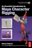
Joint Placement Workflow.
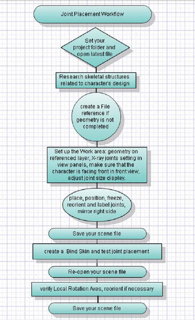
A skeletal structure is the support system for our bodies, and the same type of structure is needed for our digital characters. This structure is built in Maya using joints. Joints are connected to each other visually with bones, but bones do not really exist in Maya. They are simply a visual connection from one joint to the next. If you select a bone, you are actually selecting the joint above that bone in the hierarchy.
As joints are created, each subsequent joint is automatically connected as part of a hierarchy (unless you hit enter which ends the joint chain). This hierarchical system looks much like your family tree. The main difference is that there are only single parents in the Maya environment. While a joint can have many children, the children, however, can only have one parent. When you create two joints, the first joint is considered the parent and the second joint is considered the child of that parent. Each additional joint created becomes a child to the preceding joint. A series of connected joints is called a joint chain.

The hierarchy of a joint chain as seen in the Hypergraph.
![]()
The hierarchical system is present in Maya in other ways as well, not just with the joint chains. For example, when objects are grouped together, the group node that is created becomes the parent of all the objects in that group.
Before creating your joint chains, your character geometry should be as finished as possible. It is unnecessary to complete fine details in the geometry, but the main proportions of the character should be in place before beginning the joint placement process. If modeling with polygons, it is important not to smooth the finished model at this point in the rigging process as this will create extra geometry which will slow down the entire process of rigging and skinning.
When placing joints in your character’s geometry, it is important to study the physical shape of the character that you will be rigging. Depending on the type of character design for which you are creating controls, the first place to start would be to research the skeletal structure to ensure proper joint placement. For a biped character, this is a simple process since you are sitting in the best research available, which is your own skeleton. If you need to know how something moves or bends, you simply have to look at yourself.
If the character is a creature or something that may not exist in real life, it sometimes takes multiple existing animal parts to create a skeletal structure that may work for the creature that you are setting up. For example, a dragon is part reptile and bird, so you may want to study the skeletal structures of both reptiles and birds in order to create a basis for the dragon.
When you are placing joints in your character, think about each appendage as an individual joint chain. Create separate chains for each leg, arm, finger, torso, and head. These will all be connected into a single skeletal structure. You can also add chains for other body parts such as ears, tails, or antennae. You can even add joints and joint chains for articles of clothing or props, such as neckties or skirts, for better control when animating.

Frog Ballerina by Sarah Pitz.
Many times during the production process, the geometry for a character is not finished when it is time to begin the rigging process. Perhaps the textures are not completed or the blend shapes have not been modeled yet. In my classroom, the students have only 10 short weeks to not only learn and create a character, but also to animate their character. Once their character geometry is finished, we begin the rigging process in class, while outside of class they work on creating their textures and blend shapes. Because of the overlapping workflow, file referencing is utilized so that the latest version of the character model can easily be updated in the rig file.

Create Reference can be found under the File menu.
Creating a file reference does not actually make the file data PART OF the current scene. Referencing files only points Maya to a different file by creating a path and saving the path information. When your current scene file is saved, it is NOT including any data from the referenced file. It just tells Maya where to look when you open the file again. This reference can easily be removed or replaced as you are working. It can even be imported into the scene so that it eventually does become part of the scene file. File referencing can be used during the creation of assets (we’ll be using it during rigging and skinning), but it can also be used when animating.
If your character model scene file is large (2000 KB+), your rig scene files can be VERY SMALL in size, sometimes under 100 KB, if file referencing is used. This can be helpful if your disk space is limited and you are following the practice of saving versions of your files as you work. Instead of resaving the geometry every time you save, the only thing Maya is saving is the rig information.
To create a referenced file, open a new scene in Maya and go to [File > Create Reference – option box] In the option box under “Name Clash Options” make a check in the box next to “Use Namespaces.” This will ensure that the names of the nodes of the referenced file will not conflict with any that already exist in the current file. This is extremely important when referencing in several characters for animation. It is good to get in the habit of using namespaces. Maya will use a colon (:) in front of the node name to signify that the node is from another file. The default setting is to use the file name.
So, if you are referencing a file named “model.mb” and there is a node called “Left_Arm”, the referenced name will look like “model:Left_Arm”. If you set “Resolve all nodes with this string”, you are able to type something instead of using the lengthy name of a file (I suggest using this option and typing in your character’s name as the string).

The Create Reference options window.
Changing the Referenced File [File > Reference Editor]
If you make changes to your model and need to replace the referenced file, go to [File > Reference Editor…]. A dialog box will appear. Click on the file name to highlight it, then go to [Reference > Replace Reference]. This will open a dialog box that will allow you to browse for a new file. This will temporarily remove the reference from your scene, and then reload the new referenced file into the scene. By clicking [Reference > Remove Reference], you can PERMANENTLY remove the reference from your scene. By clicking [File > Import Objects from Reference], you can PERMANENTLY import the reference file into your scene. Be sure to delete history, once the objects are imported.

Create Reference can be found under the File menu.

The Reference Editor.

Replace Reference and Remove Reference can be found in the Reference Editor under the Reference menu.

Import Objects from Reference can be found in the Reference Editor under the File menu.
Before placing joints, make sure your character is facing front in the front view and in the top view, he should be facing down. This may sound obvious to some, but it is my experience that some students do not pay attention to the direction their character is facing. The tools in Maya were created with the assumption that the character is facing forward in the front view or in other words, toward the positive Z axis in 3D space. If for some reason, your character is not facing forward in the front view panel, you will need to rotate the geometry. You will need to make a group of your geometry if your character is made up of multiple pieces of geometry before being able to rotate them together.

Proper Character Placement for rigging.
The scale of your character is another important consideration. One square on the Maya grid is 1 cm by default. I have had students model their entire character to fit inside a single 1 cm grid square. Many of the tools used in Maya are based off of mathematical calculations. The problem with keeping your character so small is that these tools must calculate results using fractions in the thousandths or smaller. This creates a greater margin for error. My general rule is to keep the character arm span the width of the entire grid in the perspective window, at a minimum. If, for some reason, your character does not have an arm span that is the width of the perspective window grid, you will need to scale the geometry. Again, you will need to make a group of your geometry if your character is made up of multiple pieces of geometry before being able to scale them together. (If you had to group them for rotational purposes, you can scale the same group, another group is not necessary.)
![]()
DO NOT parent geometry pieces to other geometry pieces unless you have done so to create the blend shapes for the face. This causes double transformations after the skinning process.
Remember that when your character is facing you, his left side is your right side. This is important so that as you label all of your joints, you label the left and right sides correctly. Make sure to label all joints as this will make an organized and clean workflow and save time later. As you work, save versions of your work and save often.

The image of the character on the left looks similar in scale to the image of the character on the right. However, on closer look, the character on the left is actually the scale of the image in the middle. Make sure that your character is not too small, as it will cause problems with some tools and when animating.
When using a tool in Maya, always open the option box and reset the tool when using it for the first time that day. This ensures that the tool is working appropriately and is not based on the tool settings when it was last used.
It is a good idea to place the geometry for your character on a layer as discussed earlier. Set the layer to reference, so that you are unable to select the geometry by mistake when working. I recommend working with shading options set to X-Ray Joints (NEW IN MAYA 2008) so that you can still see your joints through your geometry. This is a personal preference, as others like working in wireframe.

Shading > X-Ray Joints.
The Joint Tool [Skeleton > Joint Tool]
The joint tool allows you to create joints by clicking on a grid. For this reason, you should always use the orthographic view panel (front, side, or top) when placing your joints. You can create a joint by moving your mouse cursor where you would like to position the joint and clicking with the LMB (left mouse button). A single joint appears as a circle with a crosshair in the center. A new joint is created every time you click the mouse. Subsequent joints are connected with bones, which look like a triangle with a line down the center pointing toward the new joint. To complete a chain of joints, simply hit the enter key on your keyboard. If you would like to create another chain, select the joint tool again by pressing the (y) key.

The Joint tool can be found in the Animation menu set (F2) on the keyboard under the Skeleton menu.
Two joints are connected visually with a bone.
Remember, a bone doesn’t really exist in Maya. It is simply a visual connection of one joint to the next.
You will notice that the closer you click the joints to each other, the smaller the joints appear. The further away the joints are from each other, the larger the joints appear. This can cause visual clutter in your scene file. This setting can be changed by opening the option box on the tool and changing the long bone radius to 0.5000. By changing the long bone radius to equal the short bone radius, all of the joints will be created as the same display size.

The long bone radius changes the size of the joint based on the distance it is from the following joint. Changing the long bone radius to 0.5 will prevent this.
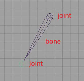
Display Size [Display > Animation > Joint Size…]
As you are drawing your joints, you might notice that they are small or large compared to the size of your character model. You can change the display size of the joints in order to see what you are doing more clearly. First, you may want to click out a few joints in one of the orthographic view panels. Then after opening in the joint display scale window, you can enter any numeric value or use the adjustable slider to interactively change the size of the joints.
Adjusting the display size of the joint will not affect how the joint works. You will notice that the position of the center point of the joint does not change regardless of the display size.
Joint Size options.
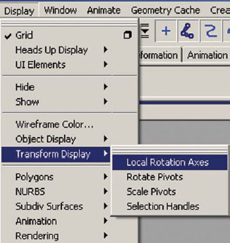
Local Rotational Axes [Display > Transform Display > Local Rotation Axes]
To understand local rotation axis, it is important to understand the 3D coordinate system and the differences between world space, object space, and local space. It’s time to think back to math class when you were first introduced to the Cartesian coordinate system. In the Cartesian coordinate system there are three intersecting perpendicular lines called axes. A point in the coordinate system is defined by three real numbers (an infinite decimal representation) and each number reveals the position of the point on each axis, X Y Z. The point of their intersection is referred to as the origin, and it is at the position of 0 0 0.
In Maya, we use a right-handed Cartesian coordinate system, where the X axis points left to right on your screen, the Y axis points up and down, and the Z axis points forward and backward. This coordinate system is considered world space.
If you create an object in Maya, such as a sphere, it is placed in world space at the origin. Imagine the XYZ axes lines sticking to the sphere.
Now imagine the sphere is moved away from the world space origin and rotated. The XYZ axes of the object (sphere) would be pointing in a different direction and no longer aligning with the world. This coordinate system is referred to as object space. The origin is at the object’s pivot point (currently at the center of the sphere), and its axes are rotated with the object. The origin can be moved by using the move pivot mode (select the move tool (w) and then press the (insert) key). Object space changes for each object in Maya, based on its rotation and translation values.

The Cartesian coordinate system and its point of origin.

A sphere that has been created at the origin and is in World space.
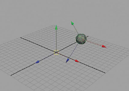
A sphere that has been moved from the origin and rotated shows a different coordinate system called Object space.
If the object’s transformations are frozen, the axes will return to align with world space, but the origin remains where it is currently located, still in Object space.
If an object is the child of another, and its parent is transformed, the object uses the origin and axes of its parent for its position in local space. This is especially important for translation values, as you can move an object based on its object, local, or world space, and it is particularly noticeable if the object has been rotated separate from its parent.

A sphere (left) that has been moved from the origin and rotated with its parent shows a different coordinate system called Object space. The same sphere (right) showing Local space.
The local rotation axis is a separate coordinate system for joints. The local rotation axis of a joint is determined by the position of its child. If a joint does not have a child, its local rotation axis aligns with world space. If a joint has a child, by default its X axis points toward that child and the Y axis will point upward (or as close to up as it can possibly go, based on its relationship to the X axis). We do have to be concerned when the joint chain is vertical or semi-vertical, because the X axis points toward up or down (depending on the direction of the children), therefore the Y axis cannot point up at the same time. Maya will arbitrarily point the Y in any direction, and the joint chain does not have the same local rotation axis throughout.

Local rotation axis set to XYZ on a vertical joint chain, where the axis does not line up from one joint to the next.
When do you worry about the local rotation axis? To ensure that joints rotate uniformly and predictably when using IK (inverse kinematics will be covered in Chapter 6), any joint chain created should be oriented properly for IK. This means that the X axis should be pointing toward the child joint, and the Y and Z axis are the same throughout the chain. This ensures that the IK tools will work as the creators defined them to do so.
However, to ensure that joints rotate correctly using FK, (forward kinematics will also be covered in Chapter 6) the joint orientation must align closely to world space. For the arms, we can achieve this alignment when drawing out the joints, but for the spine, neck, and head, we will run into trouble (and for the ankles and feet, but we won’t be setting up FK in the legs for this rig). It is impossible to have the X and Y axis pointing in the same direction. This means that the Y axis should be pointing toward the child (up in the spine), and the Z axis should be pointing forward. To solve this problem, we create multiple joint chains for the different types of control systems needed, and switch between the two. We must reorient the FK chain to match world axis.

A spine chain prepared for Forward Kinematic control.
![]()
The last joint of any chain will not rotate and therefore the local rotation axis position does not matter for that joint.
Placing joints with orientation set to XYZ will always ensure the X axis points toward the child joint, but the direction of the YZ axis depends on the direction of the child joint, especially in vertical or semi-vertical chains. If the X axis is going up or down, then the Y axis is unable to do so as well. This confuses Maya and it’s not sure which direction to place the Y. Sometimes the YZ axes will be flipped in different directions. You will need to ensure that they are all pointing in the same direction so that the joints are aligned. To solve this unpredictable behavior, change the tool settings whenever creating joint chains for a biped character so that the joints are created with the orientation XZY and second axis orientation is +Z. (You could also reorient the joints after positioning them.)

A spine chain prepared for Inverse Kinematic control.
There are two ways to check the directions of the local rotation axes in your character’s joints:
1. Object mode: Select the joints you would like to display then go to [Display > Transform Display > Local Rotation Axes].
2. Component mode: Press (F8) on the keyboard to change to component mode or click on the component mode button. In the selection mask tool bar, place your cursor over the “?” button, RMB (right mouse button) click and hold, and then select Local Rotation Axes from pop-up menu that appears. In the perspective view panel, select the root of the chain you would like to display. Every joint in the selected hierarchy will display its own local rotation axis.
Displaying the Local Rotation Axes in Object Mode requires that each and every joint be selected.

Displaying the Local Rotation Axes in Component Mode requires that the top of the hierarchy be selected to see all of the Local Rotation Axes for that hierarchy.
Placing Joints
The joint transforms around the position of its center point. It is important to make sure that the joint is positioned in the exact place in order to control your character appropriately. As you begin to place joints, you may find that you have misplaced them in the process. You can [Edit > Undo] or press (z) on the keyboard and continue to recreate joints. While placing joints, you can click and hold the LMB, then drag the joint into the correct position.
Repositioning Joints
Once you place joints in one of the orthographic views, such as the side, front, or top, it is important to look at the perspective view panel to ensure correct and proper placement in 3D space. You may notice that the joints are not in the proper place and need to be repositioned. Repositioning the joints can be done by using the move, rotate, or scale tools.
Moving Joints (AKA – translating joints)
The move tool – keyboard shortcut (w) – will move the selected joint and any joints below it in the hierarchy. If the selected joint is the first chain in the hierarchy, then the entire chain will move. To move an individual joint, you must first select the move tool by pressing (w) and then press the (insert) key on the keyboard to toggle into the move pivot mode. The move pivot mode will allow you to move only the selected joint.

Moving a joint into place will also move any joints below it in the hierarchy (left), unless the move pivot mode is toggled on by pressing the Insert key on the keyboard (right).
![]()
If you use the move tool to move joints into position, the local rotation axis of the translated joint stays at the orientation in which it was created. This means that it will no longer be aligned with the child joint. If you must move a joint, make sure to reorient the joints.
Rotating and Scaling Joints
The rotate tool – keyboard shortcut (e) – and the scale tool – keyboard shortcut (r) – can be used to rotate or scale a joint into place. If a joint is rotated or scaled, you MUST freeze transformations on the joint to reset rotation values back to zero and scale values back to one. To do this, select the top joint of the hierarchy and go to [Modify > Freeze Transformations – option box].
![]()
Translate values will not freeze on joints. There will always be a value in one or all translation channels for a joint. Maya must have translation values for a joint so that it knows where that joint is located in world space or in relation to its parent joint.
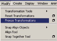
Rotating or scaling joints into place requires the Freeze Transformation command to reset the values.
Reorienting Joints [Skeleton > Orient Joint – option box]
After you have finished placing your joints, I recommend displaying your local rotational axes and reorienting them if necessary. There will be special circumstances (such as the thumb joints) that will require the need for manually rotating the local rotational axis into position. Also, if you used the move tool reposition the joints into place, the local rotational axis of the translated joint is no longer aligned with its child. If you must move a joint, make sure to reorient them.
![]()
It is not necessary to reorient a joint if the entire joint chain was moved.
![]()
Warning signs for non-zero rotations appear during the reorientation process if the joint’s transformations have not been frozen.
Remember, if you rotated a joint into place, you must first freeze transformation [Modify > Freeze Transformations] on that joint before you reorient. Avoiding this step will result in an error message during some commands with a Hot Pink Alert: Joint has non-zero rotations, and sometimes the joint will be skipped when trying to reorient.
To reorient a joint or joint chain, select the joint in object mode OR select the axis in component mode and go to [Skeleton > Orient Joint – option box]. UNCHECK Hierarchy to orient only one joint, or CHECK Hierarchy to orient that joint and ALL child joints (this option only affects the entire hierarchy in object mode, in component mode, you must shift + select each joint axis that needs to be reoriented). Choose the orient joint options and then choose the second axis orientation. Click APPLY. If you are in component mode, make sure to press (F8) to change back to object mode or click on the component mode button in the Status Line.
If necessary, you can manually rotate the local rotational axis into position when you are in component mode. Select the desired axis with the rotate tool by pressing the (e) and adjust in place. When finished, press (F8) to change back to object mode or click on the component mode button.
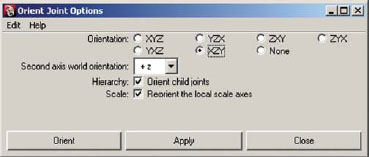
Orient joint option box.

Manual rotation of a joint’s Local Rotation Axis is possible for fine tuning joint rotation.
You can also change the rotational axis by MEL (Maya Embedded Language) command. In component mode, select the desired axis and enter in the Command Line the following command (change the numbers and axis as necessary) and press enter:
rotate -r -os 0 180 0 (these particular values will rotate the axis exactly 180 degrees in Y)
where -r stands for relative, -os stands for object Space, 0 180 0 are values of X Y Z coordinates.

A MEL command can be used for precise rotation of the axis.
Former Student Spotlight: Sean Danyi
Creating a well rounded skill set will not only help you by opening more venues to display your skill, but it will allow you to focus more readily on and augment your strengths. It is incredibly important to not only understand how to make your character move, but what is making him move that way. If you know beforehand what motions you will need for a particular shot, you can make sure that your setup can accommodate anything you will need.
Case in point: I am, by nature, an animator, so my points will come from this perspective. In school I focused primarily on developing my tradition and digital animation techniques. However, I also knew that it would be absolutely critical for me to gain at least a moderate skill set in rigging. Though daunting at first, this paid off for me as I applied for my (now) current job.
After several weeks of emails, phone calls and interviews, they gave me one final task to accomplish. I had to take a character the studio gave me, and perform three animation cycles for them. However, the character they supplied me with was far too limited to create any kind of believable motion, which they even warned me about. So, I took the first day, and nearly dismantled the entire thing, and rebuilt him with all the abilities I knew he was going to require. This simple step allowed me to then focus on my strengths in animating, and not fighting with a limited rig.
I would suggest creating a very simple character, with a very specific task, and attempt to rig him specifically for that. If he needs to flip, make him flip. If he needs to pick something up, rig him up to do so. Try to solve one problem at a time. The better equipped you can be before going to your first gig, the better. As animators, we are in essence actors. And rigging can be likened to singing. You don’t have to be able to sing to get a part, but if you can, there are many more unique opportunities out there for you.
Sean Danyi graduated from the Savannah College of Art and Design (SCAD) in 2005 with a BFA in Animation. In 2004, he completed an internship with Will Vinton Studios where he worked in collaboration with seven other interns to create the short film, “Hellp!” He is currently employed as an animator with Human Head Studios in Madison, WI.

Little Billy by Sean Danyi (2003).
5.1 A skeletal structure is built in Maya using joint hierarchies.
5.2 Bones are visual connections from one joint to the next but do not physically exist in the Maya scene file.
5.3 The main proportions of the character geometry should be in place before beginning the skeletal structure.
5.4 If a character is made of polygons, it is important not to smooth the geometry at this point, as it adds unnecessary problems later in the skinning process.
5.5 A character’s skeletal structure should be based on reality. Research is crucial for proper motion. Sometimes it is necessary to combine skeletal structures from multiple animals in order to create a skeleton that works for your character.
5.6 Each appendage should be considered as a separate control system, so separate joint chains should be created for each leg, arm, finger, torso, head, ears, or tails.
5.7 File referencing is a tool that can be used to expedite workflow. File referencing provides the ability to overlap areas of the production pipeline.
5.8 Files that are referenced into another scene file are not physically part of current scene. Instead, a path is made that points to the referenced scene file so that Maya can display it.
5.9 When using file referencing, make sure to utilize the name clash options so that multiple nodes with the same name are not confused.
5.10 Files that are referenced can be removed, replaced, or even imported into the current scene file.
5.11 Remember that when your character is facing you, his left side is your right side. This is important so that you label left and right sides correctly.
5.12 Make sure to always open the tool option box to reset the tool before using it for the first time every day.
5.13 Geometry should be placed on its own layer so that it can be referenced. This makes it more difficult to accidentally select the geometry, making it easier to work with joints.
5.14 Using X-Ray Joints in the shading options of each view panel provides the ability to see the joints through your geometry.
5.15 Joints can only be created on a grid, and for this reason, joints are placed only in orthographic view panels.
5.16 Joints can be displayed at different sizes without affecting their functionality.
5.17 Maya uses a right-handed Cartesian coordinate system in order to define the position of objects in world space, where the X axis points left to right, the Y axis points up and down, and the Z axis points forward and backward.
5.18 Object space is a coordinate system based on the translation and rotation of a particular object. Each object exists in its own object space.
5.19 Local space is a coordinate system that determines an object’s position based on its position and how it relates to the position of its parent.
5.20 Local rotation axis is a separate coordinate system that applies to joints. The local rotation axis of a joint is determined by the position of its child.
5.21 The default setting of the local rotation axis is XYZ, where X points to the child joint and Y points in an upward direction.
5.22 The local rotation axis for joints being controlled by an IK chain must have X pointing toward the child.
5.23 The local rotation axis for joints being controlled by FK must have the local rotation axis matching closely to world space.
5.24 You can display the local rotational axes in object mode or component mode.
5.25 If a mistake is made when positioning joints, simply undo the mistake and continue with the placement.
5.26 Joints can be moved, rotated, or scaled into place. If rotated or scaled, joint transformations must be frozen. If moved, joint orientation must be reoriented.
5.27 A warning sign is displayed when reorienting if a joint’s rotations are not frozen at zero.
5.28 Manual rotation of the local rotational axis must sometimes occur. This can be accomplished in component mode using the rotate tool.
5.29 The following MEL command can be used for precise rotations of the local rotation axis: rotate -r -os 0 180 0.
Assignments: Joint Placement in a Character
![]()
Remember, your body is your best reference for joint placement. If you are unsure where a joint should be placed, stand in front of a mirror for observation and put your hand on the area in question to feel how your skeleton moves.
Assignment 5.1: Creating a Spine, Neck, and Head Skeleton
Set up your work environment by doing the following:
1. Open Maya and set your project.
a. From your computer’s desktop, go to [Start > Programs] and select Maya.
b. Once Maya is open go to [File > Project > Set…] and browse to your project folder then click OK.
2. Create a reference to your last saved file:
a. Go to [File > Create Reference] and select 04_asgn02.ma. This will insure that your model will be updated easily if you are still working on modeling, texturing, or blend shapes.
3. Set all four view panels to X-Ray Joints mode. This will allow you to see your joints easily and still be able to see the volume of your geometry.
a. In the top, front, side, and perspective view panels, go to [Shading > X-Ray Joints].

Setting all four view panels to X-Ray Joints mode.
4. Make sure that your geometry layer is set to R for reference. This ensures that you are unable to select the geometry by mistake when working.
5. Select the [Skeleton > Joint Tool – option box], or double click on the icon on the shelf. In the option window, click on RESET TOOL, then set the following:
a. change the orientation to XZY.
b. change the second axis world orientation to +Z.
c. click close.

The Joint tool option settings.
6. Select [Skeleton > Joint Tool] and click out a few joints in the orthographic view near your character. Go to [Display > Animation > Joint Size] and adjust the slider to adjust the size of the joint. Select the joints using the select tool – by pressing (q), and hit the delete key, as these joints were only created to set the joint display size.

Adjusting the display size of the joints.
![]()
If the textures become distracting, press the (5) key to turn off hardware texturing.
7. Create the spine joint hierarchy by doing the following:
a. In the FRONT orthographic view, place 6 joints for the spine as follows:
Click the first joint in the waist area, hold down the shift key and click the second joint just above the first, and continue to the shoulder area. One joint is placed at the base of the rib cage, and the sixth joint is placed in the center of the shoulders. Hit enter to finish the chain. (It is important to keep the joints in the spine straight, even if your character has an exaggerated posture or curved back. Holding down the shift key as you click your joints ensures that they are drawn in a straight line.)
b. Rename these joints spine1, spine2, spine3, spine4, spine5, and spine6.
![]()
You can rename the joints easily by selecting joint1 and opening [Modify > Search and Replace Names…] then enter the following: Search for: joint Replace with: spine.
c. In the SIDE orthographic view, select the spine1 joint and adjust the position in the torso geometry if necessary.

Positioning and renaming the spine joints.
d. In the SIDE view, place 1 joint below the spine1 joint, rename this joint pelvis.

Placing the pelvis joint.
1. Create the neck and head joint hierarchy by doing the following:
a. Select [Skeleton > Joint Tool]
b. In the SIDE orthographic view place 3 joints for the neck and head as follows:
Click the first joint in the center of the neck, hold down the shift key and click the second joint at the base of the head. Keep the shift key held down and click the third joint at the top of the head. Hit enter to finish the chain.
c. Double-click on each joint in the outliner to rename them as follows: neck, head, and headTip.

Placing and renaming the neck and head joints.
![]()
If your character has a mouth, you can control the mouth opening and closing with joints instead of blend shapes. Some prefer this control as it looks more natural, since our mouth opens from the rotation of our jaw.
2. Create the jaw joint hierarchy by doing the following (optional):
a. Select the joint tool by pressing (y) on the keyboard.
b. In the SIDE orthographic view, click FIRST on the head joint to begin a new chain that is branching from the head joint. Place 2 joints for the jaw as follows:
Click the first joint at the base of the ear where the jaw hinges and the second joint in the chin. Hit enter to finish the chain.
c. Rename these joints jaw and chin.
3. Create tongue joint hierarchy by doing the following (optional):
a. Select the joint tool by pressing (y) on the keyboard.
b. In the SIDE orthographic view, click FIRST on the jaw joint to begin a new chain. Then place 3 joints for the tongue as follows:
Click the first joint at the back of the tongue, the next in the middle, and the third on the tip. Hit enter to finish the chain.

Placing and renaming the jaw joints.
c. Rename these joints tongue1, tongue2, and tongueTip.

Placing and renaming the tongue joints.
4. Save your scene file. Name your scene 05_asgn01.ma.
![]()
The number of joints is suggested and what I would consider the minimum amount needed. You can always add more joints for more flexibility or necessity. For example, if your character has a big nose, you may want to add a two or three joint chain stemming from the head joint so that you can control the nose movement. A blend shape can also be used for the nose movement. In summary, it is better to have a few extra joints than not enough at all.
Assignment 5.2: Creating an Arm and Hand Skeleton
1. Continue working on scene 05_asgn01.ma.
2. Create the arm joint hierarchy by doing the following:
a. Select [Skeleton > Joint Tool]. Keep the orientation to XZY and the second axis world orientation to +Z.
b. In the FRONT orthographic view place 5 joints for the arm as follows:
Click the first joint in the shoulder.
![]()
The shoulder is probably the toughest joint to position properly. Placing it too far into the arm geometry makes your arm bend bizarrely at the bicep instead of the shoulder. Placing it too far into your body geometry concaves your torso and breaks the shoulder. After we place all of our joints, we will test the position to see how things look when they bend. Fine tuning the position of the shoulder will occur at that time.
c. While holding down the shift key click the second joint in the elbow, the third joint in the forearm, the fourth joint in the wrist, and the fifth joint in the palm of the hand. Hit enter to finish the chain. Holding the shift key ensures that the arm is drawn in a straight line.
d. Rename these joints shoulder, elbow, forearm, wrist, and palm.

Placing and renaming the arm joints.
e. In the TOP orthographic view, select the shoulder joint and adjust the position in the arm geometry if necessary. Remember, it is not necessary to reorient a chain if it is moved in its entirety. (Our arms do not actually have a forearm joint. What we do have is a radius and an ulna that allows rotation of the forearm. The forearm joint will act as the radius and ulna, which will allow for rotation of the forearm without rotation of the elbow.)

Repositioning the arm joints.
f. In the FRONT orthographic view place 2 joints for the clavicle.
Click the first near the spine, at the base of the clavicle. While holding down the (v) key, click the second joint in the existing shoulder joint. The (v) key turns the point snap, which will snap the new joint into the same position as the existing shoulder joint. Hit enter to finish the chain.
g. Rename these joints left_clavicle and left_clavicleTip.

Placing and renaming the clavicle joints.
h. In the PERSPECTIVE view, check for proper alignment. Select the left_clavicle joint, and with the move pivot tool, translate the joint to the front of the geometry. (To get to the move pivot tool, press (w) then hit the insert key.)
i. Since we moved the joint we must reorient. With the clavicle joint selected, go to [Skeleton > Orient Joint – option box]. Choose orientation: XZY and second world orientation: +Z then click ORIENT.

Repositioning and reorienting the clavicle joints.
![]()
After creating the hands, we will mirror the left arm to create the right arm.
3. Create the hand joint hierarchy by doing the following:
a. Select [Skeleton > Joint Tool]
![]()
While it is not necessary to have four fingers and a thumb for your character, I recommend a minimum of a thumb and middle finger, or mitt. Since our hands are such an expressive part of our body, it is important to be able to gesture with them.
b. In the TOP orthographic view, click FIRST on the palm joint to begin a new chain for a finger that is branching from the palm joint. Place 4 joints for the middle finger, placing 1 at each knuckle (observe your own hand for clues about joint placement) and one on the tip of the finger (the last joint is placed to allow the prior joint to bend, the last joint never rotates). Hit enter to finish the chain.
c. Rename the finger joints as follows: middle1, middle2, middle3, middleTip (You can rename the joints easily by selecting joint1 and opening [Modify > Search and Replace Names…] then enter the following: Search for: joint Replace with: middle, and then relabel middle4 as middleTip).
d. Repeat this process for the index and ring finger, if your character has them. Press the (y) key to choose our last tool – the joint tool. Click FIRST on the palm joint, and then place 4 joints for the index finger. Hit enter to finish the chain.
Rename the finger joints as follows: index1, index2, index3, indexTip (You can rename the joints easily by selecting joint1 and opening [Modify > Search and Replace Names…] then enter the following: Search for: joint Replace with: index, and then relabel index4 as indexTip).
e. Press the (y) key to choose our last tool, click FIRST on the palm joint, and then place 4 joints for the ring finger. Hit enter to finish the chain. Rename the finger joints as follows: ring1, ring2, ring3, ringTip (You can rename the joints easily by selecting joint1 and opening [Modify > Search and Replace Names…] then enter the following: Search for: joint Replace with: ring, and then relabel ring4 as indexTip).

Placing and renaming the middle, index, and ring finger joints.
![]()
The pinky and thumb joints will be a little different than the index and ring fingers in that they will start down near the base of the hand at the wrist. You are not stemming the pinky finger or thumb from the palm because you want them to work independently of the three middle fingers, allowing you to pose the hand into a cupped position.
f. Press the (y) key to choose our last tool, click FIRST on the wrist joint, and then place 5 joints for the pinky finger as follows: place 1 joint for the pinky side of the palm as well as 4 joints for the pinky finger. Hit enter to finish the chain.
Rename the finger joints as follows: pinkyPalm, pinky1, pinky2, pinky3, pinkyTip.
Press the (y) key to choose our last tool, click FIRST on the wrist joint, and then place 4 joints for the thumb as follows: place 1 joint for the thumb side of the palm as well as 3 joints for the thumb. Hit enter to finish the chain. Rename the finger joints as follows: thumbPalm, thumb1, thumb2, thumbTip.

Placing and renaming the thumb and pinky finger joints.
g. In the PERSPECTIVE view, move or rotate the finger joints so that they line up on the top edge of the geometry. By doing this, your character’s geometry will bend and deform more realistically. The first knuckle of each finger should be set back slightly in the hand. Look at your own hand for reference and notice where the knuckles are.

Repositioning the finger joints in the perspective window.
![]()
DO NOT MOVE THE PALM JOINT. It is important that the palm stay in line with the wrist so that the hand works predictably with the control rig.
h. If you rotated any of the joints, you should freeze transformations on the rotations. Select the wrist joint and go to [Modify > Freeze Transformations]. Don’t forget to open the option box and reset the options to default settings before applying.
i. If you moved any joints, make sure to reorient the joints in the hand once they have all been moved into place. Select the wrist joint and go to [Skeleton > Orient Joint – option box]. Choose orientation: XZY and second world orientation: +Z then click ORIENT.

Reorienting the joints in the hand.
j. Rename your arm chain to include left_ prefix by selecting the shoulder joint, then go to [Modify > Prefix Hierarchy Names…]. Enter left_ in the text field and click OK.
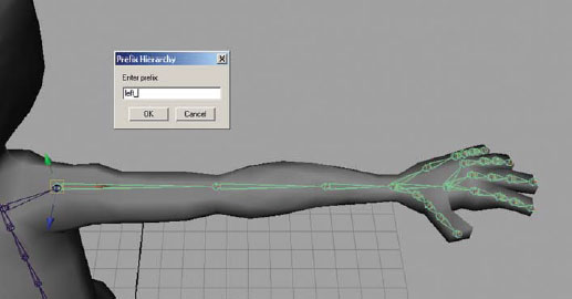
Adding the left prefix to the arm chain.
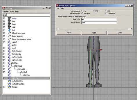
k. Mirror the left arm to create the right arm by selecting the left_shoulder joint, then go to [Skeleton > Mirror Joint – option box] and enter the following:
Mirror Across: choose YZ axis (Mirroring across the YZ axis will mirror from left to right – on the X axis. This can be slightly confusing at first. An easier way to think about the direction is to establish a line on the missing axis (X in this case) and that is the direction of your mirrored skeleton. Another way is to imagine a flat plane created by the stated axis YZ – up and down PLUS front to back (hey … imagine a mirror … like a full length one that you have on your wall). THE mirrored skeleton is the reflection on that axis (or in that mirror).)

Establishing the mirror direction as a reflection. Mirroring on the XY (left), mirroring on the YZ (middle), and mirroring on the XZ (right).
Mirror Function: choose behavior (Mirroring your joints with “behavior” allows for the animator to choose both elbows and rotate them simultaneously in the same direction. This usually means that the X axis is rotated 180 degrees, pointing away from the child joint. Mirroring your joints with orientation keeps the X axis pointing toward the child joint. Either will give you the results needed, but behavior seems to be most popular with animators because it speeds up the posing process when animating in FK.)
Replacement names for duplicated joints:
Search For: enter left
Replace With: enter right
Then click mirror to execute the command.
l. Mirror the left clavicle to create the right clavicle by selecting the left_clavicle joint, then go to [Skeleton > Mirror Joint] or hit the (g) key to repeat the last command.
4. Save your scene file. Name your scene 05_asgn02.ma.

The mirror joint options.
Assignment 5.3: Creating a Leg Skeleton
1. Continue working on scene 05_asgn02.ma.
2. Create the leg joint hierarchy by doing the following:
a. Select [Skeleton > Joint Tool]. Keep the orientation to XZY and the second axis world orientation to +Z.
b. In the SIDE orthographic view, place 5 joints for the leg as follows:
Click the first joint in the hip.
c. Click the second joint in the knee, the third joint in the ankle, the fourth joint in the ball of the foot, and while holding down the shift key, click the fifth joint at the tip of the toe. Hit enter to finish the chain. Holding the shift key ensures that the toe is drawn in a straight line from the ball. (If your character’s leg geometry is bent, be sure to draw the knee in a bent position. However, be careful not to overdo the bend as this will cause hyperextension of the knee when the leg is straightened. For this reason, if your character’s leg geometry is straight, make sure to draw the knee and ankle straight down from the hip. Holding the shift key ensures that the joints are drawn straight.)
d. Rename these joints hip, knee, ankle, ball, and toe.

Placing and renaming the leg joints.
e. In the FRONT orthographic view, select the hip joint and move the joint chain along the X axis (the red arrow) into the left leg of your character’s geometry. Remember, it is not necessary to reorient a joint chain if it is moved in its entirety.

Repositioning the leg joints in the FRONT orthographic view panel.
![]() DO NOT move the knee or ankle out of alignment in the front view. The entire leg must be straight in the front view for predictable IK movement. If necessary, you can ROTATE the entire chain from the hip joint to align the leg. Remember to go to [Modify > Freeze Transformations] if rotations are used to position the joint chain.
DO NOT move the knee or ankle out of alignment in the front view. The entire leg must be straight in the front view for predictable IK movement. If necessary, you can ROTATE the entire chain from the hip joint to align the leg. Remember to go to [Modify > Freeze Transformations] if rotations are used to position the joint chain.
f. Rename your leg chain to include left_ prefix by selecting the hip joint, then go to [Modify > Prefix Hierarchy Names…]. Enter left_ in the text field and click OK.
g. Mirror the left hip to create the right hip by selecting the left_hip joint, then go to [Skeleton > Mirror Joint].
Mirroring the left leg to create the right leg.
3. Save your scene file. Name your scene 05_asgn03.ma.
Assignment 5.4: Test the Joint Placement
1. Continue working on scene 05_asgn03.ma.
2. Select all joints by going to [Edit > Select All By Type > Joints].
3. Make sure that your geometry layer is set to normal by clicking on the R until the box is empty so that you are able to add the geometry to the selection.
4. Hold down the shift key and click on the character geometry piece(s).
5. Create a test skin bind by going to [Skin > Bind Skin > Smooth Bind].
6. Return your geometry layer back to reference by setting the layer to R so that you are unable to select the geometry by mistake when testing the joints.
7. Select a shoulder joint and rotate it so that the arm is down. Check the movement on the elbows, the knees, and the hips. These areas are the most problematic. What we are looking for is proper joint placement and verification that the bending of the shoulder, elbow, knee, and hips provide natural deformation that holds the shape. Refer to the images below to verify what is acceptable, and what is not.
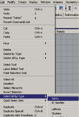
Selecting all of the joints.
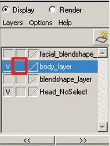
Changing the geometry layer to normal.

Creating a skin deformer.

Changing the geometry layer back to reference.
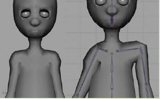
Good deformations on the character’s shoulders on the left, and bad deformations caused by improper joint positions on the character’s shoulders on the right. The right image shows two common problems. The left shoulder (right image) has a joint that is placed too far into the bicep. The right shoulder (right image) has a joint that is placed too far into the body.
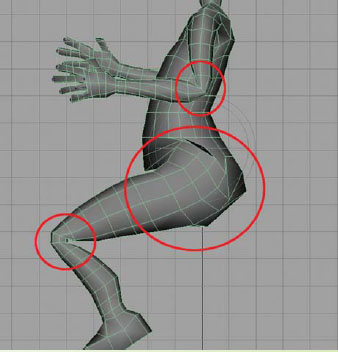
The area around the waist may look like it is cracking and indenting. This is not a joint placement issue, but rather, the skin deformer needs to be smoothed in this area (covered in Chapter 8). The elbows and the knees are pinching because there are not enough divisions in the geometry to make a smooth bend.

Think about the difference between a regular straw and a flexi-straw. A regular straw pinches when it bent (left). A flexi-straw can bend more smoothly because of the added divisions allowing it to bend (right).
![]()
If you move a joint and the geometry is pulled bizarrely or pushed into the body, note that this is NOT a joint placement problem. Any indentions and pulling of geometry can be fixed during the Paint Skin Weights process covered in Chapter 8.
8. DO NOT SAVE THE FILE.
9. If no changes are necessary, reopen the file 05_asgn03.ma, save the file as 05_asgn04.ma and continue with Assignment 5.5.
10. If changes are necessary, reopen the file 05_asgn03.ma, take your move pivot tool – press the (w) then press the insert key and move the joints ONLY on the X axis (the red line) to place them into a better position. Adjust the left side only.
Repositioning joints in the shoulder.
11. With the joint chain selected, reorient by going to [Skeleton > Orient Joint – option box]. Choose orientation: XZY and second world orientation: +Z then click ORIENT.
12. If there is a problem with the left arm or leg, then the right arm and leg will also need to be fixed. Simply delete the right chain in question (select in the outliner and hit the delete key) and select the left joint chain and go to [Skeleton > Mirror Joint] to re-mirror the right side.
13. If there is a problem with the geometry due to inadequate divisions, you must update the character model. Since your file is still referenced, you must open the referenced model file and make changes there by doing the following:
a. Delete the non-deformer history first by going to [Edit > Delete by Type > Non-Deformer History]. (This ensures that the blend shape deformer is not removed.)
b. Then add extra geometry in the troubled areas using the [Edit NURBS > Insert Isoparms] tool for NURBS surfaces (refer to Chapter 2 for more details on how to insert isoparms). Use the [Edit Mesh > Insert Edge Loop Tool] for Polygons.
c. Since the geometry has a Blend Shape deformer applied, be sure to [Blend Shape > Bake Topology to Targets]. (Refer to Chapter 3 for more details on how to add topology to your blend shapes.)
14. Save your scene file 05_asgn04.ma.
15. Follow the steps above until the proper movement is achieved.
![]()
There is a new tool in Maya 2008 called the Move Skinned Joints Tool. It provides the ability to reposition joints quickly while the character is still bound to the skin. This tool is helpful to promptly check to see if the new position will work for the skin deformer. Don’t forget to reorient the joint chain while the tool is still in use, and to [Skin > Detach Skin] the geometry when completed, if you use this tool to reposition the problem joints.
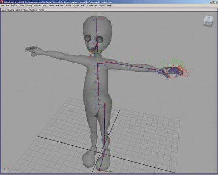
Assignment 5.5: Verifying the Joint Local Rotation Axis
Your joint local rotational axes should already be correct for your skeleton, assuming that you placed your joints correctly (with orientation: XZY and second world orientation: +Z), froze transformations when necessary (when you rotated or scaled joints into position), and reoriented them if they were moved after the original placement. The thumb joints are the only joints that will definitely need tweaking for their position. The wrist joints might need a slight adjustment, also.
It is a great idea to verify that all of the joint local rotational positions are correct before beginning to build your controls in Chapter 6.
1. Continue working on scene 05_asgn04.ma.
2. Let’s first evaluate the axes and determine if any need to be fixed.
a. Select all joints by going to [Edit > Select All By Type > Joints].
b. Then go to [Display > Transform Display > Local Rotation Axes].
c. The torso, neck, head, left arm, hand, and leg should have the X axis pointing toward the child and the Z axis coming forward.
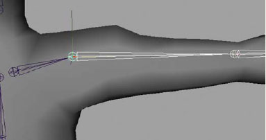
The proper Local Rotation Axis for the joints.
d. The right arm, hand, and leg should be mirrored on behavior, and therefore the X axis should be pointing away from the child and the Z axis pointing backward.

The proper Local Rotation Axis for the right arm and leg.
Remember, the last joint of any chain will not rotate and therefore the local rotation axis position does not matter for that joint.
3. If there is a problem with the orientation on the torso, neck, head, left arm, hand, or leg, simply select the top of the joint chain by opening the outliner [Window > Outliner] and choose the top joint, then reorient by going to [Skeleton > Orient Joint – option box]. Choose orientation: XZY and second world orientation: +Z then click ORIENT.
4. If there is a problem with the left arm, hand, or leg, then the right arm, hand, or leg will also need to be fixed. Simply delete the right chain in question (select in the outliner and hit the delete key) and select the left joint chain and go to [Skeleton > Mirror Joint] to re-mirror the right side.
5. Turn off the Local Rotation Axes Display as follows:
a. Select all joints by going to [Edit > Select All By Type > Joints].
b. Then go to [Display > Transform Display > Local Rotation Axes].
6. The wrist joints and the thumb joints will need to be adjusted manually as follows:
a. Select the left_wrist joint, then shift select the right_wrist joint.
b. Press (F8) on the keyboard to change to component mode or click on the component mode button. In the selection mask tool bar, LMB click on the points button to turn it off and RMB click and hold the “?” button and select Local Rotation Axes from the marking menu that appears.

Displaying the Local Rotation Axis in component mode.
c. Starting with the left thumb, use the selection tool – press (q) – to click on the thumb_palm axis. Holding down the shift key, click the thumb1 axis, and the thumb2 axis. Rotate – press (e) – the thumb_ palm, thumb1, and thumb2 axes so that the Y axis is intersecting the joint in the direction the bend will occur.

Rotating the thumb Local Rotation Axis into position.
d. Repeat this for the right thumb. On the right side, the Y axis comes out the underside of the thumb.
![]()
To visualize this, hold your hand in the same position that your character’s hand is modeled. Pick up a pen or pencil and IMAGINE – do not really do this – IMAGINE that pen or pencil being jabbed into your thumb knuckle and coming out of the other side. That pen would be the Y axis.

Visualizing the direction of the Y axis by using a pen.
7. In the TOP orthographic view, verify that the wrist local rotational axis is aligned straight with the graph. To do this, click on the wrist axis and select the rotate tool by pressing (e) on the keyboard. The inside of the tool should appear as a + and be even with the graph. If not, carefully rotate the Y axis (the green part of the rotate tool) until the + aligns with the graph.

Verifying that the wrist Local Rotation Axis is straight.
8. Save your scene file 05_asgn05.ma.
![]()
At any time you can go back and fine tune your joint orientations if necessary.
Assignment 5.6: Adding Additional Joint Chains for Clothing, Tails, Antennae, or Other Areas
With the techniques you have learned in this chapter, you can add additional joint chains for anything else on your character that needs control: neckties, ponytails, skirts, tails, antennae, or ears, etc. Just remember, any joint chains that are vertical and have FK control need the Y axis pointing toward the child joint. Any joint chains that are horizontal (front to back) and have FK control need the Z axis pointing toward the child joint (like a tail). Any joint chains that are horizontal (side to side) and have FK control need the X axis pointing toward the child joint. Any joint chains controlled by IK need to have the X axis pointing toward the child joint. If the control is created using Set Driven Key (like the fingers), it really doesn’t matter which axis points to the child, as long as the axes for the joints in the chain are consistently the same.