


Environmental requirements
This chapter addresses the environmental requirements for the IBM z13. It lists the dimensions, weights, power, and cooling requirements that are needed to plan for the installation of an z13, and what is required to upgrade to an IBM z BladeCenter Extension Model 004 (zBX Model 004).
There are several options for the physical installation of the server:
•Air or water cooling
•Installation on a raised floor or non-raised floor
•I/O and power cables exiting under the raised floor or off the top of the server frames
•Having a high-voltage DC power supply as an alternative to the usual AC power supply
For more information about physical planning, see IBM z13 Installation Manual for Physical Planning, GC28-6938 for the z13, and zBX Model 004 Installation Manuel for Physical Planning, GC27-2630 for the zBX Model 004.
This chapter includes the following sections:
10.1 z13 power and cooling
The z13 always is a two-frame system. The frames are shipped separately and are bolted together during the installation procedure. The z13 supports installation on a raised floor or non-raised floor. However, the z13 with the water-cooling feature must be installed on a raised floor because the water hoses must attach to the server from underneath the raised floor. Power and I/O cables also exit from the bottom of the server frames unless the Top Exit I/O Cabling feature code (FC 7942) or Top Exit Power feature code (FC 7901) is installed. These options allow I/O cables and power cables to exit from the top of the server into overhead cabling rails.
10.1.1 z13 new rear cover design for vectored air output
The new design of the rear door covers addresses data center airflow challenges. You can change the cover (door) fins orientation down or up, as shown in Figure 10-1. This design allows you to direct the hot air that is exhausted by z13 to avoid adversely affecting cooling of other systems on the hot aisle.

Figure 10-1 Rear cover vectored air output
The new rear doors are all the same part. In the installation planning meeting, you can decide in which orientation the IBM Service Support Representative (IBM SSR) should install the covers. For further planning information about the vectored orientation, see the IBM z13 Installation Manual for Physical Planning, GC28-6938 or ask your IBM SSR.
10.1.2 Power requirements and consumption
This section describes the power requirements and consumption for an z13.
Power requirements
The system operates with two fully redundant power supplies. One is in the front, and the other is in the rear of the Z frame. Each power supply has either one or two power cords. The number of power cords that are required depends on the system configuration. The total loss of one power supply has no impact on system operation.
Systems that have two power cords (one in the front and one in the rear) can be started with one power cord and continue to run.
The larger systems that have a minimum of four bulk power regulator (BPR) pairs that are installed must have four power cords installed. A system that has four power cords can be started with two power cords on the same power supply with sufficient power to keep the system running.
Power cords attach to either 3-phase, 50/60 Hz, 200 - 480 V AC power, or 380 - 520 V DC power.
The High-Voltage Direct Current power feature is an option for z13. It allows z13 to directly use the high voltage (HV) DC distribution. A direct HVDC data center power design can improve data center energy efficiency by removing the need for a DC to AC inversion step.
The z13 bulk power supplies have been modified to support HVDC, so the only difference in the included hardware to implement this option is the DC power cords. Because HVDC is a new technology, there are multiple proposed standards. The z13 supports both ground referenced and dual polarity HVDC supplies, such as +/-190 V, +/-260 V, and +380 V. Beyond the data center uninterruptible power supply and power distribution energy savings, a z13 that runs on HVDC power draws 1 - 3% less input power. HVDC does not change the number of power cords that a system requires.
For ancillary equipment, such as the Hardware Management Console (HMC), its display, and switch, extra single-phase outlets are required.
The power requirements depend on the cooling facility that is installed, and on the number of CPC drawer and I/O units that are installed. I/O power units are values for I/O drawers or Peripheral Component Interconnect Express (PCIe) drawers (both drawer types equal one I/O unit).
If your initial configuration needs one power cord pair, but needs a second pair for growth, you can order the power cord Plan Ahead feature (FC 2000). This feature installs four power cords at the initial configuration. Also, if Balanced Power Plan Ahead (FC 3003) is ordered, four power cords are shipped and all 12 possible BPRs are installed. If the z13 is configured with the Internal Battery Feature (IBF), Balanced Power Plan Ahead automatically supplies the maximum number of batteries, six IBFs, with the system.
Table 10-1 lists the BPR requirements for CPC drawer and I/O units. A second pair of power cords is installed if the number of BPR pairs is four or higher.
Table 10-1 Number of BPRs that are required per side
|
Model
(number of CPC drawers)
|
Number of I/O units1
|
|||||
|
0
|
1
|
2
|
3
|
4
|
5
|
|
|
N30 (1)
|
22
|
2b
|
2b
|
2b
|
3b
|
3b
|
|
N63 (2)
|
2b
|
3b
|
3b
|
3b
|
3b
|
43
|
|
N96 (3)
|
3c
|
3c
|
4c
|
4c
|
4c
|
5c
|
|
NC9/NE1 (4)
|
4c
|
4c
|
5c
|
5c
|
5c
|
6c
|
1 I/O units = the number of I/O drawers or PCIe I/O drawers.
2 Single-line power cord pair.
3 Two-line power cord pair.
Table 10-2 shows the number of power cords that are installed on one power supply, which depends on the number of I/O units and how many central processor complex (CPC) drawers are installed.
Table 10-2 Number of power cords that are installed per power supply
|
Model
(number of CPC drawers)
|
Number of I/O units1
|
|||||
|
0
|
1
|
2
|
3
|
4
|
5
|
|
|
N30 (1)
|
1
|
1
|
1
|
1
|
1
|
1
|
|
N63 (2)
|
1
|
1
|
1
|
1
|
1
|
2
|
|
N96 (3)
|
1
|
1
|
2
|
2
|
2
|
2
|
|
NC9/NE1 (4)
|
2
|
2
|
2
|
2
|
2
|
2
|
1 I/O units = the number of I/O drawers or PCIe I/O drawers.
Power consumption
This section lists the maximum power consumption for the air-cooled and water-cooled models.
|
Consideration: Power is lower in a normal ambient temperature room and for configurations that do not have every I/O slot plugged, the maximum installed memory, and are not using the maximum processors. Power also is slightly lower for DC input voltage. The numbers below assume that batteries are present and charging.
Power estimation for any configuration, power source, and room condition can be obtained by using the power estimation tool at IBM Resource Link (authentication required), found at the following website:
On the Resource Link page, click Tools → Power and weight estimation.
|
Table 10-3 lists the absolute maximum power consumption for the air-cooled models in a warm room (power will be lower for DC input voltage).
Table 10-3 Power consumption - air-cooled models
|
Model
(number of CPC drawers)
|
Number of I/O units1
|
|||||
|
0
|
1
|
2
|
3
|
4
|
5
|
|
|
N30 (1)
|
6.5
|
8.4
|
10.2
|
11.3
|
12.42
|
13.53
|
|
N63 (2)
|
11.1
|
13.0
|
14.9
|
16.7
|
18.6
|
20.3
|
|
N96 (3)
|
15.6
|
17.5
|
19.4
|
21.2
|
23.1
|
24.8
|
|
NC9 (4)
|
20.4
|
22.3
|
24.2
|
25.9
|
27.9
|
29.6
|
|
NE1 (4)
|
20.6
|
22.5
|
24.4
|
26.1
|
28.1
|
29.8
|
1 I/O units = the number of I/O drawers or PCIe I/O drawers.
2 Three PCIe I/O drawers and one or two I/O drawers.
3 Assumes the maximum supported configuration (maximum I/O adapters are installed).
Table 10-4 lists the absolute maximum power consumption for the water-cooled models in a warm room (power will be lower for DC input voltage).
Table 10-4 Power consumption - water-cooled models
|
Model
(number of CPC drawers)
|
Number of I/O units1
|
|||||
|
0
|
1
|
2
|
3
|
4
|
5
|
|
|
N30 (1)
|
6.2
|
7.9
|
9.8
|
10.8
|
11.92
|
13.03
|
|
N63 (2)
|
10.3
|
12.2
|
14.1
|
15.9
|
17.8
|
19.5
|
|
N96 (3)
|
14.7
|
16.5
|
18.4
|
20.1
|
22.1
|
24.0
|
|
NC9 (4)
|
19.0
|
20.8
|
22.8
|
24.7
|
26.4
|
28.3
|
|
NE1 (4)
|
19.3
|
21.1
|
23.1
|
25.0
|
26.7
|
28.6
|
1 I/O units = the number of I/O drawers or PCIe I/O drawers.
2 Three PCIe I/O drawers and one or two I/O drawers.
3 Assumes a maximum supported configuration (maximum I/O adapters are installed).
10.1.3 Cooling requirements
The z13 cooling system is a combination of an air-cooling system and water-cooling system. The z13 Processor Unit (PU) single chip modules (SCMs) are cooled by an internal water loop. This water can be cooled by using a radiator or customer-supplied chilled water supply. I/O drawers, PCIe I/O drawers, power enclosures, and CPC drawers are cooled by chilled air with blowers.
The z13 has a recommended (long-term) ambient temperature range from 18°C (64.4°F) to 27°C (80.6°F). The minimum allowed ambient temperature is 15°C (59°F) and the maximum allowed temperature is 32°C (89.6°F).
For more information about the environmental specifications, see IBM z13 Installation Manual for Physical Planning, GC28-6938.
Radiator cooling system requirements
The radiator cooling system requires chilled air to fulfill the air-cooling requirements. Normal air exhausts from the front to the rear of the frames. The chilled air is provided through perforated floor panels in front of the system.
Figure 10-2 does not represent any particular server system type, and is intended only to show hot and cold airflow and the arrangement of server aisles.

Figure 10-2 Hot and cold aisles
As shown in Figure 10-2, rows of servers must face front-to-front. Chilled air is provided through perforated floor panels that are placed in rows between the fronts of servers (the cold aisles). Perforated tiles generally are not placed in the hot aisles. If your computer room causes the temperature in the hot aisles to exceed a comfortable temperature, add as many perforated tiles as necessary to create a satisfactory comfort level. Heated exhaust air exits the computer room above the computing equipment.
With the new z13 rear covers, the exiting airflow direction can be customized, which provides you more flexibility in placing the z13 in your data center. For more information, see 10.1.1, “z13 new rear cover design for vectored air output” on page 384.
For more information about the requirements for air-cooling options, see IBM z13 Installation Manual for Physical Planning, GC28-6938.
Water-cooling system requirements
The water-cooling system requires a chilled customer building water supply to be supplied to the z13 water-cooling units (WCUs). The z13 requires four connections to the facility water: two feeds and two returns.
|
Raised floor: The minimum raised floor height for a water-cooled system is 22.86 cm
(8.6 in.). |
These connections are made by using hoses that are fixed to the facility plumbing and are routed up through the front tailgate of the system. They terminate with quick connect couplings.
Before you install the z13, several conditions for water-cooled systems are required for your facility:
•Total water hardness must not exceed 200 mg/L of calcium carbonate.
•The pH must be 7 - 9.
•Turbidity must be less than 10 Nephelometric Turbidity Units (NTUs).
•Bacteria must be less than 1000 colony-forming units (CFUs)/ml.
•The water must be as free of particulate matter as feasible.
•The allowable system inlet water temperature range is 6°C to 20°C (43°F to 68°F) using standard building chilled water. A special water system is typically not required.
•The required flow rate to the frame is 3.7 - 79.4 lpm (1 - 21 gpm), depending on the inlet water temperature and the number of processor drawers in the z13. Colder inlet water temperatures require less flow than warmer water temperatures. Fewer processor drawers require less flow than a maximum populated z13.
•The minimum water pressure that is required across the IBM hose ends is 0.34 - 2.32 BAR (5 - 33.7 psi), depending on the minimum flow required.
•The maximum water pressure that is supplied at the IBM hose connections to the client’s water supply cannot exceed 6.89 BAR (100 psi).
For more information about the requirements for water-cooling options, see IBM z13 Installation Manual for Physical Planning, GC28-6938, and Figure 10-3.
Supply hoses
The z13 water-cooled system includes 4.2 m (13.7 ft) water hoses. Figure 10-3 shows the WCU water supply connections.

Figure 10-3 WCU water supply connections
The client’s ends of the hoses are left open, allowing you to cut the hose to the length that you need. An insulation clamp is provided to secure the insulation and protective sleeving after you cut the hose to the correct length and install it onto your plumbing.
Use shut-off valves in front of the hoses. This configuration allows for the removal of the hoses for a service procedure or relocation. Valves are not included in the order. A stainless steel fitting is available for ordering. The fitting is barbed on one side and has a 2.54 cm (1 in.) male national pipe thread (NPT). For a complete list of tools for the water supply connections, see the IBM z13 Installation Manual for Physical Planning, GC28-6938.
10.1.4 Internal Battery Feature (IBF)
The optional IBF provides sustained system operations for a relatively short time, allowing for an orderly shutdown. In addition, an external uninterrupted power supply system can be connected, allowing for longer periods of sustained operation.
The IBF can provide emergency power for the estimated time that is listed in Table 10-5. The number of IFBs depends on the number of BPRs. For the number of BPRs that are installed in relation to I/O units and the number of CPC drawers, see Table 10-5. They are installed in pairs. You can have two, four, or six batteries (odd numbers are not allowed).
Table 10-5 Internal Battery Feature holdup times
|
Model
(number of CPC drawers)
|
Number of I/O units1
|
|||||
|
0
|
1
|
2
|
3
|
4
|
5
|
|
|
N30 (1)
|
19.9 min
|
13.7 min
|
10.3 min
|
8.9 min
|
13.9 min
|
12.4 min
|
|
N63 (2)
|
8.8 min
|
12.5 min
|
10.5 min
|
9.0 min
|
7.9 min
|
7.1 min
|
|
N96 (3)
|
9.6 min
|
8.3 min
|
7.4 min
|
6.6 min
|
6.1 min
|
5.0 min
|
|
NC9/NE1 (4)
|
6.7 min
|
6.1 min
|
5.0 min
|
4.5 min
|
4.0 min
|
3.7 min
|
1 I/O units = the number of I/O drawers or PCIe I/O drawers.
|
Consideration: The system holdup times in Table 10-5 assume that both sides are functional and have fresh batteries under normal room ambient conditions.
Holdup times are greater for configurations that do not have every I/O slot plugged, the maximum installed memory, and are not using the maximum processors.
These holdup times are estimates. Your particular battery holdup time for any specific circumstance might be different.
Holdup times vary depending on the number of BPRs that are installed. As the number of BPRs increases, the holdup time also increases until the maximum number of BPRs is reached. After six BPRs (three per side) are installed, no additional batteries are added, so the time decreases from that point.
Holdup times for actual configurations are provided in the power estimation tool at IBM Resource Link (authentication required) found at the following website:
On the Resource Link page, click Tools → Machine information, select your z Systems, and click Power Estimation Tool.
|
10.1.5 Emergency power-off switch
On the front of the A frame is an emergency power-off switch that, when activated, immediately disconnects utility and battery power from the server. This process causes all volatile data in the server to be lost.
If the server is connected to a room’s emergency power-off switch, and the IBF is installed, the batteries take over if the switch is engaged.
To avoid the takeover, connect the room emergency power-off switch to the server power-off switch. Then, when the room emergency power-off switch is engaged, all power is disconnected from the power cords and the Internal Battery Features. However, all volatile data in the server is lost.
10.2 z13 physical specifications
This section describes the weights and dimensions of the z13.
The z13 can be installed on a raised or non-raised floor. For more information about weight distribution and floor loading tables, see the IBM z13 Installation Manual for Physical Planning, GC28-6938. This data is used with the maximum frame weight, frame width, and frame depth to calculate the floor loading.
Table 10-6 indicates the maximum system dimension and weights for the NC9/NE1 model. The weight ranges are based on configuration models with five PCIe I/O drawers, IBFs, and with the top exit cable features.
Table 10-6 System dimensions and weights
|
Maximum
|
A and Z frames with IBF
(FC 3212) |
A and Z frames with IBFs
(FC 3212) and Top Exit Cabling Features (FC 7942 and FC 7901) |
|
Radiator-cooled servers
|
||
|
Weight kg (lbs)
|
2499 (5508)
|
2566.7 (5657))
|
|
Width mm (in.)
|
1568 (61.7)
|
1847 (72.7)
|
|
Depth mm (in.)
|
1869 (73.6)
|
1806 (71.1)
|
|
Height mm (in.)
|
2015 (79.3)
|
2154 (84.8)
|
|
Height reduction mm (in.)
|
1803 (71.0)
|
1803 (71.0)
|
|
Water-cooled servers
|
||
|
Weight kg (lbs)
|
2564 (5653)
|
2631.7 (5800)
|
|
Width mm (in)
|
1568 (61.7)
|
1847 (72.7)
|
|
Depth mm (in)
|
1971 (77.7)
|
1908 (75.1)
|
|
Height mm (in)
|
2015 (79.3)
|
2154 (84.8)
|
|
Height reduction mm (in)
|
1809 (71.2)
|
1809 (71.2)
|
|
Notes:
•Weight is based on the maximum system configuration.
•Weight does not include covers. Covers add 67.7 kg (150 lbs) to each frame. Width, depth, and height are also indicated without covers.
•Be certain that the raised floor on which you are going to install the server can support the weight.
|
||
The power and weight estimation tool for z Systems servers on Resource Link covers the estimated weight for your designated configuration. It is available on IBM Resource Link (authentication required) at the following website:
On the Resource Link page, click Tools → Power and weight estimation.
10.3 z13 physical planning
This section describes the floor mounting options, and power and I/O cabling options. For more information, see the IBM z13 Installation Manual for Physical Planning, GC28-6938.
10.3.1 Raised floor or non-raised floor
The z13 can be installed on a raised or non-raised floor. The water-cooled models require a raised floor.
Raised floor
If the z13 server is installed in a raised floor environment, both air-cooled and water-cooled models are supported. For the z13, you can select top exit features to route I/O cables and power cables from the top frame of the z13 server. The following additional options are available for the z13:
•Top Exit I/O Cabling feature code (FC 7942)
•Top Exit Power feature code (FC 7901)
FC 7942 is a prerequisite for FC 7901.
Figure 10-4 shows the top exit feature options of the z13 in a raised floor environment.

Figure 10-4 Raised floor options
|
Note: There is no top exit feature support of water hoses, which must go through the system from underneath the raised floor.
|
Non-raised floor
If you install the z13 server in a non-raised floor environment, you can select only radiator-cooled models. The Non-Raised Floor Support feature code (FC 7998) is required. The Top Exit I/O Cabling feature code (FC 7942) and Top Exit Power feature code (FC 7901) also must be ordered. All cables must exit from the top frame of the z13 server, as shown in Figure 10-5.

Figure 10-5 Non-raised floor options
10.3.2 Top Exit Power feature
The Top Exit Power feature (FC 7901) is designed to provide you with an additional option. Instead of all of your power cables exiting under the raised floor, you can route your power cables from the top of the frame.
The Top Exit Power feature (FC 7901) is shipped separately from the system and is installed at the customer. It is installed on the top of the Z frame, and increases the height of the frame from 17.78 cm (7 in.) to 30.48 cm (1 ft), based on the selected power cords.
Two types of power cords are offered in this feature:
•Cut cords
These cords are 4.3 m (14 ft) long from the exit point of the frame, with an attached mount bracket that you can use to fix power cords at the top of frame, as shown in Figure 10-5.
•Plugged cords
For the z13, the fittings are 60A and require much more force to plug in successfully. For the 60A plugs, the “power cord” is a short connection from the power enclosure to the top of the frame. The plug is rigidly fixed to the frame. The client drop must come down to the frame to meet the system input plug.
Figure 10-6 shows the difference between cut cords and plugged cords.

Figure 10-6 Top Exit Power feature
10.3.3 Top Exit I/O Cabling feature
Like the zEC12, the z13 supports the Top Exit I/O Cabling feature (FC 7942). This feature routes all coupling links and all I/O cables, including 1000BASE-T Ethernet cable from I/O drawers or PCIe I/O drawers, through four more frame extensions out the top of the frame.
Figure 10-7 on page 395 shows the frame extensions, also called chimneys, that are installed on each corner of the frames (A frame and Z frame) when the Top Exit I/O Cabling feature (FC 7942) is ordered. The bottom of the chimney is closed with welded sheet metal.
The Top Exit I/O Cabling feature adds 15 cm (6 in.) to the width of each frame and about
95 lbs (43 kg) to the weight.
95 lbs (43 kg) to the weight.
In the z13, the Top Exit I/O Cabling feature (FC 7942) is available for both radiator-cooled models and water-cooled models.

Figure 10-7 Top Exit I/O Cabling feature
10.3.4 Weight distribution plate
The weight distribution plate is designed to distribute the weight of a frame onto two floor panels in a raised-floor installation. As listed in Table 10-6 on page 391, the weight of a frame can be substantial. A concentrated load on a caster or leveling foot can be half of the total frame weight. In a multiple system installation, one floor panel can have two casters from two adjacent systems on it, potentially inducing a highly concentrated load on a single floor panel. The weight distribution plate distributes the weight over two floor panels. The weight distribution kit is ordered and delivered by using FC 9970.
Always consult the floor tile manufacturer to determine the load rating of the tile and pedestal structure. Additional panel support might be required to improve the structural integrity because cable cutouts reduce the floor tile rating.
10.3.5 Bolt-down kit for raised floor
A bolt-down kit for raised floor environments can be ordered for the z13 frames. The kit provides hardware to enhance the ruggedness of the frames and to tie down the frames to a concrete floor beneath a raised floor of 15 cm - 91 cm (5.9 in. - 35.8 in.). The kit is offered in the following configurations:
•The Bolt-Down kit for an air-cooled system (FC 8018) provides frame stabilization and bolt-down hardware for securing the frames to a concrete floor beneath the raised floor.
•The Bolt-Down kit for a water-cooled system (FC 8019) provides frame stabilization and bolt-down hardware for securing the frames to a concrete floor beneath the raised floor.
The kits help secure the frames and their contents from damage when exposed to shocks and vibrations, such as those generated by a seismic event. The frame tie-downs are intended for securing a frame that weighs up to 1632 kg (3600 lbs).
10.3.6 Nonraised floor frame tie-down kit
The nonraised floor frame tie-down kit (FC 8020) is designed to help secure the frames and its contents from damage when exposed to vibrations and shocks, such as those in a seismic event.
10.3.7 Service clearance areas
The z13 requires specific service clearance to ensure the fastest possible repair in the unlikely event that a part might need to be replaced. Failure to provide enough clearance to open the front and rear covers results in extended service times or outages.
10.4 Energy management
This section addresses the elements of energy management in areas of tools to help you understand the requirements for power and cooling, monitoring and trending, and reducing power consumption. The energy management structure for the server is shown in Figure 10-8.

Figure 10-8 z13 energy management
The hardware components in the z13 and the optional zBX are monitored and managed by the energy management component in the Support Element (SE) and HMC. The GUIs of the SE and HMC provide views, such as the Monitors Dashboard and Environmental Efficiency Statistics Monitor Dashboard. For example, through a Simple Network Management Protocol (SNMP) API, energy information is available to IBM Systems Director Active Energy Manager™, a plug-in of IBM Systems Director. For more information, see 10.4.3, “IBM Systems Director Active Energy Manager” on page 401.
When Unified Resource Manager features are installed, several monitoring and control functions can be used to run Energy Management. For more information, see 11.6.1, “Unified Resource Manager” on page 446 and 10.4.4, “Unified Resource Manager: Energy management” on page 402.
A few aids are available to plan and monitor the power consumption and heat dissipation of the z13. The following tools are available to plan and monitor the energy consumption of the z13:
•The power estimation tool on Resource Link
•The Energy Management task for maximum potential power on HMC and SE
•The Monitors Dashboard and Environmental Efficiency Statistics tasks on the HMC and SE
•IBM Systems Director Active Energy Manager
10.4.1 Power usage
Figure 10-9 shows the Energy Management tab in the CPC details task, which gives you information about power usage. The CPC section shows the values for the z Systems CPC and a possible attached zBX. The zCPC section shows the values only for the currently displayed z Systems. If there is no zBX, the CPC and zCPC sections show the same values.

Figure 10-9 Energy Management display of CPC details
The Energy Management tab shows the following information about power usage:
•Power rating is the calculated value as indicated by the electrical rating labels or system rating plates of the components.
•Power consumption shows the current power consumption.
•Maximum potential power gives the maximum value according to the current system configuration.
The above values help you from overallocating power, as shown in Figure 10-10.

Figure 10-10 Maximum potential power
10.4.2 Environmental monitoring
This section addresses monitoring considerations.
Monitor task group
The Monitor task group the HMC and SE includes monitoring-related tasks for the z13, as shown in Figure 10-11.

Figure 10-11 HMC Monitor task group
The Monitors Dashboard task
In the z13, the Monitors Dashboard task in the Monitor task group provides a tree-based view of resources. Multiple graphical views exist for displaying data, including history charts. This task monitors processor and channel usage. It produces data that includes power monitoring information, power consumption, and the air input temperature for the server.
Figure 10-12 shows an example of the Monitors Dashboard task.

Figure 10-12 Monitors Dashboard task
Environmental Efficiency Statistics task
The Environmental Efficiency Statistics task (Figure 10-13) is part of the Monitor task group. It provides historical power consumption and thermal information for the zEnterprise CPC.
The data is presented in table format and graphical “histogram” format. The data also can be exported to a .csv-formatted file so that the data can be imported into a spreadsheet. For this task, you must use a web browser to connect to an HMC.

Figure 10-13 Environmental Efficiency Statistics
10.4.3 IBM Systems Director Active Energy Manager
IBM Systems Director Active Energy Manager is an energy management solution building block that returns true control of energy costs to the client. Active Energy Manager is an industry-leading cornerstone of the IBM energy management framework.
Active Energy Manager Version 4.4 is a plug-in to IBM Systems Director Version 6.2.1, and is available for installation on Linux on z Systems. It can also run on Microsoft Windows, Linux on IBM System x, and AIX and Linux on IBM Power Systems™. For more information, see Implementing IBM Systems Director Active Energy Manager 4.1.1, SG24-7780.
Use Active Energy Manager to monitor the power and environmental values of resources. It supports z Systems and other IBM products, such as IBM Power Systems and IBM System x. It also supports devices and hardware that are acquired from another vendor. You can view historical trend data for resources, calculate energy costs and savings, view properties and settings for resources, and view active energy-related events.
Active Energy Manager is not directly connected to the z Systems servers. It is attached through a LAN connection to the HMC, as shown in Figure 10-8 on page 396. For more information, see 11.3, “HMC and SE connectivity” on page 422. Active Energy Manager discovers the HMC that manages the server by using a discovery profile and by specifying the HMC’s IP address and the SNMP credentials for that z Systems HMC. As the system is discovered, the z Systems servers that are managed by the HMC are also discovered.
Active Energy Manager is a management software tool that can provide a single view of the actual power usage across multiple systems, as opposed to the benchmarked or rated power consumption. It can effectively monitor and control power in the data center at the system, chassis, or rack level. By enabling these power management technologies, you can more effectively manage the power of the systems while lowering the cost of computing.
The following data is available through Active Energy Manager:
•System name, system type, model, serial number, and firmware level of z Systems servers and optional zBXs that are attached to IBM zEnterprise Systems.
•Ambient temperature.
•Exhaust temperature.
•Average power usage.
•Peak power usage.
•Limited status and configuration information. This information helps explain the following types of changes, called Events, to the power consumption:
– Changes in fan speed
– Radiator and WCU failures
– Changes between power off, power on, and initial machine load (IML) complete states
– Number of books and I/O cages
– Capacity BackUp (CBU) record expirations
IBM Systems Director Active Energy Manager provides you with the data that is necessary to effectively manage power consumption in the data center. Active Energy Manager, an extension to IBM Systems Director management software, monitors power usage and trend data for any single physical system or group of systems. Active Energy Manager uses monitoring circuitry, developed by IBM, to help identify how much power is being used and the temperature of the system.
10.4.4 Unified Resource Manager: Energy management
This section addresses the energy management capabilities of Unified Resource Manager.
Choice of suites
The energy management capabilities for Unified Resource Manager that can be used in an ensemble depend on which suite is installed in the ensemble:
•Manage suite (FC 0019)
•Automate/advanced management suite (FC 0020)
Manage suite
For energy management, the manage suite focuses on the monitoring capabilities. Energy monitoring can help you better understand the power and cooling demands of the z13 system. Unified Resource Manager provides complete monitoring and trending capabilities for the z Systems CPC and the zBX by using one or more of the following options:
•Monitor dashboard
•Environmental Efficiency Statistics
•Details view
Automate/advanced management suite
The Unified Resource Manager offers multiple energy management tasks as part of the automate/advanced management suite. These tasks allow you to change the systems’ behavior for optimized energy usage and energy savings:
•Power Cap
•Group Power Cap
•Power Save
•Group Power Save
Depending on the scope that is selected inside the Unified Resource Manager GUI, different options are available.
Set Power Cap function
The Set Power Cap function can be used to limit the maximum amount of energy that is used by the ensemble. If enabled, it enforces power caps for the hardware by throttling the processors in the system.
The Unified Resource Manager shows all components of an ensemble in the Set Power Cap window, as shown in Figure 10-14. Not all components that are used in a specific environment necessarily support power capping. A z13 does not support power capping, as opposed to specific blades, which can be power-capped. For more information, see 10.4.1, “Power usage” on page 398.

Figure 10-14 Set Power Cap window
Static power-saving mode
The server has a mechanism to vary frequency and voltage. The mechanism can be used to reduce the energy consumption of the system in periods of low use or for systems that are designed mainly for disaster recovery. The mechanism is under the full control of the client. The client controls are implemented in the HMC, SE, and Active Energy Manager, where you can choose between High Performance (default) or Low Power (power saving). The expectation is that the frequency change is 20%, the voltage change is 9%, and the total power savings is 6% - 16%, depending on the configuration.
Figure 10-15 shows the Set Power Saving window.
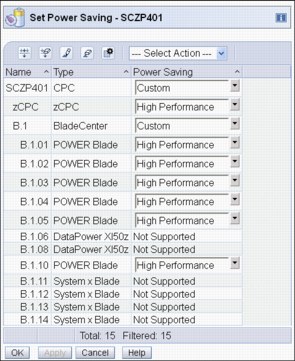
Figure 10-15 Set Power Saving window
For more information about Energy Management with Unified Resource Manager, see Building an Ensemble Using IBM zEnterprise Unified Resource Manager, SG24-7921.
10.5 zBX environmental requirements
The following sections address the environmental requirements for the zEnterprise BladeCenter Extension (zBX). For more information about the environmental requirements for the zBX, see zBX Installation Manual for Physical Planning 2458-003, GC27-2619.
|
zBX and z13: A new zBX Model 004 cannot be ordered from IBM. A zBX Model 004 is the result of an MES from a zBX Model 002 or from a zBX Model 003 only. After a zBX is upgraded to a Model 004, it becomes a stand-alone box that can be added to an existing ensemble as an ensemble member (or node).
|
10.5.1 zBX configurations
The zBX can have 1 - 4 racks. The racks are shipped separately, and are bolted together at installation time. Each rack can contain up to two BladeCenter chassis, and each chassis can contain up to 14 single-wide blades. The total number of blades determines the actual components that are required for each configuration. The number of blades determines the number of BladeCenters and racks, as shown in Table 10-7.
Table 10-7 zBX configurations
|
Number of blades
|
Number of BladeCenters
|
Number of racks
|
|
7
|
1
|
1
|
|
14
|
1
|
1
|
|
28
|
2
|
1
|
|
42
|
3
|
2
|
|
56
|
4
|
2
|
|
70
|
5
|
3
|
|
84
|
6
|
3
|
|
98
|
7
|
4
|
|
112
|
8
|
4
|
A zBX can be populated with up to 112 POWER7 blades. A maximum of 56 IBM BladeCenter HX5 blades can be installed in a zBX. For DataPower blades, the maximum number is 28 because they are double-wide.
|
Note: A zBX can have only the number of entitlements changed along with the upgrade miscellaneous equipment specification (MES). To increase the zBX Model 004 entitlement records, available slots in the BladeCenter systems are required. After the entitlements are added, new blades can be installed up to the entitlement record limits. The addition of new racks or BladeCenter systems is not available.
|
10.5.2 zBX power components
The zBX has its own power supplies and cords that are independent of the zEnterprise server power. Depending on the configuration of the zBX, up to 16 client-supplied power feeds might be required. A fully configured four-rack zBX has 16 Power Distribution Units (PDUs).
As mentioned, when upgrading an existing zBX Model 002 or zBX Model 003 to a zBX Model 004, the number of existing racks and blade centers is maintained.
The zBX operates with the following characteristics:
•50/60Hz AC power
•Voltage (240 V)
•Both single-phase and three-phase wiring
PDUs and power cords
The zBX has these available PDU options:
•FC 0520 - 7176 Model 3NU with attached power cord (US)
•FC 0521 - 7176 Model 2NX (WW)
The following power cord options are available for the zBX:
•FC 0531 - 4.3 meter, 60A/208V, US power cord, Single Phase.
•FC 0532 - 4.3 meter, 63A/230V, non-US power cord, Single Phase.
•FC 0533 - 4.3 meter, 32A/380V-415V, non-US power cord, Three Phase. 32A WYE 380 V provides a 220 V line to neutral, and 32A WYE 415 V provides a 240 V line to neutral. This setting ensures that the BladeCenter maximum of 240 V is not exceeded.
|
Note: If a zBX Model 002 or 003 with a single rack and a single BladeCenter installed is upgraded to a zBX Model 004, a pair of new PDUs along with the two power cord line drops are added to the existing Frame B to provide AC power for the two new 1U zBX SEs.
|
Power installation considerations
Each zBX BladeCenter operates from two fully redundant PDUs that are installed in the rack with the BladeCenter. These PDUs each have their own power cords, as shown in Table 10-8. This configuration allows the system to survive the loss of the client’s power to either power cord. If power is interrupted to one of the PDUs, the other PDU picks up the entire load and the BladeCenter continues to operate without interruption.
Table 10-8 Number of BladeCenter power cords
|
Number of BladeCenter systems
|
Number of power cords
|
|
1
|
2
|
|
2
|
4
|
|
3
|
6
|
|
4
|
8
|
|
5
|
10
|
|
6
|
12
|
|
7
|
14
|
|
8
|
16
|
A zBX can be populated by up to 112 Power 701 blades. A maximum of 56 IBM BladeCenter HX5 blades can be installed in a zBX. For DataPower blades, the maximum number is 28.
|
DataPower blades: The DataPower blade is a double-wide blade.
|
For maximum availability, attach the power cords on each side of the racks to different building power distribution units.
Actual power consumption is dependent on the zBX configuration in terms of the number of BladeCenter systems and blades that are installed. Input power in kVA is equal to the output power in kW. Heat output, expressed in kBTU per hour, is derived by multiplying the table entries by a factor of 3.4. For 3-phase installations, phase balancing is accomplished with the power cable connectors between the BladeCenter systems and the PDUs.
|
Note: When a zBX Model 002 or 003 is upgraded to a zBX Model 004 and blades are added to the existing blade centers, you must plan for the new power consumption that results from the new installed blade configuration. For more information about this task, see the zBX Model 004 Installation Manual and Physical Planning (IMPP), GC27-2630.
|
10.5.3 zBX cooling
The individual BladeCenter configuration is air-cooled with two hot-swap blower modules. The blower speeds vary depending on the ambient air temperature at the front of the BladeCenter unit and the temperature of internal BladeCenter components:
•If the ambient temperature is 25°C (77°F) or below, the BladeCenter unit blowers run at their minimum rotational speed. They increase their speed as required to control the internal BladeCenter temperature.
•If the ambient temperature is above 25°C (77°F), the blowers run faster, increasing their speed as required to control the internal BladeCenter unit temperature.
•If a blower fails, the remaining blower runs at full speed to cool the BladeCenter unit and blade servers.
Typical heat output
Table 10-9 shows the typical heat that is released by various zBX solution configurations.
Table 10-9 zBX power consumption and heat output
|
Number of blades
|
Max utility power (kW)
|
Heat output (kBTU/hour)
|
|
7
|
7.3
|
24.82
|
|
14
|
12.1
|
41.14
|
|
28
|
21.7
|
73.78
|
|
42
|
31.3
|
106.42
|
|
56
|
40.9
|
139.06
|
|
70
|
50.5
|
171.70
|
|
84
|
60.1
|
204.34
|
|
98
|
69.7
|
236.98
|
|
112
|
79.3
|
269.62
|
Optional Rear Door Heat eXchanger (FC 0540)
For data centers with limited cooling capacity, use the Rear Door Heat eXchanger (FC 0540), as shown in Figure 10-16 on page 408. It is a more cost-effective solution than adding another air conditioning unit.
|
Rear Door Heat eXchanger: The Rear Door Heat eXchanger is not a requirement for BladeCenter cooling. It is a solution for clients that cannot upgrade a data center’s air conditioning units because of space, budget, or other constraints.
|
The Rear Door Heat eXchanger has the following features:
•A water-cooled heat exchanger door is designed to dissipate heat that is generated from the back of the computer systems before it enters the room.
•An easy-to-mount rear door design attaches to client-supplied water, using industry standard fittings and couplings.
• Up to 50,000 BTUs (or approximately 15 kW) of heat can be removed from the air that is exiting the back of a zBX rack.
The IBM Rear Door Heat eXchanger details are shown in Figure 10-16.

Figure 10-16 Rear Door Heat eXchanger (left) and functional diagram
The IBM Rear Door Heat eXchanger also offers a convenient way to handle hazardous “hot spots”, which can help you lower the total energy cost of the data center.
10.5.4 zBX physical specifications
The zBX solution is delivered either with one rack (Rack B) or four racks (Racks B, C, D, and E). Table 10-10 shows the physical dimensions of the zBX minimum and maximum solutions.
Table 10-10 Dimensions of zBX racks
|
Racks with
covers
|
Width
mm (in.)
|
Depth
mm (in.)
|
Height
mm (in.)
|
|
B
|
648 (25.5)
|
1105 (43.5)
|
2020 (79.5)
|
|
B + C
|
1296 (51.0)
|
1105 (43.5)
|
2020 (79.5)
|
|
B + C + D
|
1994 (76.5)
|
1105 (43.5)
|
2020 (79.5)
|
|
B + C + D + E
|
2592 (102)
|
1105 (43.5)
|
2020 (79.5)
|
Top Exit Support feature (FC 0545)
This feature (Figure 10-17) allows you to route I/O and power cabling through the top of the zBX rack. The feature adds 177 mm (7 in.) to the height and 9.75 kg (21.5 lbs) to the weight of the zBX rack after it is installed. It can be ordered as an additional feature. You must have one feature per installed rack.
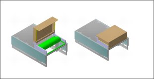
Figure 10-17 Top Exit Support feature for the zBX
zBX weight
Table 10-11 lists the maximum weights of fully populated zBX racks and BladeCenter systems.
Table 10-11 Weights of zBX racks
|
Rack description
|
Weight kgs (lbs)
|
|
B with 28 blades
|
740 (1630)
|
|
B + C full
|
1234 (2720)
|
|
B + C + D full
|
1728 (3810)
|
|
B + C + D + E full
|
2222 (4900)
|
|
Remember: A fully configured Rack B is heavier than a fully configured Rack C, D, or E because Rack B has the Top of Rack (ToR) switches, SEs, and consoles installed.
|
For more information about the physical requirements for zBX, see zBX Model 004 Installation Manual for Physical Planning, GC27-2630.
..................Content has been hidden....................
You can't read the all page of ebook, please click here login for view all page.