


Central processor complex system design
This chapter explains how the IBM z13 processor unit is designed. This information can be used to understand the functions that make the z13 a system that accommodates a broad mix of workloads for large enterprises.
This chapter includes the following sections:
3.1 Overview
The z13 symmetric multiprocessor (SMP) system is the next step in an evolutionary trajectory that began with the introduction of the IBM System/360 in1964. Over time, the design was adapted to the changing requirements that were dictated by the shift toward new types of applications that clients depend on.
The IBM z13 offers high levels of reliability, availability, serviceability, resilience, and security. It fits into the IBM strategy in which mainframes play a central role in creating an infrastructure for cloud, analytics, and mobile, underpinned by security. The z13 is designed so that everything around it, such as operating systems, middleware, storage, security, and network technologies that support open standards, help you achieve your business goals.
The modular CPC drawer design aims to reduce, or in some cases even eliminate, planned and unplanned outages. The design does so by offering concurrent repair, replace, and upgrade functions for processors, memory, and I/O. For more information about the z13 reliability, availability, and serviceability (RAS) features, see Chapter 9, “Reliability, availability, and serviceability” on page 353.
The z13 has ultra-high frequency, large high-speed buffers (caches) and memory, superscalar processor design, out-of-order core execution, simultaneous multithreading (SMT), single-instruction multiple-data (SIMD), and flexible configuration options. It is the next implementation of z Systems to address the ever-changing IT environment.
3.2 Design highlights
The physical packaging of the z13 is different from zEnterprise zEC12 (zEC12) systems. Its modular CPC drawer and single chip module (SCM) design address the augmenting costs that are related to building systems with ever-increasing capacities. The modular CPC drawer design is flexible and expandable, offering unprecedented capacity to meet consolidation needs, and might contain even larger capacities in the future.
z13 continues the line of mainframe processors that are compatible with an earlier version. It introduces more complex instructions that are run by millicode, and more complex instructions that are broken down into multiple operations. It uses 24-bit, 31-bit, and 64-bit addressing modes, multiple arithmetic formats, and multiple address spaces for robust interprocess security.
The z13 system design has the following main objectives:
•Offer a flexible infrastructure to concurrently accommodate a wide range of operating systems and applications, which range from the traditional systems (for example, z/OS and z/VM) to the world of Linux, cloud, analytics, and mobile computing.
•Offer state-of-the-art integration capability for server consolidation by using virtualization capabilities in a highly secure environment:
– Logical partitioning, which allows 85 independent logical servers.
– z/VM, which can virtualize hundreds to thousands of servers as independently running virtual machines (guests).
– HiperSockets, which implement virtual LANs between logical partitions (LPARs) within the system.
– The z Systems PR/SM is designed for Common Criteria Evaluation Assurance Level 5+ (EAL 5+) certification for security, so an application running on one partition (LPAR) cannot access another application on a different partition, providing essentially the same security as an air-gapped system.
This configuration allows for a logical and virtual server coexistence and maximizes system utilization and efficiency by sharing hardware resources.
•Offer high performance computing to achieve the outstanding response times that are required by new workload-type applications. This performance is achieved by high frequency, enhanced superscalar processor technology, out-of-order core execution, large high-speed buffers (cache) and memory, an architecture with multiple complex instructions, and high-bandwidth channels.
•Offer the high capacity and scalability that are required by the most demanding applications, both from the single-system and clustered-systems points of view.
•Offer the capability of concurrent upgrades for processors, memory, and I/O connectivity, which prevents system outages in planned situations.
•Implement a system with high availability and reliability. These goals are achieved with the redundancy of critical elements and sparing components of a single system, and the clustering technology of the Parallel Sysplex environment.
•Have internal and external connectivity offerings, supporting open standards, such as Gigabit Ethernet (GbE) and Fibre Channel Protocol (FCP).
•Provide leading cryptographic performance. Every processor unit (PU) has a dedicated and optimized CP Assist for Cryptographic Function (CPACF). Optional Crypto Express features with cryptographic coprocessors provide the highest standardized security certification.1 These optional features can also be configured as Cryptographic Accelerators to enhance the performance of Secure Sockets Layer/Transport Layer Security (SSL/TLS) transactions.
•Be self-managing and self-optimizing, adjusting itself when the workload changes to achieve the best system throughput. This process can be done through the Intelligent Resource Director or the Workload Manager functions, which are assisted by HiperDispatch.
•Have a balanced system design, providing large data rate bandwidths for high performance connectivity along with processor and system capacity.
The remaining sections describe the z13 system structure, showing a logical representation of the data flow from PUs, caches, memory cards, and various interconnect capabilities.
3.3 CPC drawer design
A z13 system can have up to four CPC drawers in a full configuration, up to 141 PUs that can be characterized, and up to 10 TB of customer usable memory capacity. Each CPC drawer is physically divided in two nodes to improve the processor and memory affinity and availability. The topology is shown in Figure 3-5 on page 88.
The memory has up to 24 memory controllers, but only 20 populated memory controller units (MCUs) (five MCUs per CPC drawer), using 5-channel redundant array of independent memory (RAIM) protection, with dual inline memory modules (DIMM) bus cyclic redundancy check (CRC) error retry. The 4-level cache hierarchy is implemented with eDRAM (embedded) caches. Until recently, eDRAM was considered to be too slow for this use. However, a breakthrough in technology made by IBM has erased that limitation. In addition, eDRAM offers higher density, less power utilization, fewer soft errors, and better performance. Concurrent maintenance allows dynamic CPC drawer add and repair.2
The z13 uses CMOS 14S0 SOI3 22 nm chip technology, with advanced low latency pipeline design, creating high-speed yet power-efficient circuit designs. The PU SCM has a dense packaging, allowing closed water loop cooling. The heat exchange from the closed loop is either air-cooled by a radiator unit (RU) or, optionally, water-cooled by a water-cooling unit (WCU). The water-cooling option can lower the total power consumption of the system. This benefit is significant for larger configurations. For more information, see 2.8.6, “Cooling” on page 73.
3.3.1 Cache levels and memory structure
The z13 memory subsystem focuses on keeping data “closer” to the PU core. With the current processor configuration, all cache levels have increased, and the second-level private cache (L2) and the total node-level shared cache (L4) in a CPC drawer have doubled in size.
Figure 3-1 shows the z13 cache levels and memory hierarchy.

Figure 3-1 z13 cache levels and memory hierarchy
The 4-level cache structure is implemented within the storage control (SC) SCMs. There is one L4 cache in each node of the CPC drawer. The first three levels (L1, L2, and L3) are on each PU chip (PU SCM), and L4 is on the SC chips (SC SCMs):
•L1 and L2 caches use static random-access memory (SRAM), and are private for each core.
•L3 cache uses embedded dynamic static random access memory (eDRAM) and is shared by all eight cores within the PU chip. Each CPC drawer has six L3 caches. A four-CPC drawer system therefore has 24 of them, resulting in 1536 MB (24 x 64 MB) of this shared PU chip-level cache.
•L4 cache also uses eDRAM, and is shared by all PU chips on the node of a CPC drawer. Each L4 cache has 480 MB for previously owned and some L3-owned lines (LRU) and 224 MB for a non-data inclusive coherent (NIC) directory that points to L3 owned lines that have not been included in L4 cache. A four-CPC drawer system has 3840 MB (4 x 2 x 384 MB) of shared L4 cache and 1792 MB (4 x 2 x 224 MB) of NIC directory.
•Main storage has up to 2.5 TB addressable memory per CPC drawer, using 20 or 25 DIMMs. A four-CPC drawer system can have up to 10 TB of main storage.
Considerations
Cache sizes are being limited by ever-diminishing cycle times because they must respond quickly without creating bottlenecks. Access to large caches costs more cycles. Instruction and data cache (L1) sizes must be limited because larger distances must be traveled to reach long cache lines. This L1 access time generally occurs in one cycle, which prevents increased latency.
Also, the distance to remote caches as seen from the microprocessor becomes a significant factor. An example is an L4 cache that is not on the microprocessor (and might not even be in the same CPC drawer). Although the L4 cache is rather large, several cycles are needed to travel the distance to the cache. Figure 3-2 shows the node-cache topology of z13.

Figure 3-2 z13 caches topology
Although large caches mean increased access latency, the new technology of CMOS 14S0 (22 nm chip lithography) and the lower cycle time allows z13 to increase the size of cache levels (L1, L2, and L3) within the PU chip by using denser packaging. This design reduces traffic to and from the shared L4 cache, which is on another chip (SC chip). Only when there is a cache miss in L1, L2, or L3 is a request sent to L4. L4 is the coherence manager, which means that all memory fetches must be in the L4 cache before that data can be used by the processor. However, in the z13 cache design, some lines of the L3 cache are not included in the L4 cache. The L4 cache has an NIC directory that has entries that point to the non-inclusive lines of L3 cache. This design ensures that L3 locally owned lines (same node) can be accessed over the X-bus by using the intra-node snoop interface without being included in L4. Inter-node snoop traffic to L4 can still be handled effectively.
Another approach is available for avoiding L4 cache access delays (latency). The L4 cache straddles up to four CPC drawers and up to eight nodes. This configuration means that relatively long distances exist between the higher-level caches in the processors and the L4 cache content. To overcome the delays that are inherent in the SMP CPC drawer design and save cycles to access the remote L4 content, keep instructions and data as close to the processors as possible. You can do so by directing as much work of a particular LPAR workload to the processors in the same CPC drawer as the L4 cache. This configuration is achieved by having the IBM Processor Resource/Systems Manager (PR/SM) scheduler and the z/OS WLM and dispatcher work together. Have them keep as much work as possible within the boundaries of as few processors and L4 cache space (which is best within a node of a CPC drawer boundary) without affecting throughput and response times.
Figure 3-3 compares the cache structures of the z13 with the previous generation of z Systems, the zEC12.

Figure 3-3 z13 and zEC12 cache level comparison
Compared to zEC12, the z13 cache design has much larger cache level sizes. In z13, there is more affinity between the memory of a partition, the L4 cache in the SC SCM, and the cores in the PU SCMs of a node of a CPC drawer. The access time of the private cache usually occurs in one cycle. The z13 cache level structure is focused on keeping more data closer to the PU. This design can improve system performance on many production workloads.
HiperDispatch
To help avoid latency in a high-frequency processor design, such as the z13, prevent PR/SM and the dispatcher from scheduling and dispatching a workload on any processor available, and keep the workload in as small a portion of the system as possible. The cooperation between z/OS and PR/SM is bundled in a function called HiperDispatch. HiperDispatch uses the z13 cache topology, which has reduced cross-node “help” and better locality for multi-task address spaces.
PR/SM can use dynamic PU reassignment to move processors (CPs, ZIIPs, IFLs, ICFs, SAPs, and spares) to a different chip, node, and drawer to improve the reuse of shared caches by processors of the same partition. It can use dynamic memory relocation (DMR) to move a running partition’s memory to different physical memory to improve the affinity and reduce the distance between the memory of a partition and the processors of the partition. For more information about HiperDispatch, see 3.7, “Logical partitioning” on page 116.
3.3.2 CPC drawer interconnect topology
CPC drawers are interconnected in a point-to-point topology, allowing a node in a CPC drawer to communicate with every other node (eight nodes in four CPC drawers). Data transfer does not always have to go through another node or processor drawer (cache) to address the requested data or control information.
Figure 3-4 shows the z13 inter-CPC drawer communication structure.

Figure 3-4 z13 CPC drawer communication topology
Figure 3-5 shows a simplified topology of a four-CPC drawer system.

Figure 3-5 Point-to-point topology four CPC drawers communication
Inter-CPC drawer communication takes place at the L4 cache level, which is implemented on SC cache chips in each node. The SC function regulates coherent node-to-node traffic.
3.4 Processor unit design
Processor cycle time is especially important for processor-intensive applications. Current systems design is driven by processor cycle time, although improved cycle time does not automatically mean that the performance characteristics of the system improve. The System z10 EC introduced a dramatic PU cycle time improvement. Its succeeding generations, the z196 and the zEC12, reduced the cycle time even further, reaching 0.192 ns (5.2 GHz) and 0.178 ns (5.5 GHz).
The z13 has a cycle time of 0.2 ns (5.0 GHz), which allows the increased number of processors that share larger caches to have quick access times and improved capacity and performance. Although the cycle time of the z13 processor was slightly increased compared to z196 and zEC12 (4% and 10%), the processor performance was increased through improved processor design, such as pipeline, out-of-order execution design, branch prediction, time of access to high-speed buffers (caches redesign), and the relative nest intensity (RNI). For more information about RNI, see 12.3, “Relative nest intensity” on page 459.
The z13 processor unit core is a superscalar, out-of-order (OOO), simultaneous multithreading (SMT) processor with 10 execution units. For instructions that are not directly run by the hardware, some are run by millicode, and others are split into multiple operations.
z13 introduces architectural extensions with instructions that are designed to allow reduced processor quiesce effects, reduced cache misses, reduced pipeline disruption, and increased parallelism with instructions that process several operands in a single instruction (SIMD). The z13 new architecture includes the following features:
•Simultaneous multithreading (SMT)
•SIMD instructions set
•Out-of-order core execution
•Improvements in branch prediction and handling
•Performance per watt improvements when compared to the zEC12 system
•Enhanced instruction dispatch and grouping efficiency
•Enhanced branch prediction structure and sequential instruction fetching
•Millicode improvements
•Decimal floating-point (DFP) improvements
The z13 enhanced Instruction Set Architecture (ISA) includes a set of instructions that are added to improve compiled code efficiency. These instructions optimize PUs to meet the demands of a wide variety of business and analytics workload types without compromising the performance characteristics of traditional workloads.
3.4.1 Simultaneous multithreading (SMT)
The z13, aligned with industry directions, can process up to two simultaneous threads in a single core while sharing certain resources of the processor, such as execution units, translation lookaside buffers (TLBs), and caches. When one thread in the core is waiting for other hardware resources, the second thread in the core can use the shared resources rather than remaining idle. This capability is known as SMT.
SMT is supported only by Integrated Facility for Linux (IFL) and IBM z Systems Integrated Information Processor (zIIP) speciality engines on z13, and it requires operating system support. An operating system with SMT support can be configured to dispatch work to a thread on a zIIP (for eligible workloads in z/OS) or an IFL (for z/VM) core in single thread or SMT mode so that HiperDispacth cache optimization can be considered. For more information about operating system support, see Chapter 7, “Software support” on page 227.
To support SMT, the z13 has a double symmetric instruction pipeline width and full architectural state per thread. Beyond this, the CPU address changes and the 16-bit CPU ID consist of 15-bit core ID and a 1-bit thread ID. For example, the CPU ID 6 (b‘0000000000000110‘) means core 3 thread 0 and the CPU ID 7(b‘0000000000000111‘) means core 3 thread 1. For CPs, only thread 0 is used in each core.
SMT technology allows instructions from more than one thread to run in any pipeline stage at a time. Each thread has its own unique state information, such as PSW and registers. The simultaneous threads cannot necessarily run instructions instantly and must at times compete to use certain core resources that are shared between the threads. In some cases, threads can use shared resources that are not experiencing competition.
Figure 3-6 show two threads (A and B) running on the same processor core on different pipeline stages, sharing the core resources.

Figure 3-6 Two threads running simultaneously on the same processor core
The use of SMT provides more efficient use of the processors’ resources and helps address memory latency, resulting in overall throughput gains. The active thread shares core resources in space, such as data and instruction caches, TLBs, branch history tables, and, in time, pipeline slots, execution units, and address translators.
Although SMT increases the processing capacity, the performance in some cases might be superior if you use a single thread. Enhanced hardware monitoring supports measurement through CPUMF for thread usage and capacity.
For workloads that need maximum thread speed, the partition’s SMT mode can be turned off. For workloads that need more throughput to decrease the dispatch queue size, the partition’s SMT mode can be turned on.
The SMT exploitation is functionally transparent to middleware and applications, and no changes are required to run them in an SMT-enabled partition.
3.4.2 Single-instruction multiple-data (SIMD)
The z13 superscalar processor has 32 vector registers and an instruction set architecture that includes a subset of 139 new instructions, known as SIMD, added to improve the efficiency of complex mathematical models and vector processing. These new instructions allow a larger number of operands to be processed with a single instruction. The SIMD instructions use the superscalar core to process operands in parallel.
SIMD provides the next phase of enhancements of z Systems analytics capability. The set of SIMD instructions are a type of data parallel computing and vector processing that can decrease the amount of code and accelerate code that handles integer, string, character, and floating point data types. The SIMD instructions improve performance of complex mathematical models and allow integration of business transactions and analytic workloads on z Systems.
The 32 new vector registers have 128 bits. The 139 new instructions include string operations, vector integer, and vector floating point operations. Each register contains multiple data elements of a fixed size. The instructions code specifies which data format to use and whether the size of the elements is byte (sixteen 8-bit operands), halfword (eight 16-bit operands), word (four 32-bit operands), doubleword (two 64- bit operands), or quadword (one 128-bit operand). The collection of elements in a register is called a vector. A single instruction operates on all of the elements in the register. Instructions have a non-destructive operand encoding that allows the addition of the register vector A and register vector B and stores the result in the register vector A (A = A + B).
Figure 3-7 shows a schematic representation of a SIMD instruction with 16-byte size elements in each vector operand.

Figure 3-7 Schematic representation of add SIMD instruction with 16 elements in each vector
The vector register file overlays the floating-point registers (FPRs), as shown in Figure 3-8. The FPRs use the first 64 bits of the first 16 vector registers, which saves hardware area and power, and makes it easier to mix scalar and SIMD codes. Effectively, the core gets 64 FPRs, which can further improve FP code efficiency.

Figure 3-8 Floating point registers overlaid by vector registers
Here are some examples of SIMD instructions:
•Integer byte to quadword add, sub, and compare
•Integer byte to doubleword min, max, and average
•Integer byte to word multiply
•String find 8-bits, 16-bits, and 32-bits
•String range compare
•String find any equal
•String load to block boundaries and load/store with length
For most operations, the condition code (CC) is not set. A summary CC is used only for a few instructions.
3.4.3 Out-of-order (OOO) execution
The z13 has an OOO core, much like the previous systems z196 and zEC12. OOO yields significant performance benefits for compute-intensive applications. It does so by reordering instruction execution, allowing later (younger) instructions to be run ahead of a stalled instruction, and reordering storage accesses and parallel storage accesses. OOO maintains good performance growth for traditional applications. Out-of-order execution can improve performance in the following ways:
•Reordering instruction execution: Instructions stall in a pipeline because they are waiting for results from a previous instruction or the execution resource that they require is busy. In an in-order core, this stalled instruction stalls all later instructions in the code stream. In an out-of-order core, later instructions are allowed to run ahead of the stalled instruction.
•Reordering storage accesses: Instructions that access storage can stall because they are waiting on results that are needed to compute the storage address. In an in-order core, later instructions are stalled. In an out-of-order core, later storage-accessing instructions that can compute their storage address are allowed to run.
•Hiding storage access latency: Many instructions access data from storage. Storage accesses can miss the L1 and require 7 - 50 more clock cycles to retrieve the storage data. In an in-order core, later instructions in the code stream are stalled. In an out-of-order core, later instructions that are not dependent on this storage data are allowed to run.
The z13 processor has pipeline enhancements that benefit OOO execution. The z Systems processor design has advanced micro-architectural innovations that provide these benefits:
•Maximized instruction-level parallelism (ILP) for a better cycles per instruction (CPI) design by reviewing every part of the z196 design.
•Maximized performance per watt. Two cores are added, as compared to the z196 chip, at slightly higher chip power (~300 watts).
•Enhanced instruction dispatch and grouping efficiency.
•Increased OOO resources (Global Completion Table entries, physical GPR entries, and physical FPR entries).
•Improved completion rate.
•Reduced cache/TLB miss penalty.
•Improved execution of D-Cache store and reload and new Fixed-point divide.
•New OSC (load-hit-store conflict) avoidance scheme.
•Enhanced branch prediction structure and sequential instruction fetching.
Program results
The OOO execution does not change any program results. Execution can occur out of (program) order, but all program dependencies are honored, ending up with the same results of the in-order (program) execution.
This implementation requires special circuitry to make execution and memory accesses display in order to the software. The logical diagram of a z13 core is shown in Figure 3-9.

Figure 3-9 z13 PU core logical diagram
Memory address generation and memory accesses can occur out of (program) order. This capability can provide a greater use of the z13 superscalar core, and can improve system performance. Figure 3-10 shows how OOO core execution can reduce the run time of a program.

Figure 3-10 In-order and z13 out-of-order core execution improvements
The left side of Figure 3-10 on page 93 shows an in-order core execution. Instruction 2 has a large delay because of an L1 cache miss, and the next instructions wait until instruction 2 finishes. In the usual in-order execution, the next instruction waits until the previous instruction finishes. Using OOO core execution, which is shown on the right side of Figure 3-10 on page 93, instruction 4 can start its storage access and run while instruction 2 is waiting for data. This situation occurs only if no dependencies exist between the two instructions. When the L1 cache miss is solved, instruction 2 can also start its run while instruction 4 is running. Instruction 5 might need the same storage data that is required by instruction 4. As soon as this data is on L1 cache, instruction 5 starts running at the same time. The z13 superscalar PU core can have up to 10 instructions/operations running per cycle. This technology results in a shorter run time.
Branch prediction
If the branch prediction logic of the microprocessor makes the wrong prediction, removing all instructions in the parallel pipelines might be necessary. The wrong branch prediction is expensive in a high-frequency processor design. Therefore, the branch prediction techniques that are used are important to prevent as many wrong branches as possible.
For this reason, various history-based branch prediction mechanisms are used, as shown on the in-order part of the z13 PU core logical diagram in Figure 3-9 on page 93. The branch target buffer (BTB) runs ahead of instruction cache pre-fetches to prevent branch misses in an early stage. Furthermore, a branch history table (BHT) in combination with a pattern history table (PHT) and the use of tagged multi-target prediction technology branch prediction offer a high branch prediction success rate.
The z13 microprocessor improves the branch prediction throughput by using the new branch prediction and instruction fetch front end.
3.4.4 Superscalar processor
A scalar processor is a processor that is based on a single-issue architecture, which means that only a single instruction is run at a time. A superscalar processor allows concurrent (parallel) execution of instructions by adding more resources to the microprocessor in multiple pipelines, each working on its own set of instructions to create parallelism.
A superscalar processor is based on a multi-issue architecture. However, when multiple instructions can be run during each cycle, the level of complexity is increased because an operation in one pipeline stage might depend on data in another pipeline stage. Therefore, a superscalar design demands careful consideration of which instruction sequences can successfully operate in a long pipeline environment.
On the z13, up to six instructions can be decoded per cycle and up to 10 instructions or operations can be in execution per cycle. Execution can occur out of (program) order. These improvements also make possible the simultaneous execution of two threads in the same processor.
Many challenges exist in creating an efficient superscalar processor. The superscalar design of the PU has made significant strides in avoiding address generation interlock (AGI) situations. Instructions that require information from memory locations can suffer multi-cycle delays to get the needed memory content. Because high-frequency processors wait “faster” (spend processor cycles more quickly while idle), the cost of getting the information might become prohibitive.
3.4.5 Compression and cryptography accelerators on a chip
This section describes the compression and cryptography features.
Coprocessor units
There is one coprocessor (CoP) unit for compression and cryptography on each core in the chip. The compression engine uses static dictionary compression and expansion. The dictionary size is up to 64 KB, with 8 K entries, and has a local 16 KB cache for dictionary data.
The cryptography engine is used for the CP Assist for Cryptographic Function (CPACF), which offers a set of symmetric cryptographic functions for encrypting and decrypting of clear key operations.
Here are some of the characteristics of the z13 coprocessors:
•Each core has an independent compression and cryptographic engine.
•COP has been redesigned from scratch to support SMT operation.
•It is available to any processor type.
•The owning processor is busy when its coprocessor is busy.
Figure 3-11 shows the location of the coprocessor on the chip.

Figure 3-11 Compression and cryptography accelerators on a core in the chip
CP assist for cryptographic function
CPACF accelerates the encrypting and decrypting of SSL/TLS transactions, virtual private network (VPN)-encrypted data transfers, and data-storing applications that do not require FIPS4 140-2 level 4 security. The assist function uses a special instruction set for symmetrical clear key cryptographic encryption and decryption, and for hash operations. This group of instructions is known as the Message-Security Assist (MSA). For more information about these instructions, see z/Architecture Principles of Operation, SA22-7832.
For more information about cryptographic functions on z13, see Chapter 6, “Cryptography” on page 197.
3.4.6 Decimal floating point (DFP) accelerator
The DFP accelerator function is present on each of the microprocessors (cores) on the 8-core chip. Its implementation meets business application requirements for better performance, precision, and function.
Base 10 arithmetic is used for most business and financial computation. Floating point computation that is used for work that is typically done in decimal arithmetic involves frequent data conversions and approximation to represent decimal numbers. This has made floating point arithmetic complex and error-prone for programmers who use it for applications in which the data is typically decimal.
Hardware decimal floating point computational instructions provide the following features:
•Data formats of 4 bytes, 8 bytes, and 16 bytes
•An encoded decimal (base 10) representation for data
•Instructions for running decimal floating point computations
•An instruction that runs data conversions to and from the decimal floating point representation
Benefits of the DFP accelerator
The DFP accelerator offers the following benefits:
•Avoids rounding issues, such as those that happen with binary-to-decimal conversions.
•Controls existing binary-coded decimal (BCD) operations better.
•Follows the standardization of the dominant decimal data and decimal operations in commercial computing supporting industry standardization (IEEE 745R) of decimal floating point operations. Instructions are added in support of the Draft Standard for Floating-Point Arithmetic - IEEE 754-2008, which is intended to supersede the ANSI/IEEE Standard 754-1985.
•Allows COBOL programs that use zoned-decimal operations to take advantage of the z/Architecture DFP instructions.
The z13 has two DFP accelerator units per core, which improve the decimal floating point execution bandwidth. The floating point instructions operate on newly designed vector registers (32 new 128-bit registers).
The z13 has new decimal floating point packed conversion facility support with the following benefits:
•Reduces code path length because extra instructions to format conversion are not needed anymore.
•Packed data is operated in memory by all decimal instructions without general-purpose registers, which were required only to prepare for decimal floating point packed conversion instruction.
•Converting from packed can now force the input packed value to positive instead of requiring a separate OI, OILL, or load positive instruction.
•Converting to packed can now force a positive zero result instead of requiring ZAP instruction.
Software support
Decimal floating point is supported in the following programming languages and products:
•Release 4 and later of the High Level Assembler
•C/C++ (requires z/OS 1.10 with program temporary fixes (PTFs) for full support or later)
•Enterprise PL/I Release 3.7 and Debug Tool Release 8.1 or later
•Java Applications using the BigDecimal Class Library
•SQL support as of DB2 Version 9 or later
3.4.7 IEEE floating point
Binary and hexadecimal floating-point instructions are implemented in z13. They incorporate IEEE standards into the system.
The key point is that Java and C/C++ applications tend to use IEEE BFP operations more frequently than earlier applications. Therefore, the better the hardware implementation of this set of instructions, the better the performance of applications.
3.4.8 Processor error detection and recovery
The PU uses a process called transient recovery as an error recovery mechanism. When an error is detected, the instruction unit tries the instruction again and attempts to recover the error. If the second attempt is unsuccessful (that is, a permanent fault exists), a relocation process is started that restores the full capacity by moving work to another PU. Relocation under hardware control is possible because the R-unit has the full designed state in its buffer. The principle is shown in Figure 3-12.

Figure 3-12 PU error detection and recovery
3.4.9 Branch prediction
Because of the ultra-high frequency of the PUs, the penalty for a wrongly predicted branch is high. Therefore, a multi-pronged strategy for branch prediction, based on gathered branch history that is combined with other prediction mechanisms, is implemented on each microprocessor.
The BHT implementation on processors provides a large performance improvement. Originally introduced on the IBM ES/9000 9021 in 1990, the BHT is continuously improved.
The BHT offers significant branch performance benefits. The BHT allows each PU to take instruction branches based on a stored BHT, which improves processing times for calculation routines. In addition to the BHT, the z13 uses various techniques to improve the prediction of the correct branch to be run. The following techniques are used:
•Branch history table (BHT)
•Branch target buffer (BTB)
•Pattern history table (PHT)
•BTB data compression
The success rate of branch prediction contributes significantly to the superscalar aspects of the z13. This is because the architecture rules prescribe that, for successful parallel execution of an instruction stream, the correctly predicted result of the branch is essential.
3.4.10 Wild branch
When a bad pointer is used or when code overlays a data area that contains a pointer to code, a random branch is the result. This process causes a 0C1 or 0C4 abend. Random branches are hard to diagnose because clues about how the system got there are not evident.
With the wild branch hardware facility, the last address from which a successful branch instruction was run is kept. z/OS uses this information with debugging aids, such as the SLIP command, to determine where a wild branch came from. It might also collect data from that storage location. This approach decreases the number of debugging steps that are necessary when you want to know from where the branch came from.
3.4.11 Translation lookaside buffer (TLB)
The TLB in the instruction and data L1 caches use a secondary TLB to enhance performance. In addition, a translator unit is added to translate misses in the secondary TLB.
The size of the TLB is kept as small as possible because of its short access time requirements and hardware space limitations. Because memory sizes have recently increased significantly as a result of the introduction of 64-bit addressing, a smaller working set is represented by the TLB. To increase the working set representation in the TLB without enlarging the TLB, large (1 MB) page and giant page (2 GB) support is available and can be used when appropriate. For more information, see “Large page support” on page 113.
With the enhanced DAT-2 (EDAT-2) improvements, the z Systems introduce architecture enhancements to allow support for 2 GB page frames.
3.4.12 Instruction fetching, decoding, and grouping
The superscalar design of the microprocessor allows for the decoding of up to six instructions per cycle and the execution of up to 10 instructions per cycle. Both execution and storage accesses for instruction and operand fetching can occur out of sequence.
Instruction fetching
Instruction fetching normally tries to get as far ahead of instruction decoding and execution as possible because of the relatively large instruction buffers available. In the microprocessor, smaller instruction buffers are used. The operation code is fetched from the I-cache and put in instruction buffers that hold prefetched data that are awaiting decoding.
Instruction decoding
The processor can decode up to six instructions per cycle. The result of the decoding process is queued and later used to form a group.
Instruction grouping
From the instruction queue, up to 10 instructions can be completed on every cycle. A complete description of the rules is beyond the scope of this book.
The compilers and JVMs are responsible for selecting instructions that best fit with the superscalar microprocessor. They abide by the rules to create code that best uses the superscalar implementation. All the z Systems compilers and the JVMs are constantly updated to benefit from new instructions and advances in microprocessor designs.
3.4.13 Extended Translation Facility
Instructions have been added to the z/Architecture instruction set in support of the Extended Translation Facility. They are used in data conversion operations for Unicode data, causing applications that are enabled for Unicode or globalization to be more efficient. These data-encoding formats are used in web services, grid, and on-demand environments where XML and SOAP technologies are used. The High Level Assembler supports the Extended Translation Facility instructions.
3.4.14 Instruction set extensions
The processor supports many instructions to support functions:
•Hexadecimal floating point instructions for various unnormalized multiply and multiply-add instructions.
•Immediate instructions, including various add, compare, OR, exclusive-OR, subtract, load, and insert formats. Use of these instructions improves performance.
•Load instructions for handling unsigned halfwords, such as those used for Unicode.
•Cryptographic instructions, which are known as the MSA, offer the full complement of the AES, SHA-1, SHA-2, and DES algorithms. They also include functions for random number generation.
•Extended Translate Facility-3 instructions, enhanced to conform with the current Unicode 4.0 standard.
•Assist instructions that help eliminate hypervisor processor usage.
•Single-instruction multiple-data (SIMD) instructions, which allow the parallel processing of multiple elements in a single instruction.
3.4.15 Transactional Execution
The Transactional Execution (TX) capability, which is known in the industry as hardware transactional memory, runs a group of instructions atomically, that is, either all their results are committed or no result is committed. The execution is optimistic. The instructions are run, but previous state values are saved in a “transactional memory”. If the transaction succeeds, the saved values are discarded. Otherwise, they are used to restore the original values.
The Transaction Execution Facility provides instructions, including declaring the beginning and end of a transaction, and canceling the transaction. TX is expected to provide significant performance benefits and scalability by avoiding most locks. This benefit is especially important for heavily threaded applications, such as Java.
3.4.16 Runtime Instrumentation
Runtime Instrumentation (RI) is a hardware facility for managed run times, such as the Java Runtime Environment (JRE). RI allows dynamic optimization of code generation as it is being run. It requires fewer system resources than the current software-only profiling, and provides information about hardware and program characteristics. It enhances JRE in making the correct decision by providing real-time feedback.
3.5 Processor unit (PU) functions
This section describes the PU functions.
3.5.1 Overview
All PUs on a z13 are physically identical. When the system is initialized, one integrated firmware processor (IFP) is allocated from the pool of PUs that is available for the whole system. The other PUs can be characterized to specific functions (CP, IFL, ICF, zIIP, or SAP).
The function that is assigned to a PU is set by the Licensed Internal Code (LIC). The LIC is loaded when the system is initialized (at power-on reset (POR)) and the PUs are characterized.
Only characterized PUs have a designated function. Non-characterized PUs are considered spares. Order at least one CP, IFL, or ICF on a z13.
This design brings outstanding flexibility to the z13 because any PU can assume any available characterization. The design also plays an essential role in system availability because PU characterization can be done dynamically, with no system outage.
For more information about software level support of functions and features, see Chapter 7, “Software support” on page 227.
Concurrent upgrades
Except on a fully configured model, concurrent upgrades can be done by the LIC, which assigns a PU function to a previously non-characterized PU. Within the CPC drawer boundary or boundary of multiple CPC drawer, no hardware changes are required. The upgrade can be done concurrently through the following facilities:
•Customer Initiated Upgrade (CIU) for permanent upgrades
•On/Off Capacity on Demand (On/Off CoD) for temporary upgrades
•Capacity BackUp (CBU) for temporary upgrades
•Capacity for Planned Event (CPE) for temporary upgrades
If the PU chips in the installed CPC drawers have no available remaining PUs, an upgrade results in a model upgrade and the installation of an extra CPC drawer. However, there is a limit of four CPC drawers. CPC drawer installation is nondisruptive, but takes more time than a simple LIC upgrade.
For more information about Capacity on Demand, see Chapter 8, “System upgrades” on page 307.
PU sparing
In the rare event of a PU failure, the failed PU’s characterization is dynamically and transparently reassigned to a spare PU. The z13 has two spare PUs. PUs that are not characterized on a CPC configuration can also be used as additional spare PUs. For more information about PU sparing, see 3.5.10, “Sparing rules” on page 111.
PU pools
PUs that are defined as CPs, IFLs, ICFs, and zIIPs are grouped in their own pools, from where they can be managed separately. This configuration significantly simplifies capacity planning and management for LPARs. The separation also affects weight management because CP and zIIP weights can be managed separately. For more information, see “PU weighting” on page 101.
All assigned PUs are grouped in the PU pool. These PUs are dispatched to online logical PUs.
As an example, consider a z13 with 10 CPs, two IFLs, five zIIPs, and one ICF. This system has a PU pool of 18 PUs, called the pool width. Subdivision defines these pools:
•A CP pool of 10 CPs
•An ICF pool of one ICF
•An IFL pool of two IFLs
•A zIIP pool of five zIIPs
PUs are placed in the pools in the following circumstances:
•When the system is PORed
•At the time of a concurrent upgrade
•As a result of the addition of PUs during a CBU
•Following a capacity on-demand upgrade through On/Off CoD or CIU
PUs are removed from their pools when a concurrent downgrade takes place as the result of the removal of a CBU. They are also removed through On/Off CoD process and the conversion of a PU. When a dedicated LPAR is activated, its PUs are taken from the correct pools. This is also the case when an LPAR logically configures a PU on, if the width of the pool allows for it.
For an LPAR, logical PUs are dispatched from the supporting pool only. The logical CPs are dispatched from the CP pool, logical zIIPs from the zIIP pool, logical IFLs from the IFL pool, and the logical ICFs from the ICF pool.
PU weighting
Because CPs, zIIPs, IFLs, and ICFs have their own pools from where they are dispatched, they can be given their own weights. For more information about PU pools and processing weights, see the z Systems Processor Resource/Systems Manager Planning Guide, SB10-7162.
3.5.2 Central processors (CPs)
A CP is a PU that uses the full z/Architecture instruction set. It can run z/Architecture-based operating systems (z/OS, z/VM, TPF, z/TPF, z/VSE, and Linux), the Coupling Facility Control Code (CFCC), and IBM zAware. Up to 141 PUs can be characterized as CPs, depending on the configuration.
The z13 can be initialized only in LPAR mode. CPs are defined as either dedicated or shared. Reserved CPs can be defined to an LPAR to allow for nondisruptive image upgrades. If the operating system in the LPAR supports the logical processor add function, reserved processors are no longer needed. Regardless of the installed model, an LPAR can have up to 141 logical CPs that are defined (the sum of active and reserved logical CPs). In practice, define no more CPs than the operating system supports. For example, the z/OS V1R13 LPAR supports a maximum of 100 logical CPs and z/OS V2R1 LPAR supports a maximum of 141 logical CPs.
All PUs that are characterized as CPs within a configuration are grouped into the CP pool. The CP pool can be seen on the HMC workplace. Any z/Architecture operating systems, CFCCs, and IBM zAware can run on CPs that are assigned from the CP pool.
The z13 recognizes four distinct capacity settings for CPs. Full-capacity CPs are identified as CP7. In addition to full-capacity CPs, three subcapacity settings (CP6, CP5, and CP4), each for up to 30 CPs, are offered.
The four capacity settings appear in hardware descriptions:
•CP7 Feature Code 1918
•CP6 Feature Code 1917
•CP5 Feature Code 1916
•CP4 Feature Code 1915
Granular capacity adds 90 subcapacity settings to the 141 capacity settings that are available with full capacity CPs (CP7). Each of the 90 subcapacity settings applies only to up to 30 CPs, independently of the model installed.
Information about CPs in the remainder of this chapter applies to all CP capacity settings, unless indicated otherwise. For more information about granular capacity, see 2.7, “Model configurations” on page 63.
3.5.3 Integrated Facility for Linux (IFL)
An IFL is a PU that can be used to run Linux, Linux guests on z/VM operating systems, and IBM zAware. Up to 141 PUs can be characterized as IFLs, depending on the configuration. IFLs can be dedicated to a Linux, a z/VM, or an IBM zAware LPAR, or can be shared by multiple Linux guests, z/VM LPARs, or IBM zAware running on the same z13. Only z/VM, Linux on z Systems operating systems, IBM zAware, and designated software products can run on IFLs. IFLs are orderable by using FC 1919.
IFL pool
All PUs that are characterized as IFLs within a configuration are grouped into the IFL pool. The IFL pool can be seen on the HMC workplace.
IFLs do not change the model capacity identifier of the z13. Software product license charges that are based on the model capacity identifier are not affected by the addition of IFLs.
Unassigned IFLs
An IFL that is purchased but not activated is registered as an unassigned IFL (FC 1923). When the system is later upgraded with an additional IFL, the system recognizes that an IFL already was purchased and is present.
3.5.4 Internal Coupling Facility (ICF)
An ICF is a PU that is used to run the CFCC for Parallel Sysplex environments. Within the capacity of the sum of all unassigned PUs in up to four CPC drawers, up to 141 ICFs can be characterized, depending on the model. However, the maximum number of ICFs that can be defined on a coupling facility LPAR is limited to 16. ICFs are orderable by using FC 1920.
ICFs exclusively run CFCC. ICFs do not change the model capacity identifier of the z13. Software product license charges that are based on the model capacity identifier are not affected by the addition of ICFs.
All ICFs within a configuration are grouped into the ICF pool. The ICF pool can be seen on the HMC workplace.
The ICFs can be used only by coupling facility LPARs. ICFs are either dedicated or shared. ICFs can be dedicated to a CF LPAR, or shared by multiple CF LPARs that run on the same system. However, having an LPAR with dedicated and shared ICFs at the same time is not possible.
Coupling Thin Interrupts
With the introduction of Driver 15F (zEC12 and IBM zEnterprise BC12 (zBC12)), the z Systems architecture provides a new thin interrupt class called Coupling Thin Interrupts. The capabilities that are provided by hardware, firmware, and software support the generation of coupling-related “thin interrupts” when the following situations occur:
•On the CF side, a CF command or a CF signal (arrival of a CF-to-CF duplexing signal) is received by a shared-engine CF image, or when the completion of a CF signal that was previously sent by the CF occurs (completion of a CF-to-CF duplexing signal).
•On the z/OS side, a CF signal is received by a shared-engine z/OS image (arrival of a List Notification signal) or an asynchronous CF operation completes.
The interrupt causes the receiving partition to be dispatched by an LPAR, if it is not already dispatched, therefore allowing the request, signal, or request completion to be recognized and processed in a more timely manner.
After the image is dispatched, existing “poll for work” logic in both CFCC and z/OS can be used largely as is to locate and process the work. The new interrupt simply expedites the redispatching of the partition.
LPAR presents these Coupling Thin Interrupts to the guest partition, so CFCC and z/OS both require interrupt handler support that can deal with them. CFCC also changes to give up control of the processor as soon as all available pending work is exhausted, or when the LPAR undispatches it off the shared processor, whichever comes first.
Coupling facility combinations
A coupling facility image can have one of the following combinations that are defined in the image profile:
•Dedicated ICFs
•Shared ICFs
•Dedicated CPs
•Shared CPs
Shared ICFs add flexibility. However, running only with shared coupling facility PUs (either ICFs or CPs) is not a preferable production configuration. It is preferable for a production CF to operate by using dedicated ICFs. With CFCC Level 19 (and later; z13 is running CFCC level 20), Coupling Thin Interrupts are available, and dedicated engines continue to be recommended to obtain the best coupling facility performance.
In Figure 3-13, the CPC on the left has two environments that are defined (production and test), and each has one z/OS and one coupling facility image. The coupling facility images share an ICF.

Figure 3-13 ICF options - shared ICFs
The LPAR processing weights are used to define how much processor capacity each coupling facility image can have. The capped option can also be set for a test coupling facility image to protect the production environment.
Connections between these z/OS and coupling facility images can use internal coupling links to avoid the use of real (external) coupling links, and get the best link bandwidth available.
Dynamic coupling facility dispatching
The dynamic coupling facility dispatching function has a dispatching algorithm that you can use to define a backup coupling facility in an LPAR on the system. When this LPAR is in backup mode, it uses few processor resources. When the backup CF becomes active, only the resources that are necessary to provide coupling are allocated.
CFCC Level 19 introduced Coupling Thin Interrupts and the new DYNDISP specification. It allows more environments with multiple CF images to coexist in a server, and to share CF engines with reasonable performance. For more information, see 3.9.3, “Dynamic CF dispatching” on page 132.
3.5.5 z Systems Integrated Information Processor (zIIP)
A z Systems Integrated Information Processor (zIIP5) reduces the standard processor (CP) capacity requirements for z/OS Java, XML system services applications, and a portion of work of z/OS Communications Server and DB2 UDB for z/OS Version 8 or later, freeing up capacity for other workload requirements.
A zIIP enables eligible z/OS workloads to have a portion of them directed to zIIP. The zIIPs do not increase the MSU value of the processor, and so do not affect the IBM software license changes.
z13 is the first z System Processor to support SMT. z13 supports two threads per core on IFLs and zIIPs only. SMT must be enabled at the LPAR level and supported by the z/OS operating system. SMT enables continued scaling of per-processor capacity.
How zIIPs work
zIIPs are designed for supporting designated z/OS workloads. One of the workloads is Java code execution. When Java code must be run (for example, under control of IBM WebSphere), the z/OS JVM calls the function of the zIIP. The z/OS dispatcher then suspends the JVM task on the CP that it is running on and dispatches it on an available zIIP. After the Java application code execution is finished, z/OS redispatches the JVM task on an available CP. After this process occurs, normal processing is resumed.
This process reduces the CP time that is needed to run Java WebSphere applications, freeing that capacity for other workloads.
Figure 3-14 on page 106 shows the logical flow of Java code running on a z13 that has a zIIP available. When JVM starts the execution of a Java program, it passes control to the z/OS dispatcher that verifies the availability of a zIIP.
The availability is treated in the following manner:
•If a zIIP is available (not busy), the dispatcher suspends the JVM task on the CP and assigns the Java task to the zIIP. When the task returns control to the JVM, it passes control back to the dispatcher. The dispatcher then reassigns the JVM code execution to a CP.
•If no zIIP is available (all busy), the z/OS dispatcher allows the Java task to run on a standard CP. This process depends on the option that is used in the OPT statement in the IEAOPTxx member of SYS1.PARMLIB.
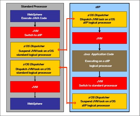
Figure 3-14 Logical flow of Java code execution on a zIIP
A zIIP runs only IBM authorized code. This IBM authorized code includes the z/OS JVM in association with parts of system code, such as the z/OS dispatcher and supervisor services. A zIIP cannot process I/O or clock comparator interruptions, and it does not support operator controls, such as IPL.
Java application code can either run on a CP or a zIIP. The installation can manage the use of CPs so that Java application code runs only on CPs, only on zIIPs, or on both.
Two execution options for zIIP-eligible code execution are available. These options are user-specified in IEAOPTxx, and can be dynamically altered by the SET OPT command. The following options are currently supported for z/OS V1R10 and later releases:
•Option 1: Java dispatching by priority (IIPHONORPRIORITY=YES): This is the default option, and specifies that CPs must not automatically consider zIIP-eligible work for dispatching on them. The zIIP-eligible work is dispatched on the zIIP engines until Workload Manager (WLM) considers that the zIIPs are overcommitted. WLM then requests help from the CPs. When help is requested, the CPs consider dispatching zIIP-eligible work on the CPs themselves based on the dispatching priority relative to other workloads. When the zIIP engines are no longer overcommitted, the CPs stop considering zIIP-eligible work for dispatch.
This option runs as much zIIP-eligible work on zIIPs as possible, and allows it to spill over onto the CPs only when the zIIPs are overcommitted.
•Option 2: Java dispatching by priority (IIPHONORPRIORITY=NO): zIIP-eligible work runs on zIIPs only while at least one zIIP engine is online. zIIP-eligible work is not normally dispatched on a CP, even if the zIIPs are overcommitted and CPs are unused. The exception is that zIIP-eligible work can sometimes run on a CP to resolve resource conflicts.
Therefore, zIIP-eligible work does not affect the CP utilization that is used for reporting through the subcapacity reporting tool (SCRT), no matter how busy the zIIPs are.
If zIIPs are defined to the LPAR but are not online, the zIIP-eligible work units are processed by CPs in order of priority. The system ignores the IIPHONORPRIORITY parameter in this case and handles the work as though it had no eligibility to zIIPs.
zIIPs provide the following benefits:
•Potential cost savings.
•Simplification of infrastructure as a result of the collocation and integration of new applications with their associated database systems and transaction middleware, such as DB2, IMS, or CICS. Simplification can happen, for example, by introducing a uniform security environment, and by reducing the number of TCP/IP programming stacks and system interconnect links.
•Prevention of processing latencies that occur if Java application servers and their database servers are deployed on separate server platforms.
.The following DB2 UDB for z/OS V8 or later workloads are eligible to run in SRB mode:
•Query processing of network-connected applications that access the DB2 database over
a TCP/IP connection by using IBM Distributed Relational Database Architecture (DRDA). DRDA enables relational data to be distributed among multiple systems. It is native to DB2 for z/OS, therefore reducing the need for more gateway products that can affect performance and availability. The application uses the DRDA requester or server to access a remote database. IBM DB2 Connect™ is an example of a DRDA application requester.
a TCP/IP connection by using IBM Distributed Relational Database Architecture (DRDA). DRDA enables relational data to be distributed among multiple systems. It is native to DB2 for z/OS, therefore reducing the need for more gateway products that can affect performance and availability. The application uses the DRDA requester or server to access a remote database. IBM DB2 Connect™ is an example of a DRDA application requester.
•Star schema query processing, mostly used in business intelligence (BI) work. A star schema is a relational database schema for representing multidimensional data. It stores data in a central fact table and is surrounded by more dimension tables that hold information about each perspective of the data. A star schema query, for example, joins various dimensions of a star schema data set.
•DB2 utilities that are used for index maintenance, such as LOAD, REORG, and REBUILD. Indexes allow quick access to table rows, but over time, as data in large databases is manipulated, the databases become less efficient and must be maintained.
The zIIP runs portions of eligible database workloads, and so helps to free computer capacity and lower software costs. Not all DB2 workloads are eligible for zIIP processing. DB2 UDB for z/OS V8 and later gives z/OS the information to direct portions of the work to the zIIP. The result is that in every user situation, different variables determine how much work is redirected to the zIIP.
On a z13, the following workloads can also benefit from zIIPs:
•z/OS Communications Server uses the zIIP for eligible Internet Protocol Security (IPSec) network encryption workloads. This configuration requires z/OS V1R10 or later releases. Portions of IPSec processing take advantage of the zIIPs, specifically end-to-end encryption with IPSec. The IPSec function moves a portion of the processing from the general-purpose processors to the zIIPs. In addition, to run the encryption processing, the zIIP also handles the cryptographic validation of message integrity and IPSec header processing.
•z/OS Global Mirror, formerly known as Extended Remote Copy (XRC), uses the zIIP as well. Most z/OS Data Facility Storage Management Subsystem (DFSMS) system data mover (SDM) processing that is associated with z/OS Global Mirror can run on the zIIP. This configuration requires z/OS V1R10 or later releases.
•The first IBM user of z/OS XML system services is DB2 V9. For DB2 V9 before the z/OS XML System Services enhancement, z/OS XML System Services non-validating parsing was partially directed to zIIPs when used as part of a distributed DB2 request through DRDA. This enhancement benefits DB2 V9 by making all z/OS XML System Services non-validating parsing eligible to zIIPs. This configuration is possible when processing is used as part of any workload that is running in enclave SRB mode.
•z/OS Communications Server also allows the HiperSockets Multiple Write operation for outbound large messages (originating from z/OS) to be run by a zIIP. Application workloads that are based on XML, HTTP, SOAP, and Java, and traditional file transfer, can benefit.
•For business intelligence, IBM Scalable Architecture for Financial Reporting provides a high-volume, high performance reporting solution by running many diverse queries in z/OS batch. It can also be eligible for zIIP.
For more information about zIIP and eligible workloads, see the IBM zIIP website:
zIIP installation information
One CP must be installed with or before any zIIP is installed. In zNext, the zIIP to CP ratio is 2:1, which means that up to 94 zIIPs on a model NE1 can be characterized. Table 3-1 shows the allowed number of zIIPs for each model.
Table 3-1 Number of zIIPs per model
|
Model
|
N30
|
N63
|
N96
|
NC9
|
NE1
|
|
Maximum zIIPs
|
0 - 20
|
0 - 42
|
0 - 64
|
0 - 86
|
0 - 94
|
zIIPs are orderable by using FC 1922. Up to two zIIP can be ordered for each CP or marked CP configured in the system. If the installed CPC drawer has no remaining unassigned PUs, the assignment of the next zIIP might require the installation of an additional CPC drawer.
PUs characterized as zIIPs within a configuration are grouped into the zIIP pool. This configuration allows zIIPs to have their own processing weights, independent of the weight of parent CPs. The zIIP pool can be seen on the hardware console.
The number of permanent zIIPs plus temporary zIIPs cannot exceed twice the number of purchased CPs plus temporary CPs. Also, the number of temporary zIIPs cannot exceed the number of permanent zIIPs.
zIIPs and logical partition definitions
zIIPs are either dedicated or shared depending on whether they are part of an LPAR with dedicated or shared CPs. In an LPAR, at least one CP must be defined before zIIPs for that partition can be defined. The number of zIIPs that are available in the system is the number of zIIPs that can be defined to an LPAR.
|
Logical partition: In a logical partition, as many zIIPs as are available can be defined together with at least one CP.
|
3.5.6 System assist processors
A system assist processor (SAP) is a PU that runs the channel subsystem LIC to control I/O operations. All SAPs run I/O operations for all LPARs. All models have standard SAPs configured. The number of standard SAPs depends on the z13 model, as shown in Table 3-2.
Table 3-2 SAPs per model
|
Model
|
N30
|
N63
|
N96
|
NC9
|
NE1
|
|
Standard SAPs
|
6
|
12
|
18
|
24
|
24
|
SAP configuration
A standard SAP configuration provides a well-balanced system for most environments. However, there are application environments with high I/O rates (typically various Transaction Processing Facility (TPF) environments). In this case, more SAPs can be ordered. Assignment of more SAPs can increase the capability of the channel subsystem to run I/O operations. In z13 systems, the number of SAPs can be greater than the number of CPs. However, additional SAPs plus standard SAPs cannot exceed 32.
Optional additional orderable SAPs
The ability to order more SAPs is an option that is available on all models (FC 1921). These additional SAPs increase the capacity of the channel subsystem to run I/O operations, which is suggested for TPF environments. The maximum number of optional additional orderable SAPs depends on the configuration and the number of available uncharacterized PUs. The number of SAPs is listed in Table 3-3.
Table 3-3 Optional SAPs per model
|
Model
|
N30
|
N63
|
N96
|
NC9
|
NE1
|
|
Optional SAPs
|
0 - 4
|
0 - 8
|
0 - 12
|
0 - 16
|
0 - 16
|
3.5.7 Reserved processors
Reserved processors are defined by the PR/SM to allow for a nondisruptive capacity upgrade. Reserved processors are like spare logical processors, and can be shared or dedicated. Reserved CPs can be defined to an LPAR dynamically to allow for nondisruptive image upgrades.
Reserved processors can be dynamically configured online by an operating system that supports this function, if enough unassigned PUs are available to satisfy this request. The PR/SM rules that govern logical processor activation remain unchanged.
By using reserved processors, you can define to an LPAR more logical processors than the number of available CPs, IFLs, ICFs, zAAPs, and zIIPs in the configuration. This process makes it possible to configure online, nondisruptively, more logical processors after additional CPs, IFLs, ICFs, zAAPs, and zIIPs are made available concurrently. They can be made available with one of the Capacity on Demand options.
The maximum number of reserved processors that can be defined to an LPAR depends on the number of logical processors that already are defined. The maximum number of logical processors plus reserved processors is 141. If the operating system in the LPAR supports the logical processor add function, reserved processors are no longer needed.
Do not define more active and reserved processors than the operating system for the LPAR can support. For more information about logical processors and reserved processors and their definitions, see 3.7, “Logical partitioning” on page 116.
3.5.8 Integrated firmware processor (IFP)
An IFP is allocated from the pool of PUs. This is available for the whole system. Unlike other characterized PUs, the IFP is standard and not defined by the client. It is a single PU dedicated solely to supporting the native Peripheral Component Interconnect Express (PCIe) features (10GbE Remote Direct Memory Access (RDMA) over Converged Ethernet (RoCE) Express and zEnterprise Data Compression (zEDC) Express) and is initialized at POR. The IFP supports Resource Group (RG) LIC to provide native PCIe I/O feature management and virtualization functions. For more information, see Appendix G, “Native Peripheral Component Interconnect Express (PCIe)” on page 527.
3.5.9 Processor unit assignment
The processor unit assignment of characterized PUs is done at POR time, when the system is initialized. The initial assignment rules keep PUs of the same characterization type grouped as much as possible in relation to PU chips and CPC drawer boundaries to optimize shared cache usage.
The PU assignment is based on CPC drawer plug ordering. The CPC drawers are populated from the bottom upward. This process defines the low-order and the high-order CPC drawers:
•CPC drawer 1: Plug order 1 (low-order CPC drawer)
•CPC drawer 2: Plug order 2
•CPC drawer 3: Plug order 3
•CPC drawer 4: Plug order 4 (high-order CPC drawer)
The assignment rules follow this order:
•Spare: CPC drawers 1 and 2 are assigned one spare each on the high PU chip. In the model N30, the two spares are assigned to CPC drawer 1.
•IFP: One IFP is assigned to CPC drawer 1.
•SAPs: Spread across CPC drawers and high PU chips. Each CPC drawer has six standard SAPs. Start with the highest PU chip high core, then the next highest PU chip high core. This prevents all the SAPs from being assigned on one PU chip.
•IFLs and ICFs: Assign IFLs and ICFs to cores on chips in higher CPC drawers working downward.
•CPs and zIIPs: Assign CPs and zIIPs to cores on chips in lower CPC drawers working upward.
These rules are intended to isolate, as much as possible, on different CPC drawers and even on different PU chips, processors that are used by different operating systems. This configuration ensures that different operating systems do not use the same shared caches. For example, CPs and zIIPs are all used by z/OS, and can benefit by using the same shared caches. However, IFLs are used by z/VM and Linux, and ICFs are used by CFCC. Therefore, for performance reasons, the assignment rules prevent them from sharing L3 and L4 caches with z/OS processors.
This initial PU assignment, which is done at POR, can be dynamically rearranged by an LPAR by swapping an active core to a core in a different PU chip in a different CPC drawer or node to improve system performance. For more information, see “LPAR dynamic PU reassignment” on page 122.
When an additional CPC drawer is added concurrently after POR and new LPARs are activated, or processor capacity for active partitions is dynamically expanded, the additional PU capacity can be assigned from the new CPC drawer. The processor unit assignment rules consider the newly installed CPC drawer only after the next POR.
3.5.10 Sparing rules
On a z13 system, two PUs are reserved as spares. The reserved spares are available to replace any two characterized PUs, whether they are CP, IFL, ICF, zIIP, SAP, or IFP.
Systems with a failed PU for which no spare is available will call home for a replacement. A system with a failed PU that is spared and requires an SCM to be replaced (referred to as a pending repair) can still be upgraded when sufficient PUs are available.
Transparent CP, IFL, ICF, zIIP, SAP, and IFP sparing
Depending on the model, sparing of CP, IFL, ICF, zIIP, SAP, and IFP is transparent and does not require operating system or operator intervention.
With transparent sparing, the status of the application that was running on the failed processor is preserved. The application continues processing on a newly assigned CP, IFL, ICF, zIIP, SAP, or IFP (allocated to one of the spare PUs) without client intervention.
Application preservation
If no spare PU is available, application preservation (z/OS only) is started. The state of the failing processor is passed to another active processor that is used by the operating system. Through operating system recovery services, the task is resumed successfully (in most cases, without client intervention).
Dynamic SAP and IFP sparing and reassignment
Dynamic recovery is provided if there is a failure of the SAP or IFP. If the SAP or IFP fails, and if a spare PU is available, the spare PU is dynamically assigned as a new SAP or IFP. If no spare PU is available, and more than one CP is characterized, a characterized CP is reassigned as an SAP or IFP. In either case, client intervention is not required. This capability eliminates an unplanned outage and allows a service action to be deferred to a more convenient time.
3.5.11 Increased flexibility with z/VM mode partitions
z13 provides a capability for the definition of a z/VM mode LPAR that contains a mix of processor types that includes CPs and specialty processors, such as IFLs, zIIPs, and ICFs.
z/VM V5R4 and later support this capability, which increases flexibility and simplifies systems management. In a single LPAR, z/VM can perform these tasks:
•Manage guests that use Linux on z Systems on IFLs, and those that use z/VSE, or z/OS on CPs
•Run designated z/OS workloads, such as Java and XML execution and parts of DB2 DRDA processing, on zIIPs
If the only operating system to run under z/VM is Linux, define a Linux only LPAR.
3.6 Memory design
This section describes various considerations of the z13 memory design.
3.6.1 Overview
The z13 memory design also provides flexibility, high availability, and upgrades:
•Concurrent memory upgrades (if the physically installed capacity is not yet reached): The z13 can have more physically installed memory than the initial available capacity. Memory upgrades within the physically installed capacity can be done concurrently by LIC, and no hardware changes are required. However, memory upgrades cannot be done through CBU or On/Off CoD.
•Concurrent memory upgrades (if the physically installed capacity is reached): Physical memory upgrades require a processor cage to be removed and reinstalled after replacing the memory cards in the processor cage. Except for a model N30, the combination of enhanced drawer availability and the flexible memory option allows you to concurrently add memory to the system. For more information, see 2.4.5, “Drawer replacement and memory” on page 55 and 2.4.6, “Flexible Memory Option” on page 55.
When the total capacity that is installed has more usable memory than required for a configuration, the LIC configuration control (LICCC) determines how much memory is used from each processor drawer. The sum of the LICCC provided memory from each processor drawer is the amount that is available for use in the system.
Memory allocation
Memory assignment or allocation is done at POR when the system is initialized. PR/SM is responsible for the memory assignments.
PR/SM knows the amount of purchased memory and how it relates to the available physical memory in each of the installed processor drawers. PR/SM has control over all physical memory, and so can make physical memory available to the configuration when a processor drawer is nondisruptively added.
In prior z Systems processors, memory allocation was striped across the available processor books because there was relatively fast connectivity between the books, and splitting the work between all of the memory controllers allowed a smooth performance variability.
On z13, the memory allocation algorithm has changed. PR/SM tries to allocate memory in to a single processor drawer, striped between the two nodes. Basically, the PR/SM memory and processor resources allocation goal is to place all partition resources on a single processor drawer, if possible. The resources, memory, and processors are assigned to the partitions when they are activated. Later on, when all partitions are activated, PR/SM can move memory between processor drawers to benefit performance, without OS knowledge. This was done on the previous families of z Systems only for Processor Units that use PR/SM dynamic PU reallocation.
With z13, any time the configuration changes by activating or deactivating a partition, has a change in the partition processing weights, or by upgrading or downgrading the system through a temporary or permanent record, PR/SM schedules a global reoptimization of the resources in use. It does so by looking at all the partitions that are active and prioritizing them based on their processing entitlement and weights, creating a high and low priority rank. Then the resources, such as processors and memory, can be moved from one processor drawer to another to address the priorities ranks just created.
When partitions are activated, PR/SM tries to find a home assignment processor drawer, home assignment node, and home assignment chip for the logical processors that are defined to them. The PR/SM goal is to allocate all the partition logical processors and memory to a single processor drawer (the home drawer for that partition). If all logical processors can be assigned to a home drawer and the partition defined memory is greater than what is available in that drawer, the exceeding memory amount is allocated on another drawer. If all the logical processors cannot fit in one processor drawer, the remaining processors spill to another processor drawer and, when that happens, PRSM stripes the memory, if possible, across the processor drawers where the processors are assigned.
The process of reallocating memory is based on the memory copy/reassign function, which was used to allow enhanced book availability (EBA) and concurrent book replacement (CBR) in previous z Systems families. However, this process has been enhanced to provide more efficiency and speed to the process without affecting system performance. PR/SM controls the reassignment of the content of a specific physical memory array in one processor drawer to a physical memory array in another processor drawer. To do that, PR/SM uses all the available physical memory in the system, including the memory not in use by the system, that is available but not purchased by the client, and the planned and flex memory options, if installed.
Because of the memory allocation algorithm, systems that undergo a number of miscellaneous equipment specification (MES) upgrades for memory can have different memory mixes and quantities in all processor drawers of the system. If the memory fails, it is technically feasible to run a POR of the system with the remaining working memory resources. After the POR completes, the memory distribution across the processor drawers will be different, as will be the total amount of available memory.
Large page support
By default, page frames are allocated with a 4 KB size. The z13 also supports large page sizes of 1 MB or 2 GB. The first z/OS release that supports 1 MB pages is z/OS V1R9. Linux on z Systems support for 1 MB pages is available in SUSE Linux Enterprise Server (SLES) 10 SP2 and Red Hat Enterprise Linux (RHEL) 5.2.
The TLB exists to reduce the amount of time that is required to translate a virtual address to a real address. This translation is done by dynamic address translation (DAT) when it must find the correct page for the correct address space. Each TLB entry represents one page. Like other buffers or caches, lines are discarded from the TLB on a least recently used (LRU) basis. The worst-case translation time occurs when there is a TLB miss and both the segment table (which is needed to find the page table) and the page table (which is needed to find the entry for the particular page in question) are not in cache. In this case, there are two complete real memory access delays plus the address translation delay. The duration of a processor cycle is much shorter than the duration of a memory cycle, so a TLB miss is relatively costly.
It is preferable to have addresses in the TLB. With 4 K pages, holding all the addresses for
1 MB of storage takes 256 TLB lines. When you are using 1 MB pages, it takes only one TLB line. Therefore, large page size users have a much smaller TLB footprint.
1 MB of storage takes 256 TLB lines. When you are using 1 MB pages, it takes only one TLB line. Therefore, large page size users have a much smaller TLB footprint.
Large pages allow the TLB to better represent a large working set and suffer fewer TLB misses by allowing a single TLB entry to cover more address translations.
Users of large pages are better represented in the TLB and are expected to see performance improvements in both elapsed time and processor usage. These improvements are because DAT and memory operations are part of processor busy time even though the processor waits for memory operations to complete without processing anything else in the meantime.
To overcome the processor usage that is associated with creating a 1 MB page, a process must run for some time. It must maintain frequent memory access to keep the pertinent addresses in the TLB.
Short-running work does not overcome the processor usage. Short processes with small working sets are expected to receive little or no improvement. Long-running work with high memory-access frequency is the best candidate to benefit from large pages.
Long-running work with low memory-access frequency is less likely to maintain its entries in the TLB. However, when it does run, a smaller number of address translations is required to resolve all the memory it needs. Therefore, a long-running process can benefit even without frequent memory access. Weigh the benefits of whether something in this category must use large pages as a result of the system-level costs of tying up real storage. There is a balance between the performance of a process using large pages, and the performance of the remaining work on the system.
On z13, 1 MB large pages become pageable if Flash Express is available and enabled. They are available only for 64-bit virtual private storage, such as virtual memory above 2 GB.
It is easy to assume that increasing the TLB size is a feasible option to deal with TLB-miss situations. However, this process is not as straightforward as it seems. As the size of the TLB increases, so does the processor usage that is involved in managing the TLB’s contents. Correct sizing of the TLB is subject to complex statistical modeling to find the optimal tradeoff between size and performance.
3.6.2 Main storage
Main storage is addressable by programs, and storage that is not directly addressable by programs. Non-addressable storage includes the hardware system area (HSA).
Main storage provides these functions:
•Data storage and retrieval for PUs and I/O
•Communication with PUs and I/O
•Communication with and control of optional expanded storage
•Error checking and correction
Main storage can be accessed by all processors, but cannot be shared between LPARs. Any system image (LPAR) must have a main storage size defined. This defined main storage is allocated exclusively to the LPAR during partition activation.
3.6.3 Expanded storage
Expanded storage can optionally be defined on z13. Expanded storage is physically a section of processor storage. It is controlled by the operating system and transfers 4-KB pages to and from main storage.
Storage considerations
Except for z/VM, z/Architecture operating systems do not use expanded storage. Because they operate in 64-bit addressing mode, they can have all the required storage capacity allocated as main storage. z/VM is an exception because even when it operates in 64-bit mode, it can have guest virtual machines that are running in 31-bit addressing mode. The guest systems can use expanded storage. In addition, z/VM uses expanded storage for its own operations.
|
z/VM 6.3: Starting in z/VM 6.3, it is no longer preferable to configure any of the memory as expanded storage unless it is being attached to a virtual machine for testing or some unique purpose. Configure all the processor memory as main storage.
|
Defining expanded storage to a coupling facility image is not possible. However, any other image type can have expanded storage that is defined, even if that image runs a 64-bit operating system and does not use expanded storage.
|
Removal of support for Expanded Storage (XSTORE)1: z/VM V6.3 is the last z/VM release that supports Expanded Storage (XSTORE) for either host or guest use. The IBM z13 server family is the last z Systems server to support Expanded Storage (XSTORE).
|
1 All statements regarding IBM plans, directions, and intent are subject to change or withdrawal without notice. Any reliance on these statements of general direction is at the relying party’s sole risk and will not create liability or obligation for IBM.
The z13 runs only in LPAR mode. Storage is placed into a single storage pool that is called the LPAR single storage pool. This pool can be dynamically converted to expanded storage and back to main storage as needed when partitions are activated or deactivated.
LPAR single storage pool
In LPAR mode, storage is not split into main storage and expanded storage at POR. Rather, the storage is placed into a single main storage pool that is dynamically assigned to expanded storage and back to main storage, as needed.
On the HMC, the storage assignment tab of a reset profile shows the customer storage. Customer storage is the total installed storage. LPARs are still defined to have main storage and, optionally, expanded storage.
Activation of LPARs and dynamic storage reconfiguration cause the storage to be assigned to the type that is needed (central or expanded). It does not require a POR.
3.6.4 Hardware system area (HSA)
The HSA is a non-addressable storage area that contains system LIC and configuration-dependent control blocks. On the z13, the HSA has a fixed size of
96 GB and is not part of the purchased memory that you order and install.
96 GB and is not part of the purchased memory that you order and install.
The fixed size of the HSA eliminates planning for future expansion of the HSA because the hardware configuration definition (HCD)/input/output configuration program (IOCP) always reserves space for the following items:
•Six channel subsystems (CSSs)
•Fifteen LPARs in the five CSSs and 10 LPARs for the sixth CSS for a total of 85 LPARs
•Subchannel set 0 with 63.75-K devices in each CSS
•Subchannel set 1 with 64-K devices in each CSS
•Subchannel set 2 with 64-K devices in each CSS
•Subchannel set 3 with 64-K devices in each CSS
The HSA has sufficient reserved space to allow for dynamic I/O reconfiguration changes to the maximum capability of the processor.
3.7 Logical partitioning
This section addresses logical partitioning features.
3.7.1 Overview
Logical partitioning is a function that is implemented by the PR/SM on the z13. The z13 runs only in LPAR mode. Therefore, all system aspects are controlled by PR/SM functions.
PR/SM is aware of the processor drawer structure on the z13. However, LPARs do not have this awareness. LPARs have resources that are allocated to them from various physical resources. From a systems standpoint, LPARs have no control over these physical resources, but the PR/SM functions do.
PR/SM manages and optimizes allocation and the dispatching of work on the physical topology. Most physical topology that was previously handled by the operating systems is the responsibility of PR/SM.
As shown in 3.5.9, “Processor unit assignment” on page 110, the initial PU assignment is done during POR by using rules to optimize cache usage. This is the “physical” step, where CPs, zIIPs, IFLs, ICFs, and SAPs are allocated on the processor drawers.
When an LPAR is activated, PR/SM builds logical processors and allocates memory for the LPAR.
Memory allocation has changed from the previous z Systems. IBM System z9® memory used to be spread across all books. This optimization was done by using a round-robin algorithm with a number of increments per book to match the number of memory controllers (MCs) per book. This memory allocation design was driven by performance results, which minimized variability for most workloads.
With z13, memory allocation has changed from the model that was used for the z9. Partition memory is now allocated in a per processor drawer basis and striped across processor nodes. For more information, see “Memory allocation” on page 112.
Logical processors are dispatched by PR/SM on physical processors. The assignment topology that is used by PR/SM to dispatch logical processors on physical PUs is also based on cache usage optimization.
Processor drawers and node level assignments are more important because they optimize L4 cache usage. Therefore, logical processors from a specific LPAR are packed into a processor drawer as much as possible.
Then, PR/SM optimizes chip assignments within the assigned processor drawers (or drawers) to maximize L3 cache efficiency. Logical processors from an LPAR are dispatched on physical processors on the same PU chip as much as possible. The number of processors per chip (eight) matches the number of z/OS processor affinity queues that is used by HiperDispatch, achieving optimal cache usage within an affinity node.
PR/SM also tries to redispatch a logical processor on the same physical processor to optimize private cache (L1 and L2) usage.
|
Removal of an option for the way shared logical processors are managed under PR/SM LPAR1: IBM z13 will be the last high-end server to support selection of the option to "Do not end the time slice if a partition enters a wait state" when the option to set a processor runtime value has been previously selected in the CPC RESET profile. The CPC RESET profile applies to all shared logical partitions on the system, and is not selectable by logical partition.
|
1 All statements regarding IBM plans, directions, and intent are subject to change or withdrawal without notice. Any reliance on these statements of general direction is at the relying party’s sole risk and will not create liability or obligation for IBM.
HiperDispatch
PR/SM and z/OS work in tandem to use processor resources more efficiently. HiperDispatch is a function that combines the dispatcher actions and the knowledge that PR/SM has about the topology of the system.
Performance can be optimized by redispatching units of work to the same processor group, keeping processes running near their cached instructions and data, and minimizing transfers of data ownership among processors and processor drawers.
The nested topology is returned to z/OS by the Store System Information (STSI) instruction. HiperDispatch uses the information to concentrate logical processors around shared caches (L3 at PU chip level, and L4 at book level), and dynamically optimizes the assignment of logical processors and units of work.
z/OS dispatcher manages multiple queues, called affinity queues, with a target number of eight processors per queue, which fits nicely onto a single PU chip. These queues are used to assign work to as few logical processors as are needed for an LPAR workload. So, even if the LPAR is defined with many logical processors, HiperDispatch optimizes this number of processors to be near the required capacity. The optimal number of processors to be used is kept within a processor drawer boundary where possible.
|
Tip: HiperDispatch is now also supported by z/VM V6.3.
|
Logical partitions (LPARs)
PR/SM enables the z13 to be initialized for a logically partitioned operation, supporting up to 85 LPARs. Each LPAR can run its own operating system image in any image mode, independently from the other LPARs.
An LPAR can be added, removed, activated, or deactivated at any time. Changing the number of LPARs is not disruptive and does not require POR. Certain facilities might not be available to all operating systems because the facilities might have software corequisites.
Each LPAR has the same resources as a real CPC:
•Processors: Called logical processors, they can be defined as CPs, IFLs, ICFs, or zIIPs. They can be dedicated to an LPAR or shared among LPARs. When shared, a processor weight can be defined to provide the required level of processor resources to an LPAR. Also, the capping option can be turned on, which prevents an LPAR from acquiring more than its defined weight, limiting its processor consumption.
LPARs for z/OS can have CP and zIIP logical processors. The two logical processor types can be defined as either all dedicated or all shared. The zIIP support is available in z/OS.
The weight and number of online logical processors of an LPAR can be dynamically managed by the LPAR CPU Management function of the Intelligent Resource Director (IRD). These can be used to achieve the defined goals of this specific partition and of the overall system. The provisioning architecture of the z13, described in Chapter 8, “System upgrades” on page 307, adds another dimension to the dynamic management of LPARs.
PR/SM is enhanced to support an option to limit the amount of physical processor capacity that is consumed by an individual LPAR when a PU is defined as a general-purpose processor (CP) or an IFL shared across a set of LPARs.
This enhancement is designed to provide a physical capacity limit that is enforced as an absolute (versus relative) limit. It is not affected by changes to the logical or physical configuration of the system. This physical capacity limit can be specified in units of CPs or IFLs. The “Change LPAR Controls” and “Customize Activation Profiles” tasks on the Hardware Management Console have been enhanced to support this new function.
For the z/OS Workload License Charges (WLC) pricing metric, and metrics that are based on it, such as Advanced Workload License Charges (AWLC), an LPAR defined capacity can be set. This defined capacity enables the soft capping function. Workload charging introduces the capability to pay software license fees based on the processor utilization of the LPAR on which the product is running, rather than on the total capacity of the system:
– In support of WLC, the user can specify a defined capacity in millions of service units (MSUs) per hour. The defined capacity sets the capacity of an individual LPAR when soft capping is selected.
The defined capacity value is specified on the Options tab in the Customize Image Profiles window.
– WLM keeps a 4-hour rolling average of the processor usage of the LPAR. When the 4-hour average processor consumption exceeds the defined capacity limit, WLM dynamically activates LPAR capping (soft capping). When the rolling 4-hour average returns below the defined capacity, the soft cap is removed.
For more information about WLM, see System Programmer's Guide to: Workload Manager, SG24-6472. For a review of software licensing, see 7.16.1, “Software licensing considerations” on page 299.
|
Weight settings: When defined capacity is used to define an uncapped LPAR’s capacity, carefully consider the weight settings of that LPAR. If the weight is much smaller than the defined capacity, PR/SM uses a discontinuous cap pattern to achieve the defined capacity setting. This configuration means PR/SM alternates between capping the LPAR at the MSU value corresponding to the relative weight settings, and no capping at all. It is best to avoid this scenario, and try to establish a defined capacity that is equal or close to the relative weight.
|
•Memory: Memory, either main storage or expanded storage, must be dedicated to an LPAR. The defined storage must be available during the LPAR activation. Otherwise, the LPAR activation fails.
Reserved storage can be defined to an LPAR, enabling nondisruptive memory addition to and removal from an LPAR, by using the LPAR dynamic storage reconfiguration (z/OS and z/VM). For more information, see 3.7.5, “LPAR dynamic storage reconfiguration” on page 127.
•Channels: Channels can be shared between LPARs by including the partition name in the partition list of a channel-path identifier (CHPID). I/O configurations are defined by the IOCP or the HCD with the CHPID mapping tool (CMT). The CMT is an optional tool that is used to map CHPIDs onto physical channel IDs (PCHIDs). PCHIDs represent the physical location of a port on a card in an I/O cage, I/O drawer, or PCIe I/O drawer.
IOCP is available on the z/OS, z/VM, and z/VSE operating systems, and as a stand-alone program on the hardware console. HCD is available on the z/OS and z/VM operating systems.
Fibre Channel connection (FICON) channels can be managed by the Dynamic CHPID Management (DCM) function of the Intelligent Resource Director. DCM enables the system to respond to ever-changing channel requirements by moving channels from lesser-used control units to more heavily used control units, as needed.
Modes of operation
Table 3-4 shows the nodes of operation, summarizing all available mode combinations, including their operating modes and processor types, operating systems, and addressing modes. Only the currently supported versions of operating systems are considered.
Table 3-4 z13 modes of operation
|
Image mode
|
PU type
|
Operating system
|
Addressing mode
|
|
ESA/390
|
CP and zIIP
|
z/OS
z/VM
|
64-bit
|
|
CP
|
z/VSE and Linux on z Systems (64-bit)
|
64-bit
|
|
|
CP
|
Linux on z Systems (31-bit)
|
31-bit
|
|
|
ESA/390 TPF
|
CP only
|
z/TPF
|
64-bit
|
|
Coupling facility
|
ICF or CP
|
CFCC
|
64-bit
|
|
Linux only
|
IFL or CP
|
Linux on z Systems (64-bit)
|
64-bit
|
|
z/VM
|
|||
|
Linux on z Systems (31-bit)
|
31-bit
|
||
|
z/VM
|
CP, IFL, zIIP, or ICF
|
z/VM
|
64-bit
|
|
zAware
|
IFL or CP
|
IBM zAware
|
64-bit
|
The 64-bit z/Architecture mode has no special operating mode because the architecture mode is not an attribute of the definable images operating mode. The 64-bit operating systems are in 31-bit mode at IPL and, optionally, can change to 64-bit mode during their initialization. The operating system is responsible for taking advantage of the addressing capabilities that are provided by the architectural mode.
For information about operating system support, see Chapter 7, “Software support” on page 227.
Logically partitioned mode
The z13 runs only in LPAR mode. Each of the 85 LPARs can be defined to operate in one of the following image modes:
•ESA/390 mode to run the following systems:
– A z/Architecture operating system, on dedicated or shared CPs
– An ESA/390 operating system, on dedicated or shared CPs
– A Linux on z Systems operating system, on dedicated or shared CPs
– z/OS, on any of the following processor units:
• Dedicated or shared CPs
• Dedicated CPs and dedicated zIIPs
• Shared CPs and shared zIIPs
|
zIIP usage: zIIPs can be defined to an ESA/390 mode or z/VM mode image, as shown in Table 3-4 on page 119. However, zIIPs are used only by z/OS. Other operating systems cannot use zIIPs even if they are defined to the LPAR. z/VM V5R41 and later provide support for real and virtual zIIPs to guest z/OS systems.
|
1 z/VM V5R4 is not supported on IBM z13
•ESA/390 TPF mode to run the z/TPF operating system, on dedicated or shared CPs
•Coupling facility mode, by loading the CFCC code into the LPAR that is defined as one of these types:
– Dedicated or shared CPs
– Dedicated or shared ICFs
•Linux only mode to run these systems:
– A Linux on z Systems operating system, on either of these types:
• Dedicated or shared IFLs
• Dedicated or shared CPs
– A z/VM operating system, on either of these types:
• Dedicated or shared IFLs
• Dedicated or shared CPs
•z/VM mode to run z/VM on dedicated or shared CPs or IFLs, plus zIIPs and ICFs
•zAware mode to run by loading the IBM zAware code into the LPAR that is defined as either of these types:
– Dedicated or shared CPs
– Dedicated or shared IFLs
Table 3-5 shows all LPAR modes, required characterized PUs, operating systems, and the PU characterizations that can be configured to an LPAR image. The available combinations of dedicated (DED) and shared (SHR) processors are also shown. For all combinations, an LPAR also can have reserved processors that are defined, allowing nondisruptive LPAR upgrades.
Table 3-5 LPAR mode and PU usage
|
LPAR mode
|
PU type
|
Operating systems
|
PUs usage
|
|
ESA/390
|
CPs
|
z/Architecture operating systems
ESA/390 operating systems
Linux on z Systems
|
CPs DED or CPs SHR
|
|
CPs and zIIPs
|
z/OS
z/VM (V6R2 and later for guest exploitation)
|
CPs DED and (or) zIIPs DED or
CPs SHR and (or) zIIPs SHR
|
|
|
ESA/390 TPF
|
CPs
|
z/TPF
|
CPs DED or CPs SHR
|
|
Coupling
facility
|
ICFs or
CPs
|
CFCC
|
ICFs DED or ICFs SHR, or
CPs DED or CPs SHR
|
|
Linux only
|
IFLs or CPs
|
Linux on z Systems
z/VM
|
IFLs DED or IFLs SHR, or
CPs DED or CPs SHR
|
|
z/VM
|
CPs, IFLs, zIIPs, or ICFs
|
z/VM (V6R2 and later)
|
All PUs must be SHR or DED
|
|
zAware
|
IFLs, or CPs
|
IBM zAware
|
IFLs DED or IFLs SHR, or
CPs DED or CPs SHR
|
Dynamically adding or deleting a logical partition name
Dynamically adding or deleting an LPAR name is the ability to add or delete LPARs and their associated I/O resources to or from the configuration without a POR.
The extra channel subsystem and multiple image facility (MIF) image ID pairs (CSSID/MIFID) can be later assigned to an LPAR for use (or later removed). This process can be done through dynamic I/O commands by using HCD. At the same time, required channels must be defined for the new LPAR.
|
Partition profile: Cryptographic coprocessors are not tied to partition numbers or MIF IDs. They are set up with Adjunct Processor (AP) numbers and domain indexes. These are assigned to a partition profile of a given name. The client assigns these AP numbers and domains to the partitions and continues to have the responsibility to clear them out when their profiles change.
|
Adding logical processors to a logical partition
Logical processors can be concurrently added to an LPAR by defining them as reserved in the image profile and later configuring them online to the operating system by using the appropriate console commands. Logical processors also can be concurrently added to a logical partition dynamically by using the Support Element “Logical Processor Add” function under the “CPC Operational Customization” task. This SE function allows the initial and reserved processor values to be dynamically changed. The operating system must support the dynamic addition of these resources. In z/OS, this support is available since Version 1 Release 10 (z/OS V1.10) or later.
Adding a crypto feature to a logical partition
You can plan the addition of Crypto Express5S features to an LPAR on the crypto page in the image profile by defining the Cryptographic Candidate List, and the Usage and Control Domain indexes, in the partition profile. By using the “Change LPAR Cryptographic Controls” task, you can add crypto adapters dynamically to an LPAR without an outage of the LPAR. Also, dynamic deletion or moving of these features does not require pre-planning. Support is provided in z/OS, z/VM, z/VSE, and Linux on z Systems.
LPAR dynamic PU reassignment
The system configuration is enhanced to optimize the PU-to-CPC drawer assignment of physical processors dynamically. The initial assignment of client-usable physical processors to physical processor drawers can change dynamically to better suit the actual LPAR configurations that are in use. For more information, see 3.5.9, “Processor unit assignment” on page 110. Swapping of specialty engines and general processors with each other, with spare PUs, or with both, can occur as the system attempts to compact LPAR configurations into physical configurations that span the least number of processor drawers.
LPAR dynamic PU reassignment can swap client processors of different types between processor drawers. For example, reassignment can swap an IFL on processor drawer 1 with a CP on processor drawer 2. Swaps can also occur between PU chips within a processor drawer or a node and can include spare PUs. The goals are to pack the LPAR on fewer processor drawers and also on fewer PU chips, based on the z13 processor drawers’ topology. The effect of this process is evident in dedicated and shared LPARs that use HiperDispatch.
LPAR dynamic PU reassignment is transparent to operating systems.
LPAR group capacity limit
The group capacity limit feature allows the definition of a group of LPARs on a z13 system, and limits the combined capacity usage by those LPARs. This process allows the system to manage the group so that the group capacity limits in MSUs per hour are not exceeded. To take advantage of this feature, you must be running z/OS V1.10 or later in the all LPARs in the group.
PR/SM and WLM work together to enforce the capacity that is defined for the group and the capacity that is optionally defined for each individual LPAR.
LPAR absolute capping
Absolute capping is a new logical partition control that was made available with zEC12 and is supported on z13. With this support, PR/SM and the HMC are enhanced to support a new option to limit the amount of physical processor capacity that is consumed by an individual LPAR when a PU is defined as a general-purpose processor (CP), zIIP, or an IFL processor that is shared across a set of LPARs.
Unlike traditional LPAR capping, absolute capping is designed to provide a physical capacity limit that is enforced as an absolute (versus relative) value that is not affected by changes to the virtual or physical configuration of the system.
Absolute capping provides an optional maximum capacity setting for logical partitions that is specified in the absolute processors capacity (for example, 5.00 CPs or 2.75 IFLs). This setting is specified independently by processor type (namely CPs, zIIPs, and IFLs) and provides an enforceable upper limit on the amount of the specified processor type that can be used in a partition.
Absolute capping is ideal for processor types and operating systems that the z/OS WLM cannot control. Absolute capping is not intended as a replacement for defined capacity or group capacity for z/OS, which are managed by WLM.
Absolute capping can be used with any z/OS, z/VM, or Linux on z LPAR running on zEnterprise. If specified for a z/OS LPAR, it can be used concurrently with defined capacity or group capacity management for z/OS. When used concurrently, the absolute capacity limit becomes effective before other capping controls.
3.7.2 Storage operations
In the z13, memory can be assigned as a combination of main storage and expanded storage, supporting up to 85 LPARs. Expanded storage is used only by the z/VM operating system.
|
Removal of support for Expanded Storage (XSTORE)1: z/VM V6.3 is the last z/VM release that supports Expanded Storage (XSTORE) for either host or guest use. The IBM z13 server family is the last z Systems server to support Expanded Storage (XSTORE).
|
1 All statements regarding IBM plans, directions, and intent are subject to change or withdrawal without notice. Any reliance on these statements of general direction is at the relying party’s sole risk and will not create liability or obligation for IBM.
Before you activate an LPAR, main storage (and optionally, expanded storage) must be defined to the LPAR. All installed storage can be configured as main storage. Each z/OS individual LPAR can be defined with a maximum of 4 TB of main storage. z/VM supports 1 TB of main storage.
Main storage can be dynamically assigned to expanded storage and back to main storage as needed without a POR. For more information, see “LPAR single storage pool” on page 115.
Memory cannot be shared between system images. It is possible to reallocate dynamically storage resources for z/Architecture LPARs that run operating systems that support dynamic storage reconfiguration (DSR). This process is supported by z/OS, and z/VM V5R4 and later releases. z/VM, in turn, virtualizes this support to its guests. For more information, see 3.7.5, “LPAR dynamic storage reconfiguration” on page 127.
Operating systems that run as guests of z/VM can use the z/VM capability of implementing virtual memory to guest virtual machines. The z/VM dedicated real storage can be shared between guest operating systems.
Table 3-6 shows the z13 storage allocation and usage possibilities, depending on the image mode.
Table 3-6 Main storage definition and usage possibilities
|
Image mode
|
Architecture mode
(addressability)
|
Maximum main storage
|
Expanded storage
|
||
|
Architecture
|
z13
definition
|
z13 definable
|
Operating system usage1
|
||
|
ESA/390
|
z/Architecture (64-bit)
|
16 EB
|
4 TB
|
Yes
|
Yes
|
|
ESA/390 (31-bit)
|
2 GB
|
128 GB
|
Yes
|
Yes
|
|
|
ESA/390 TPF
|
ESA/390 (31-bit)
|
2 GB
|
2 GB
|
Yes
|
No
|
|
Coupling facility
|
CFCC (64-bit)
|
1.5 TB
|
1 TB
|
No
|
No
|
|
Linux only
|
z/Architecture (64-bit)
|
16 EB
|
1 TB
|
Yes
|
Only by z/VM
|
|
ESA/390 (31-bit)
|
2 GB
|
2 GB
|
Yes
|
Only by z/VM
|
|
|
z/VM2
|
z/Architecture (64-bit)
|
16 EB
|
1 TB
|
Yes
|
Yes
|
|
zAware
|
zAware (64-bit)
|
16 EB
|
1 TB
|
Yes
|
No
|
1 z/VM supports the use of expanded storage, but expanded storage is not recommended for z/VM V6.3.
2 z/VM mode is supported by z/VM V6R2 and later.
ESA/390 mode
In ESA/390 mode, storage addressing can be 31 or 64 bits, depending on the operating system architecture and the operating system configuration.
An ESA/390 mode image is always initiated in 31-bit addressing mode. During its initialization, a z/Architecture operating system can change it to 64-bit addressing mode and operate in the z/Architecture mode.
Certain z/Architecture operating systems, such as z/OS, always change the 31-bit addressing mode and operate in 64-bit mode. Other z/Architecture operating systems, such as z/VM, can be configured to change to 64-bit mode or to stay in 31-bit mode and operate in the ESA/390 architecture mode.
The following modes are provided:
•z/Architecture mode: In z/Architecture mode, storage addressing is 64-bit, allowing for virtual addresses up to 16 exabytes (16 EB). The 64-bit architecture theoretically allows a maximum of 16 EB to be used as main storage. However, the current main storage limit for LPARs is 10 TB of main storage. The operating system that runs in z/Architecture mode must be able to support the real storage. Currently, z/OS supports up to 4 TB6 of real storage (z/OS V1R10 and later releases).
Expanded storage also can be configured to an image that runs an operating system in z/Architecture mode. However, only z/VM can use expanded storage. Any other operating system that runs in z/Architecture mode (such as a z/OS or a Linux on z Systems image) does not address the configured expanded storage. This expanded storage remains configured to this image and is unused.
•ESA/390 architecture mode: In ESA/390 architecture mode, storage addressing is 31 bit, allowing for virtual addresses up to 2 GB. A maximum of 2 GB can be used for main storage. Because the processor storage can be configured as central and expanded storage, memory above 2 GB can be configured as expanded storage. In addition, this mode allows the use of either 24-bit or 31-bit addressing, under program control.
Because an ESA/390 mode image can be defined with up to 128 GB of main storage, the main storage above 2 GB is not used. Instead, it remains configured to this image.
|
Storage resources: Either a z/Architecture mode or an ESA/390 architecture mode operating system can run in an ESA/390 image on a z13. Any ESA/390 image can be defined with more than 2 GB of main storage, and can have expanded storage. These options allow you to configure more storage resources than the operating system can address.
|
ESA/390 TPF mode
In ESA/390 TPF mode, storage addressing follows the ESA/390 architecture mode. The z/TPF operating system runs in 64-bit addressing mode.
Coupling facility mode
In coupling facility mode, storage addressing is 64 bit for a coupling facility image that runs at CFCC Level 12 or later. This configuration allows for an addressing range up to 16 EB. However, the current z13 definition limit for LPARs is 1 TB of storage.
CFCC Level 20, which is available for the z13 with driver level 22, introduces several enhancements in the performance, reporting, and serviceability areas.
CFCC Level 19, which is available for the zEC12 with driver level 15F, introduces several improvements in the performance and resiliency areas, including Coupling Thin Interrupts and Flash Express.
For more information, see 3.9.1, “Coupling Facility Control Code” on page 130. Expanded storage cannot be defined for a coupling facility image. Only IBM CFCC can run in the coupling facility mode.
Linux only mode
In Linux only mode, storage addressing can be 31 bit or 64 bit, depending on the operating system architecture and the operating system configuration, in the same way as in ESA/390 mode.
Only Linux and z/VM operating systems can run in Linux only mode. Linux on z Systems 64-bit distributions (SUSE SLES 10 and later, and Red Hat RHEL 5 and later) use 64-bit addressing and operate in z/Architecture mode. z/VM also uses 64-bit addressing and operates in z/Architecture mode.
z/VM mode
In z/VM mode, certain types of processor units can be defined within one LPAR. This increases flexibility and simplifies systems management by allowing z/VM to run the following tasks in the same z/VM LPAR:
•Manage guests to operate Linux on z Systems on IFLs
•Operate z/VSE and z/OS on CPs
•Offload z/OS system software processor usage, such as DB2 workloads on zIIPs
•Provide an economical Java execution environment under z/OS on zAAPs or on zIIPs
zAware mode
In zAware mode, storage addressing is 64 bit for a IBM zAware image that runs IBM z Advanced Workload Analysis Reporter firmware. This configuration allows for an addressing range up to 16 EB. However, the current z13 definition limit for LPARs is 10 TB of storage.
The IBM zAware feature, which is available on z13, zEC12, and zBC12, allows the following capabilities:
•Helps detect and diagnose unusual behavior of z/OS images in near real-time
•Reduces problem determination time and improves service availability beyond standard z/OS features
•Provides an easy-to-use graphical user interface with quick drill-down capabilities to view analytical data about z/OS behavior
For more information, see Appendix A, “IBM z Advanced Workload Analysis Reporter (IBM zAware)” on page 467. Only IBM zAware firmware can run in IBM zAware mode.
3.7.3 Reserved storage
Reserved storage can be optionally defined to an LPAR, allowing a nondisruptive image memory upgrade for this partition. Reserved storage can be defined to both central and expanded storage, and to any image mode except coupling facility mode.
An LPAR must define an amount of main storage and, optionally (if not a coupling facility image), an amount of expanded storage. Both main storage and expanded storage can have two storage sizes defined:
•The initial value is the storage size that is allocated to the partition when it is activated.
•The reserved value is an additional storage capacity beyond its initial storage size that an LPAR can acquire dynamically. The reserved storage sizes that are defined to an LPAR do not have to be available when the partition is activated. They are simply predefined storage sizes to allow a storage increase, from an LPAR point of view.
Without the reserved storage definition, an LPAR storage upgrade is a disruptive process that requires the following actions:
1. Partition deactivation
2. An initial storage size definition change
3. Partition activation
The additional storage capacity for an LPAR upgrade can come from these sources:
•Any unused available storage
•Another partition that has released storage
•A memory upgrade
A concurrent LPAR storage upgrade uses DSR. z/OS uses the reconfigurable storage unit (RSU) definition to add or remove storage units in a nondisruptive way.
z/VM V5R4 and later releases support the dynamic addition of memory to a running LPAR by using reserved storage. It also virtualizes this support to its guests. Removal of storage from the guests or z/VM is disruptive.
SLES 11 supports both concurrent add and remove.
3.7.4 Logical partition storage granularity
Granularity of main storage for an LPAR depends on the largest main storage amount that is defined for either initial or reserved main storage, as shown in Table 3-7.
Table 3-7 Logical partition main storage granularity
|
Logical partition:
Largest main storage amount
|
Logical partition:
Main storage granularity
|
|
Main storage amount <= 256 GB
|
512 MB
|
|
256 GB < main storage amount <= 512 GB
|
1 GB
|
|
512 GB < main storage amount <= 1 TB
|
2 GB
|
|
1 TB < main storage amount <= 2 TB
|
4 GB
|
|
2 TB < main storage amount <= 4 TB
|
8 GB
|
|
4 TB < main storage amount <= 8 TB
|
16 GB
|
|
8 TB < main storage amount <= 10 TB
|
32 GB
|
The granularity applies across all main storage that is defined, both initial and reserved. For example, for an LPAR with an initial storage amount of 30 GB and a reserved storage amount of 48 GB, the main storage granularity of both initial and reserved main storage is 512 MB.
Expanded storage granularity is fixed at 512 MB.
|
Removal of support for Expanded Storage (XSTORE)1: The IBM z13 server family is the last z Systems server to support Expanded Storage (XSTORE).
|
1 All statements regarding IBM plans, directions, and intent are subject to change or withdrawal without notice. Any reliance on these statements of general direction is at the relying party’s sole risk and will not create liability or obligation for IBM.
LPAR storage granularity information is required for LPAR image setup and for z/OS RSU definition. LPARs are limited to a maximum size of 10 TB of main storage. For z/VM V6R2, the limit is 256 GB, while for z/VM V6.3 the limit is 1 TB.
3.7.5 LPAR dynamic storage reconfiguration
Dynamic storage reconfiguration on the z13 allows an operating system running on an LPAR to add (nondisruptively) its reserved storage amount to its configuration. This process can occur only if unused storage exists. This unused storage can be obtained when another LPAR releases storage, or when a concurrent memory upgrade takes place.
With dynamic storage reconfiguration, the unused storage does not have to be continuous.
When an operating system running on an LPAR assigns a storage increment to its configuration, PR/SM determines whether any free storage increments are available. PR/SM then dynamically brings the storage online.
PR/SM dynamically takes offline a storage increment and makes it available to other partitions when an operating system running on an LPAR releases a storage increment.
3.8 Intelligent Resource Director (IRD)
IRD is a z13 and z Systems capability that is used only by z/OS. IRD is a function that optimizes processor and channel resource utilization across LPARs within a single z Systems server.
This feature extends the concept of goal-oriented resource management. It does so by grouping system images that are on the same z13 or z Systems running in LPAR mode, and in the same Parallel Sysplex, into an LPAR cluster. This configuration allows WLM to manage resources, both processor and I/O, not just in one single image, but across the entire cluster of system images.
Figure 3-15 shows an LPAR cluster. It contains three z/OS images, and one Linux image that is managed by the cluster. Included as part of the entire Parallel Sysplex is another z/OS image and a coupling facility image. In this example, the scope over which IRD has control is the defined LPAR cluster.

Figure 3-15 IRD LPAR cluster example
IRD has the following characteristics:
•IRD processor management: WLM dynamically adjusts the number of logical processors within an LPAR and the processor weight based on the WLM policy. The ability to move the processor weights across an LPAR cluster provides processing power where it is most needed, based on WLM goal mode policy.
The processor management function is automatically deactivated when HiperDispatch is active. However, the LPAR weight management function remains active with IRD with HiperDispatch. For more information about HiperDispatch, see 3.7, “Logical partitioning” on page 116.
HiperDispatch manages the number of logical CPs in use. It adjusts the number of logical processors within an LPAR to achieve the optimal balance between CP resources and the requirements of the workload.
HiperDispatch also adjusts the number of logical processors. The goal is to map the logical processor to as few physical processors as possible. This configuration uses the processor resources more efficiently by trying to stay within the local cache structure. Doing so makes efficient use of the advantages of the high-frequency microprocessors, and improves throughput and response times.
•Dynamic channel path management (DCM): DCM moves FICON channel bandwidth between disk control units to address current processing needs. The z13 supports DCM within a channel subsystem.
•Channel subsystem priority queuing: This function on the z13 and z Systems allows the priority queuing of I/O requests in the channel subsystem and the specification of relative priority among LPARs. When running in goal mode, WLM sets the priority for an LPAR and coordinates this activity among clustered LPARs.
For more information about implementing LPAR processor management under IRD, see z/OS Intelligent Resource Director, SG24-5952.
3.9 Clustering technology
Parallel Sysplex is the clustering technology that is used with z13. Figure 3-16 illustrates the components of a Parallel Sysplex as implemented within the z Systems architecture. The figure is intended only as an example. It shows one of many possible Parallel Sysplex configurations.

Figure 3-16 Sysplex hardware overview
Figure 3-16 shows a z13 system that contains multiple z/OS sysplex partitions. It contains an internal coupling facility (CF02), a z13 system that contains a stand-alone CF (CF01), and a zEC12 that contains multiple z/OS sysplex partitions. STP over coupling links provides time synchronization to all systems. The appropriate CF link technology (ICA SR, 1x IFB, or 12x IFB) selection depends on the system configuration and how distant they are physically. The ISC-3 coupling link is not supported on z13. For more information about link technologies, see 4.9.1, “Coupling links” on page 169.
Parallel Sysplex technology is an enabling technology, allowing highly reliable, redundant, and robust z Systems technology to achieve near-continuous availability. A Parallel Sysplex makes up one or more (z/OS) operating system images that are coupled through one or more Coupling Facilities. The images can be combined together to form clusters.
A correctly configured Parallel Sysplex cluster maximizes availability in these ways:
•Continuous (application) availability: Changes can be introduced, such as software upgrades, one image at a time, while the remaining images continue to process work. For more information, see Parallel Sysplex Application Considerations, SG24-6523.
•High capacity: Scales can be 2 - 32 images.
•Dynamic workload balancing: Because it is viewed as a single logical resource, work can be directed to any similar operating system image in a Parallel Sysplex cluster that has available capacity.
•Systems management: The architecture provides the infrastructure to satisfy client requirements for continuous availability, and provides techniques for achieving simplified systems management consistent with this requirement.
•Resource sharing: A number of base (z/OS) components use the coupling facility shared storage. This configuration enables sharing of physical resources with significant improvements in cost, performance, and simplified systems management.
•Single system image: The collection of system images in the Parallel Sysplex is displayed as a single entity to the operator, the user, and the database administrator. A single system image ensures reduced complexity from both operational and definition perspectives.
•N-2 support: Multiple hardware generations (normally three) are supported in the same Parallel Sysplex. This configuration provides for a gradual evolution of the systems in the Parallel Sysplex without having to change all of them simultaneously. Similarly, software support for multiple releases or versions is supported.
Through state-of-the-art cluster technology, the power of multiple images can be harnessed to work in concert on common workloads. The z Systems Parallel Sysplex cluster takes the commercial strengths of the platform to improved levels of system management, competitive price for performance, scalable growth, and continuous availability.
3.9.1 Coupling Facility Control Code
The LPAR running the Coupling Facility Control Code (CFCC) can be on z13, zEC12, zBC12, z196, or z114 systems. For more information about CFCC requirements for supported systems see 7.8, “Coupling facility and CFCC considerations” on page 288.
|
Consideration: z13 cannot coexist in the same sysplex with System z10 and previous systems. The introduction of z13 into existing installations might require more planning.
|
CFCC Level 20
CFCC level 20 is delivered on the z13 with driver level 22. CFCC Level 20 introduces the following enhancements:
•Support for up to 141 ICF processors
– The maximum number of logical processors in a Coupling Facility Partition remains at 16.
•Large memory support
– Improve availability for larger CF cache structures and data sharing performance with larger DB2 group buffer pools (GBPs).
– This support removes inhibitors to using large CF structures, enabling the use of Large Memory to scale to larger DB2 local buffer pools (LBPs) and GBPs in data sharing environments.
– CF structure size remains at a maximum of 1 TB.
•Support for new IBM Integrated Coupling Adapter (ICA)
|
Note: At the time of writing, IBM plans to support up to 256 Coupling CHPIDs on z13 short, that is, twice the 128 coupling CHPIDs supported on zEC12. Each CF image will continue to support a maximum of 128 coupling CHPIDs.
|
z13 systems with CFCC Level 20 require z/OS V1R12 or later, and z/VM V6R2 or later for guest virtual coupling.
To support an upgrade from one CFCC level to the next, different levels of CFCC can be run concurrently while the coupling facility LPARs are running on different servers. CF LPARs that run on the same server share the CFCC level. The CFCC level for z13 servers is CFCC Level 20.
z13 (CFCC level 20) can coexist in a sysplex with CFCC levels 17 and 19.
The CFCC is implemented by using the active wait technique. This technique means that the CFCC is always running (processing or searching for service) and never enters a wait state. This also means that the CF Control Code uses all the processor capacity (cycles) that are available for the coupling facility LPAR. If the LPAR running the CFCC has only dedicated processors (CPs or ICFs), using all processor capacity (cycles) is not a problem. However, this configuration can be an issue if the LPAR that is running the CFCC also has shared processors. Therefore, enable dynamic dispatching on the CF LPAR. With CFCC Level 19 and Coupling Thin Interrupts, shared-processor CF can provide more consistent CF service time and acceptable usage in a broader range of configurations. For more information, see 3.9.3, “Dynamic CF dispatching” on page 132.
|
Performance consideration: Dedicated processor CF still provides the best CF image performance for production environments.
|
CF structure sizing changes are expected when going from CFCC Level 17 (or earlier) to CFCC Level 20. Review the CF structure size by using the CFSizer tool, which is available at this website:
For latest recommended levels, see the current exception letter that is published on Resource Link at the following website:
3.9.2 Coupling Thin Interrupts
CFCC Level 19 introduced Coupling Thin Interrupts to improve performance in environments that share Coupling Facility engines. Although dedicated engines are preferable to obtain the best Coupling Facility performance, Coupling Thin Interrupts can help facilitate the use of a shared pool of engines, helping to lower hardware acquisition costs.
•The interrupt causes a shared logical processor coupling facility partition to be dispatched by PR/SM, if it is not already dispatched, allowing the request or signal to be processed in a more timely manner. The coupling facility gives up control when work is exhausted or when PR/SM takes the physical processor away from the logical processor.
•The use of Coupling Thin Interrupts is controlled by the new DYNDISP specification.
You can experience CF response time improvements or more consistent CF response time when using Coupling Facilities with shared engines. This also can allow more environments with multiple CF images to coexist in a server, and share CF engines with reasonable performance. The response time for asynchronous CF requests can also be improved as a result of using Coupling Thin Interrupts on the z/OS host system, regardless of whether the CF is using shared or dedicated engines.
3.9.3 Dynamic CF dispatching
Dynamic CF dispatching provides the following functions on a coupling facility:
1. If there is no work to do, CF enters a wait state (by time).
2. After an elapsed time, CF wakes up to see whether there is any new work to do (that is, there are requests in the CF Receiver buffer).
3. If there is no work, CF sleeps again for a longer period.
4. If there is new work, CF enters the normal active wait until there is no more work. After all work is complete, the process starts again.
With the introduction of the Coupling Thin Interrupt support, which is used only when the CF partition is using shared engines and the new DYNDISP=THININTERRUPT parameter, the CFCC code is changed to handle these interrupts correctly. CFCC also was changed to give up voluntarily control of the processor whenever it runs out of work to do. It relies on Coupling Thin Interrupts to dispatch the image again in a timely fashion when new work (or new signals) arrives at the CF to be processed.
This capability allows ICF engines to be shared by several CF images. In this environment, it provides faster and far more consistent CF service times. It also can provide performance that is reasonably close to dedicated-engine CF performance if the CF engines are not Coupling Facility Control Code thin interrupts. The introduction of thin interrupts allows a CF to run by using a shared processor while maintaining good performance. The shared engine is allowed to be undispatched when there is no more work, as in the past. The new thin interrupt now gets the shared processor that is dispatched when a command or duplexing signal is presented to the shared engine.
This function saves processor cycles and is an excellent option to be used by a production backup CF or a testing environment CF. This function is activated by the CFCC command DYNDISP ON.
The CPs can run z/OS operating system images and CF images. For software charging reasons, generally use only ICF processors to run coupling facility images.
Figure 3-17 shows dynamic CF dispatching.

Figure 3-17 Dynamic CF dispatching (shared CPs or shared ICF PUs)
For more information about CF configurations, see Coupling Facility Configuration Options, GF22-5042, which is also available at the Parallel Sysplex website:
3.9.4 CFCC and Flash Express use
From CFCC Level 19 and later, Flash Express can be used. It improves resilience while providing cost-effective standby capacity to help manage the potential overflow of IBM WebSphere MQ shared queues. Structures can now be allocated with a combination of real memory and SCM that is provided by the Flash Express feature.
For more information about Flash Express and CF Flash use, see Appendix C, “Flash Express” on page 489.
1 Federal Information Processing Standard (FIPS)140-2 Security Requirements for Cryptographic Modules
2 For configurations with two or more CPC drawers installed
3 SOI is Silicon On Insulator
4 Federal Information Processing Standard (FIPS)140-2 Security Requirements for Cryptographic Modules
5 z Application Assist Processors are not available on z13. A zAAP workload is dispatched to available zIIPs (zAAP on zIIP capability).
6 1 TB if an I/O drawer is installed in the system (carry forward only).
..................Content has been hidden....................
You can't read the all page of ebook, please click here login for view all page.