


Central processor complex I/O system structure
This chapter describes the I/O system structure and connectivity options that are available on the z13.
This chapter includes the following sections:
4.1 Introduction to the InfiniBand and PCIe for I/O infrastructure
The z13 supports two types of internal I/O infrastructure:
•InfiniBand infrastructure for I/O drawers
•Peripheral Component Interconnect Express (PCIe)-based infrastructure for PCIe I/O drawers
InfiniBand I/O infrastructure
The InfiniBand I/O infrastructure was first made available on System z10 and is supported on the z13. It consists of these components:
•InfiniBand fanouts that support the current 6 GBps InfiniBand I/O interconnect
•InfiniBand I/O card domain multiplexers with redundant I/O interconnect to a 5U, eight-slot, and two-domain I/O drawer
PCIe I/O infrastructure
IBM extends the use of industry standards on the z Systems platform by offering a Peripheral Component Interconnect Express Generation 3 (PCIe Gen3) I/O infrastructure. The PCIe I/O infrastructure that is provided by the central processor complex (CPC) improves I/O capability and flexibility, while allowing for the future integration of PCIe adapters and accelerators.
The z13 PCIe I/O infrastructure consists of the following components:
•PCIe fanouts that support 16 GBps I/O bus interconnection for CPC drawer connectivity to the PCIe I/O drawers
•The 7U, 32-slot, and 4-domain PCIe I/O drawer for PCIe I/O features
The z13 PCIe I/O infrastructure provides these benefits:
•Bandwidth: Increased bandwidth from the CPC drawer to the I/O domain in the PCIe I/O drawer through a 16 GBps bus.
•The PCIe I/O drawer increases the number of I/O ports by two (compared to an I/O drawer). Up to 64 channels (32 PCIe I/O features) are supported versus the 32 channels (8 I/O features) that are offered with the I/O drawer.
•Better granularity for the storage area network (SAN) and the local area network (LAN): For Fibre Channel connection (FICON), High Performance FICON on z Systems (zHPF), and Fibre Channel Protocol (FCP) storage area networks, the FICON Express16S has two channels per feature. For LAN connectivity, the Open System Adapter (OSA)-Express5S GbE and the OSA-Express5S 1000BASE-T features have two ports each, and the OSA-Express5S 10 GbE features have one port each.
•New PCIe features can be plugged into the PCIe I/O drawer, such as Flash Express, zEnterprise Data Compression (zEDC) Express, and 10 GbE Remote Direct Memory Access over Converged Ethernet (RoCE) Express.
4.1.1 InfiniBand specifications
The InfiniBand specification defines the raw bandwidth of one lane (referred to as 1x) connection at 2.5 Gbps. Two more lane widths are specified, referred to as 4x and 12x, as multipliers of the base link width.
Similar to Fibre Channel, PCI Express, Serial Advanced Technology Attachment (SATA), and many other contemporary interconnects, InfiniBand is a point-to-point, bidirectional serial link. It is intended for the connection of processors with high-speed peripheral devices, such as disks. InfiniBand supports various signaling rates and as with PCI Express, links can be bonded together for more bandwidth.
The serial connection’s signaling rate is 2.5 Gbps on one lane in each direction, per physical connection. Currently, InfiniBand also supports 5 Gbps and 10 Gbps signaling1 rates.
Data, signaling, and link rates
Links use 8b/10b encoding (every 10 bits sent carry 8 bits of data). Therefore, the useful data transmission rate is four-fifths of the signaling rate (the signaling rate equals raw bit rate). Therefore, links carry 2 Gbps, 4 Gbps, or 8 Gbps of useful data for a 1x link.
Links can be aggregated in units of 4 or 12, indicated as 4x2 and 12x. Therefore, a 12x link carries 120 Gbps raw or 96 Gbps of payload (useful) data. Larger systems with 12x links are typically used for cluster and supercomputer interconnects, as implemented on the z13, and for inter-switch connections.
For details and the standard for InfiniBand, see the InfiniBand website:
4.1.2 PCIe Generation 3
The z13 is the first z Systems server to support the PCIe Generation 3 (Gen3) protocol. The PCIe Generation 3 protocol is a serial bus with an embedded clock. It uses 128b/130b line encoding, which reduces the bandwidth impact to approximately 1.54% (compared to PCIe Generation 2, which had an impact of about 20%).
The new measuring unit for transfer rates for PCIe is gigatransfers per second (GTps). This unit describes the amount of bit transfer that can be made. To calculate the actual data that can be transferred, the PCIe bus speed must be doubled because PCIe supports sending bits at each signal rising and falling edge. This provides the total number of Gbps of raw data that is supported on one lane. To get the corresponding usable data, the encoding must be considered. For PCIe Generation 3, it is 128b/130b encoding, so to get the usable data, calculate 128/130 of the raw data.
The PCIe Gen3 data rate for one lane for z13 can be calculated as follows:
4 GHz * 2 (each edge of clock signal) * 128/130 bit (encoding) = 7.88 Gbps = 984.6 MBps
Therefore, the usable data rate for 16 lanes is 15.75 GBps, and in FULL DUPLEX mode, the data rate is 31.5 GBps (16 lanes, full duplex).
The 16 lanes of the PCIe bus are virtual lanes that consist of one transmit and one receive lane. Each of these lanes consists of two physical copper wires. The physical method that is used to transmit signals is a differential bus. A differential bus means that the signal is encoded into the different voltage levels between two wires, as opposed to one voltage level on one wire in comparison to the ground signal. Therefore, each of the 16 PCIe lanes uses four copper wires for the signal transmissions.
|
Important: For simplicity, this book refers to the PCIe protocol only. The z13 is using PCIe Gen3. This is different from the previous generation z Systems, which used PCIe Generation 2.
|
4.2 I/O system overview
This section lists the z13 I/O characteristics and a summary of supported features.
4.2.1 Characteristics
The z13 I/O subsystem is designed to provide great flexibility, high availability, and excellent performance characteristics:
•High bandwidth
– The z13 uses PCIe as an internal interconnect protocol to drive PCIe I/O drawers and CPC to CPC3 connections. The I/O bus infrastructure data rate increases up to
16 GBps.
16 GBps.
– The z13 uses InfiniBand as the internal interconnect protocol to drive I/O drawers and CPC to CPC3 connections. InfiniBand supports I/O bus infrastructure data rates up to
6 GBps.
6 GBps.
•Connectivity options:
– The z13 can be connected to an extensive range of interfaces, such as FICON/FCP for SAN connectivity, 10 Gigabit Ethernet, Gigabit Ethernet, and 1000BASE-T Ethernet for LAN connectivity.
– For CPC to CPC3 connections, z13 uses Integrated Coupling Adapter (ICA SR) or Parallel Sysplex InfiniBand (IFB). The 10GbE RoCE Express feature provides high-speed access to a remote CPC’s memory by using the Shared Memory Communications - Remote Direct Memory Access (SMC-R) protocol.
•Concurrent I/O upgrade
– You can concurrently add I/O features to the z13 if unused I/O slot positions are available.
•Concurrent PCIe I/O drawer upgrade
– Additional PCIe I/O drawers can be installed concurrently if there is free space in one of the I/O drawer slots.
•Dynamic I/O configuration
– Dynamic I/O configuration supports the dynamic addition, removal, or modification of the channel path, control units, and I/O devices without a planned outage.
•Pluggable optics
– The FICON Express16S, FICON Express8S and FICON Express8, OSA Express5S, and 10GbE RoCE Express features have Small Form-Factor Pluggable (SFP) optics. These optics allow each channel to be individually serviced in a fiberoptic module failure. The traffic on the other channels on the same feature can continue to flow if a channel requires servicing.
•Concurrent I/O card maintenance
– Every I/O card that is plugged in an I/O drawer or PCIe I/O drawer supports concurrent card replacement during a repair action.
4.2.2 Summary of supported I/O features
The following I/O features are supported:
•Up to 320 FICON Express16S channels
•Up to 320 FICON Express8S channels
•Up to 64 FICON Express8 channels
•Up to 96 OSA-Express5S ports
•Up to 96 OSA-Express4S ports
•Up to 16 Integrated Coupling Adapters (ICA SR) with up to 32 coupling links at 8 Gbps
•Up to 16 InfiniBand fanouts with one of these options:
– Up to 32 12x InfiniBand coupling links with HCA3-O fanout
– Up to 64 1x InfiniBand coupling links with HCA3-O LR (1xIFB) fanout
|
Coupling links: For z13, the maximum number of ICA SR links is 32. ICA SR links are independent from any IFB link count because they occupy a different adapter slot in the CPC drawer. The maximum number of IFB links (any combination of HCA3-O and HCA3-O LR) is 64. The maximum port count together for ICA SR and HCA3-O LR is 96 ports.
|
In addition to I/O features, the following features are supported exclusively in the PCIe I/O drawer:
•Up to eight zFlash Express features
•Up to eight zEDC Express features
•Up to sixteen 10GbE RoCE Express features
4.3 I/O drawer
The I/O drawer is five EIA units high, and supports up to eight I/O feature cards. Each I/O drawer supports two I/O domains (A and B) for a total of eight I/O card slots. Each I/O domain uses an IFB-MP card in the I/O drawer and a copper cable to connect to a host channel adapter (HCA) fanout in the CPC drawer.
The link between the HCA in the CPC drawer and the IFB-MP in the I/O drawer supports a link rate of up to 6 GBps. All cards in the I/O drawer are installed horizontally. The two distributed converter assemblies (DCAs) distribute power to the I/O drawer.
The locations of the DCAs, I/O feature cards, and IFB-MP cards in the I/O drawer are shown in Figure 4-1.
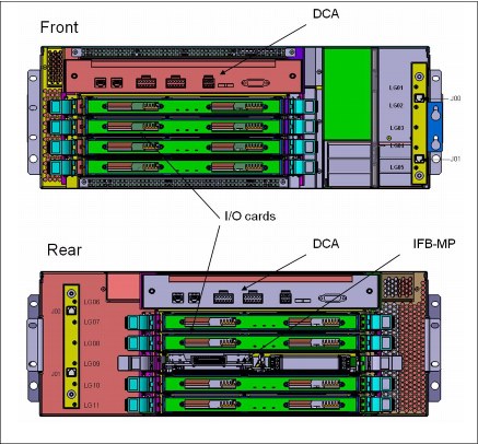
Figure 4-1 I/O drawer
The I/O structure in a z13 CPC is illustrated in Figure 4-2 on page 141. An IFB cable connects the HCA fanout card in the CPC drawer to an IFB-MP card in the I/O drawer. The passive connection between two IFB-MP cards allows redundant I/O interconnect (RII). RII provides connectivity between an HCA fanout card, and I/O cards in a concurrent fanout card or IFB cable replacement. The IFB cable between an HCA fanout card and each IFB-MP card supports a 6 GBps link rate.
|
Carry-forward only: Only two I/O drawers are supported in z13 on a carry-forward basis only and can host FICON Express8 cards only.
|
The I/O drawer domains and their related I/O slots are shown in Figure 4-2. The IFB-MP cards are installed at slot 09 at the rear side of the I/O drawer. The I/O features are installed from the front and rear side of the I/O drawer. Two I/O domains (A and B) are supported. Each I/O domain has up to four I/O features for FICON Express8 only (carry-forward). The I/O cards are connected to the IFB-MP card through the backplane board.
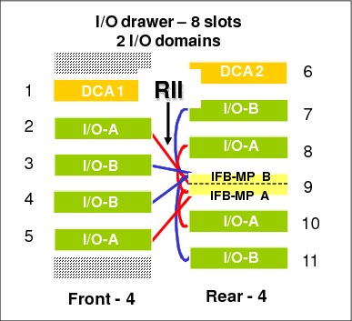
Figure 4-2 I/O domains of an I/O drawer
Each I/O domain supports four I/O card slots. Balancing I/O cards across both I/O domains is automatically done when the order is placed. Table 4-1 lists the I/O domains and their related I/O slots.
Table 4-1 I/O domains of I/O drawer
|
Domain
|
I/O slot in domain
|
|
A
|
02, 05, 08, and 10
|
|
B
|
03, 04, 07, and 11
|
4.4 PCIe I/O drawer
The PCIe I/O drawers are attached to the CPC drawer through a PCIe bus and use PCIe as the infrastructure bus within the drawer. The PCIe I/O bus infrastructure data rate is up to 16 GBps. PCIe switch application-specific integrated circuits (ASICs) are used to fan out the host bus from the processor drawers to the individual I/O features. Up to 64 channels (32 PCIe I/O features) are supported versus the 32 channels (eight I/O features) that are offered with the I/O drawer. The PCIe I/O drawer is a two-sided drawer (I/O cards on both sides) that is 7U high. The drawer contains 32 I/O slots for feature cards, four switch cards (two in front, two in the back), two DCAs to provide redundant power, and two air-moving devices (AMDs) for redundant cooling.
The locations of the DCAs, AMDs, PCIe switch cards, and I/O feature cards in the PCIe I/O drawer are shown in Figure 4-3.

Figure 4-3 PCIe I/O drawer
The I/O structure in a z13 CPC is shown in Figure 4-4. The PCIe switch card provides the fanout from the high-speed x16 PCIe host bus to eight individual card slots. The PCIe switch card is connected to the drawers through a single x16 PCIe Gen 3 bus from a PCIe fanout card.
A switch card in the front is connected to a switch card in the rear through the PCIe I/O drawer board. This configuration provides a failover capability during a PCIe fanout card failure or CPC drawer upgrade. In the PCIe I/O drawer, the eight I/O feature cards that directly attach to the switch card constitute an I/O domain. The PCIe I/O drawer supports concurrent add and replace I/O features to enable you to increase I/O capability as needed without having to plan ahead.
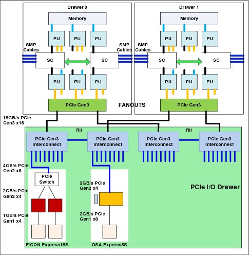
Figure 4-4 z13 connectivity to PCIe I/O drawers
The PCIe I/O Drawer supports up to 32 I/O features. They are organized into four hardware I/O domains per drawer. Each I/O domain supports up to eight features and is driven through a PCIe switch card. Two PCIe switch cards always provide a backup path for each other through the passive connection in the PCIe I/O drawer backplane. If there is a PCIe fanout card or cable failure, all 16 I/O cards in the two domains can be driven through a single PCIe switch card.
To support RII between front to back domain pairs 0 - 1 and 2 - 3, the two interconnects to each pair must be from two different PCIe fanout nodes within the processor drawers. All four domains in one of these PCIe I/O drawers can be activated with four fanouts. The flexible service processors (FSPs) are used for system control.
The PCIe I/O drawer domains and their related I/O slots are shown in Figure 4-5.

Figure 4-5 PCIe I/O drawer - 32 PCIe slots, four I/O domains
Each I/O domain supports up to eight features (FICON, OSA, and Crypto), and up to two native PCIe features (Flash Express, zEDC Express, and 10GbE RoCE Express). All I/O cards connect to the PCIe switch card through the backplane board.
Table 4-2 lists the I/O domains and slots.
Table 4-2 I/O domains of PCIe I/O drawer
|
Domain
|
I/O slot in domain
|
|
0
|
01, 02, 03, 04, 06, 07, 08, and 09
|
|
1
|
30, 31, 32, 33, 35, 36, 37, and 38
|
|
2
|
11, 12, 13, 14, 16, 17, 18, and 19
|
|
3
|
20, 21, 22, 23, 25, 26, 27, and 28
|
4.5 PCIe I/O drawer and I/O drawer offerings
A maximum of five PCIe I/O drawers can be installed that support up to 160 PCIe I/O features. Only PCIe I/O features can be ordered for a new system, and the configurator determines how many PCIe I/O drawers are required. If there is an upgrade to z13, the correct mix of I/O drawers and PCIe I/O drawers is determined based on the type and number of I/O features (new and carry-forward) that are required. I/O drawers cannot be ordered.
|
Consideration: On a new build z13, only PCIe I/O drawers are supported. A mixture of I/O drawers, and PCIe I/O drawers are available only on upgrades to a z13.
|
The PCIe I/O drawers support the following PCIe features:
•FICON Express16S
•FICON Express8S
•OSA-Express5S
•OSA-Express4S
•10GbE RoCE Express
•Crypto Express5S
•Flash Express
•zEDC Express
A maximum of two I/O drawers can be carried forward for FICON Express8 cards (also carry-forward). As such, a maximum of 16 FICON Express8 cards (a total of 64 FICON Express8 ports) can be carried forward.
|
Consideration: FICON Express8 cards are supported as carry-forward only for z13. They are installed in an I/O drawer. The installation of an I/O drawer limits the LPAR storage size to 1 TB (independent from the IOCP definition). Moreover, each I/O drawer affects the configuration as follows:
•The total fanout slots for PSIFB are reduced by two (independent of the carry-forward of one or two I/O drawers; two HCA2-C fanout cards are required in both cases).
•The maximum number of PCIe I/O features is reduced by 32.
•The maximum number of FICON channels is reduced by 32.
|
4.6 Fanouts
The z13 server uses fanout cards to connect the I/O subsystem to the CPC drawer. The cards also provide the ICA SR and InfiniBand coupling links for Parallel Sysplex. All fanout cards support concurrent add, delete, and move.
The internal z13 I/O infrastructure consists of PCIe fanout cards and InfiniBand fanout cards:
•The PCIe Generation3 fanout card is a one port card and connects to a PCIe I/O drawer supporting an eight-slot I/O domain. This card is always installed in pairs to support I/O domain redundant connectivity.
•The InfiniBand HCA2-C fanout card is available for carry-forward of FICON Express8 features that are installed in I/O drawers.
The PCIe and InfiniBand fanouts are installed in the front of each CPC drawer. Each CPC drawer has 10 PCIe Gen3 fanout slots and four InfiniBand fanout slots. The PCIe fanout slots are named LG02 - LG06 and LG11 - LG15, left to right. The InfiniBand fanout slots are in the middle of the CPC drawer and are named LG07 - LG10, left to right. Slots LG01 and LG16 are not used for I/O infrastructure.
Five types of fanout cards are supported by z13. Each slot can hold one of the following five fanouts:
•PCIe Gen3 fanout card: This copper fanout provides connectivity to the PCIe switch card in the PCIe I/O drawer.
•Host Channel Adapter (HCA2-C): This copper fanout provides connectivity to the IFB-MP card in the I/O drawer.
•Integrated Coupling Adapter (ICA SR): This adapter provides coupling connectivity between two z13 servers.
•Host Channel Adapter (HCA3-O (12xIFB)): This optical fanout provides 12x InfiniBand coupling link connectivity up to 150-meter (492 ft) distance to a z13, zEC12, zBC12, z196, and z114.
•Host Channel Adapter (HCA3-O LR (1xIFB)): This optical long range fanout provides 1x InfiniBand coupling link connectivity up to a 10 km (6.2 miles) unrepeated (or 100 km (62 miles) when extended by using z Systems qualified dense wavelength division multiplexing (DWDM) equipment) distance to z13, zEC12, zBC12, z196 and z114.
The PCIe Gen3 fanout card comes with one port, the HCA3-O LR (1xIFB) fanout comes with four ports, and other fanouts come with two ports.
Figure 4-6 illustrates the following PCIe and IFB connections from the CPC drawer:
•A PCIe I/O drawer (PCIe Gen3)
•Another CPC through InfiniBand (either 12x or 1x HCA3-O)
•Another z13 connected through a dedicated PCIe Integrated Coupling Adapter (ICA SR)
|
Important: Figure 4-6 shows an I/O connection scheme that is not tied to a particular CPC drawer. In a real configuration I/O connectivity is mixed across multiple CPC drawers, if available, for I/O connection redundancy.
|
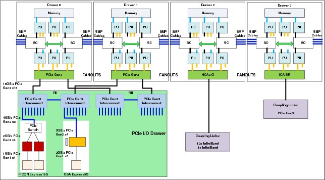
Figure 4-6 PCIe I/O infrastructure and PCIe and InfiniBand coupling links
4.6.1 PCIe Generation 3 fanout (FC 0173)
The PCIe Generation 3 fanout card provides connectivity to an PCIe I/O drawer by using a copper cable. There is one port on the fanout card that is dedicated for PCIe I/O. The bandwidth of this PCIe fanout card supports a link rate of 16 GBps.
A 16x PCIe copper cable of 1.5 meters (4.92 ft) to 4.0 meters (13.1 ft) is used for connection to the PCIe switch card in the PCIe I/O drawer. PCIe fanout cards are always plugged in pairs and provide redundancy for I/O domains within the PCIe I/O drawer.
The pairs of PCIe fanout cards of a z13 Model N30 are split across the two logical nodes within a CPC drawer (LG02 - LG06 and LG11 - LG15). All remaining models split the PCIe fanout pairs across different processor drawers for redundancy purposes.
|
PCIe fanout: The PCIe fanout is used exclusively for I/O and cannot be shared for any other purpose.
|
4.6.2 HCA2-C fanout (FC 0162)
The HCA2-C fanout is used to connect to an I/O drawer by using a copper cable. The two ports on the fanout are dedicated to I/O. The bandwidth of each port on the HCA2-C fanout supports a link rate of up to 6 GBps.
A 12x InfiniBand copper cable of 1.5 meters (4.92 ft) to 3.5 meters (11.4 ft) is used for connection to the IFB-MP card in the I/O drawer. An HCA2-C fanout is supported only if carried forward with an MES from z196, or zBC12 to z13. For a new z13 installation, it is not possible to have HCA2-C.‘
|
HCA2-C fanout: The HCA2-C fanout is used exclusively for a connection to the I/O drawer. It cannot be shared for any other purpose.
|
4.6.3 Integrated Coupling Adapter (FC 0172)
The IBM Integrated Coupling Adapter (ICA SR), introduced on the z13 platform, is a two-port fanout that is used for short distance coupling connectivity and uses a new coupling channel type, the CS5. The ICA SR uses PCIe Gen3 technology, with x16 lanes that are bifurcated into x8 lanes for coupling. No performance degradation is expected compared to the Coupling over InfiniBand 12x IFB3 protocol. The ICA SR is designed to drive distances up to 150 m and supports a link data rate of 8 GBps. It is also designed to support up to four CHPIDs per port and seven subchannels (devices) per CHPID. The coupling links can be defined as shared between images within a CSS. They also can be spanned across multiple CSSs in a CPC. Unlike the HCA3-O 12x InfiniBand links, the ICA SR cannot define more than four CHPIDS per port.
The ICA SR fanout is housed in the PCIe I/O fanout slot on the z13 CPC drawer, which supports 10 PCIe I/O slots. Up to 10 ICA SR fanouts and up to 20 ICA SR ports are supported on a z13 CPC drawer, enabling greater connectivity for short distance coupling on a single processor node compared to previous generations. The maximum number of ICA SR fanout features is limited to 16 per system.
The ICA SR can be used only for coupling connectivity between z13 servers. It does not support connectivity to zEC12, zBC12, z196, or z114 servers, and it cannot be connected to HCA3-O or HCA3-O LR coupling fanouts.
The ICA SR fanout requires new cabling. For distances up to 100 m, clients can choose the OM3 fiber optic cable. For distances up to 150 m, clients must choose the OM4 fiber optic cable. For more information, see Planning for Fiber Optic Links, GA23-1407, and IBM z13 Installation Manual for Physical Planning, GC28-6938, which can be found in the Library section of Resource Link at the following website:
4.6.4 HCA3-O (12x IFB) fanout (FC 0171)
The HCA3-O fanout for 12x InfiniBand provides an optical interface that is used for coupling links. The two ports on the fanout are dedicated to coupling links that connect to z13, zEC12, zBC12, z196, and z114 CPCs. Up to 16 HCA3-O (12x IFB) fanouts are supported, and provide up to 32 ports for coupling links.
The fiber optic cables are industry standard OM3 (2000 MHz-km) 50-µm multimode optical cables with MPO connectors. The maximum cable length is 150 meters (492 ft). There are
12 pairs of fibers: 12 fibers for transmitting, and 12 fibers for receiving. The HCA3-O (12xIFB) fanout supports a link data rate of 6 GBps.
12 pairs of fibers: 12 fibers for transmitting, and 12 fibers for receiving. The HCA3-O (12xIFB) fanout supports a link data rate of 6 GBps.
|
Important: The HCA3-O fanout has two ports (1 and 2). Each port has one connector for transmitting (TX) and one connector for receiving (RX). Ensure that you use the correct cables. An example is shown in Figure 4-7.
|

Figure 4-7 OM3 50/125 µm multimode fiber cable with MPO connectors
A fanout has two ports for optical link connections, and supports up to 16 CHPIDs across both ports. These CHPIDs are defined as channel type CIB in the IOCDS. The coupling links can be defined as shared between images within a CSS. They also can be spanned across multiple CSSs in a CPC.
Each HCA3-O (12x IFB) fanout that is used for coupling links has an assigned Adapter ID (AID) number. This number must be used for definitions in IOCDS to create a relationship between the physical fanout location and the CHPID number. For more information about AID numbering, see “Adapter ID number assignment” on page 150.
For more information about how the AID is used and referenced in the HCD, see Implementing and Managing InfiniBand Coupling Links on System z, SG24-7539.
When STP is enabled, IFB coupling links can be defined as timing-only links to other z13, zEC12, zBC12, z196, and z114 CPCs.
12x IFB and 12x IFB3 protocols
These protocols are supported by the HCA3-O for 12x IFB feature:
•12x IFB3 protocol: When HCA3-O (12xIFB) fanouts are communicating with HCA3-O (12x IFB) fanouts and are defined with four or fewer CHPIDs per port, the 12x IFB3 protocol is used.
•12x IFB protocol: If more than four CHPIDs are defined per HCA3-O (12xIFB) port, or HCA3-O (12x IFB) features are communicating with HCA2-O (12x IFB) features on zEnterprise or System z10 CPCs, links run with the 12x IFB protocol.
The HCA3-O feature that supports 12x InfiniBand coupling links is designed to deliver improved service times. When no more than four CHPIDs are defined per HCA3-O (12xIFB) port, the 12x IFB3 protocol is used. When you use the 12x IFB3 protocol, synchronous service times are up to 40% faster than when you use the 12x IFB protocol. Unlike the HCA3-O 12x InfiniBand links, the ICA SR cannot define more than four CHPIDS per port.
4.6.5 HCA3-O LR (1x IFB) fanout (FC 0170)
The HCA3-O LR fanout for 1x InfiniBand provides an optical interface that is used for coupling links. The four ports on the fanout are dedicated to coupling links to connect to z13, zEC12, zBC12, z196, and z114 servers. Up to 16 HCA3-O LR (1xIFB) fanouts are supported by z13, and provide up to 64 ports for coupling links.
The HCA-O LR fanout supports InfiniBand 1x optical links that offer long-distance coupling links. The cable has one lane that contains two fibers. One fiber is used for transmitting, and the other fiber is used for receiving data.
Each connection supports a link rate of up to 5 Gbps if connected to a z13, zEC12, zBC12, z196, or z114. It supports a link rate of 2.5 Gbps when connected to a z Systems qualified DWDM. The link rate is auto-negotiated to the highest common rate.
The fiber optic cables are 9-µm SM optical cables that terminate with an LC Duplex connector. The maximum unrepeated distance is 10 km (6.2 miles), and up to 100 km (62 miles) with z Systems qualified DWDM. RPQ 8P2263 or RPQ 8P2340 is required for 20 km
(12.4 miles) support. Going beyond 100 km (62 miles) requires RPQ 8P2263 or RPQ 8P2340.
(12.4 miles) support. Going beyond 100 km (62 miles) requires RPQ 8P2263 or RPQ 8P2340.
A fanout has four ports for optical link connections, and supports up to 16 CHPIDs across all four ports. These CHPIDs are defined as channel type CIB in the IOCDS. The coupling links can be defined as shared between images within a channel subsystem, and also can be spanned across multiple CSSs in a server.
Each HCA3-O LR (1xIFB) fanout can be used for link definitions to another server, or a link from one port to a port in another fanout on the same server.
The source and target operating system image, CF image, and the CHPIDs that are used on both ports in both servers are defined in IOCDS.
Each HCA3-O LR (1xIFB) fanout that is used for coupling links has an assigned AID number. This number must be used for definitions in IOCDS to create a relationship between the physical fanout location and the CHPID number. For more information about AID numbering, see “Adapter ID number assignment” on page 150.
When STP is enabled, IFB LR coupling links can be defined as timing-only links to other z13, zEC12, zBC12, z196, and z114 CPCs.
4.6.6 Fanout considerations
Fanout slots in each CPC drawer can be used to plug different fanouts. One drawer can hold up to 10 PCIe fanouts and four InfiniBand fanout cards.
For migration purposes, the number of available HCA3 or HCA3 LR cards in the z13 can be important (for coupling connectivity to zEC12, zBC12, z196, and z114). The carry-forward of FICON Express8 features reduces the number of available InfiniBand fanout slots by two. This limitation can be important for coupling connectivity planning, especially for a z13 Model N30, as shown in table Table 4-3. There are only two fanout adapter slots for HCA3 or HCA3 LR features that are available for a one CPC drawer model after a FICON Express8 feature is carried forward. Table 4-3 shows the z13 models N30 and N63 where the limitation of HCA3 and HCA3 LR cards that are caused by carry-forward of FICON Express8 features might require attention during migration. For a three or four CPC drawer, the IFB fanout capability is relieved because the total number of IFB fanout slots increases with each additional CPC drawer.
For migration considerations, see 4.9.2, “Migration considerations” on page 173.
Table 4-3 CPC drawer InfiniBand fanout availability limitation with carry-forward FICON Express8 features
|
CPC Model
|
Carry forward FICON Express8 features
|
Resulting number of I/O drawers
|
Max. number of HCA3 or HCA3 LR fanout cards
|
Max. number of PCIe I/O drawers
|
Max. number of PCIe I/O features
|
|
N30
|
0
|
0
|
4
|
31
|
80
|
|
1 - 8
|
1
|
2
|
|||
|
9 - 16
|
2
|
2
|
|||
|
N63
|
0
|
0
|
8
|
5
|
160
|
|
1 - 8
|
1
|
6
|
|||
|
9 - 16
|
2
|
6
|
1 The third PCIe I/O drawer can be populated only with two I/O domains (16 I/O features).
Adapter ID number assignment
PCIe and IFB fanouts and ports are identified by an AID that is initially dependent on their physical locations, which is unlike channels that are installed in a PCIe I/O drawer or I/O drawer. Those channels are identified by a physical channel ID (PCHID) number that is related to their physical location. This AID must be used to assign a CHPID to the fanout in the IOCDS definition. The CHPID assignment is done by associating the CHPID to an AID port.
Table 4-4 illustrates the AID assignment for each fanout slot relative to the drawer location on a new build system.
Table 4-4 AID number assignment
|
Drawer
|
Location
|
Fanout slot
|
AIDs
|
|
First
|
A15A
|
LG02-LG06 (PCIe)
|
2E-32
|
|
LG07-LG10 (IFB)
|
0C-0F
|
||
|
LG11-LG15 (PCIe)
|
33-37
|
||
|
Second
|
A19A
|
LG02-LG06 (PCIe)
|
24-28
|
|
LG07-LG10 (IFB)
|
08-0B
|
||
|
LG11-LG15 (PCIe)
|
29-2D
|
||
|
Third
|
A23A
|
LG02-LG06 (PCIe)
|
1A-1E
|
|
LG07-LG10 (IFB)
|
04-07
|
||
|
LG11-LG15 (PCIe)
|
1F-23
|
||
|
Fourth
|
A27A
|
LG02-LG06 (PCIe)
|
10-14
|
|
LG07-LG10 (IFB)
|
00-03
|
||
|
LG11-LG15 (PCIe)
|
15-19
|
Fanout slots
The fanout slots are numbered LG02 - LG15 left to right, as shown in Table 4-4. All fanout locations and their AIDs for all four drawers are shown in Table 4-4 for reference only. Slots LG01 and LG16 never have a fanout installed because they are dedicated for FSPs.
|
Important: The AID numbers in Table 4-4 are valid only for a new build system or if new processor drawers are added. If a fanout is moved, the AID follows the fanout to its new physical location.
|
The AID that is assigned to a fanout is in the PCHID REPORT that is provided for each new server or for an MES upgrade on existing servers.
Example 4-1 shows part of a report, named PCHID REPORT, for a model NE1. In this example, one fanout is installed in the first drawer (location A15A slot LG02) and one fanout is installed in the second drawer (location A19A slot LG11). The assigned AID for the fanout in the first drawer is 2E. The AID that is assigned to the fanout in the second drawer is 29.
Example 4-1 AID assignment in PCHID REPORT
CHPIDSTART
12345678 PCHID REPORT Oct 31,2014
Machine: 2964-NE1 SNXXXXXXX
- - - - - - - - - - - - - - - - - - - - - - - - - - - - - - - - - - - - - - -
Source Cage Slot F/C PCHID/Ports or AID Comment
A15/LG02 A15A LG02 0172 AID=2E
A19/LG11 A19A LG11 0172 AID=29
Fanout features that are supported by the z13 server are shown in Table 4-5. The table provides the feature type, feature code, and information about the link that is supported by the fanout feature.
Table 4-5 Fanout summary
|
Fanout feature
|
Feature code
|
Use
|
Cable
type |
Connector type
|
Maximum distance
|
Link data rate
|
|
HCA2-C
|
0162
|
Connect to I/O drawer
|
Copper
|
N/A
|
3.5 m
(11.48 ft) |
6 GBps
|
|
PCIe fanout
|
0173
|
Connect to PCIe I/O drawer
|
Copper
|
N/A
|
4 m (13.1 ft)
|
16 GBps
|
|
HCA3-O (12xIFB)
|
0171
|
Coupling link
|
50-µm MM OM3 (2000 MHz-km)
|
MPO
|
150 m (492 ft)
|
6 GBps1
|
|
HCA3-O LR (1xIFB)
|
0170
|
Coupling link
|
9-µm SM
|
LC Duplex
|
10 km2
(6.2 miles) |
5.0 Gbps
2.5 Gbps3
|
|
ICA SR
|
0172
|
Coupling link
|
OM4
|
MTP
|
150 m (492 ft)
|
8 Gbps
|
|
OM3
|
MTP
|
100 m (328 ft)
|
8 Gbps
|
1 When using the 12x IFB3 protocol, synchronous service times are 40% faster than when you use the 12x IFB protocol.
2 Up to 100 km (62 miles) with repeaters (z Systems qualified DWDM).
3 Auto-negotiated, depending on the DWDM equipment.
4.7 I/O features (cards)
I/O features (cards) have ports4 to connect the z13 to external devices, networks, or other servers. I/O features are plugged into the PCIe I/O drawer, based on the configuration rules for the server. Different types of I/O cards are available, one for each channel or link type. I/O cards can be installed or replaced concurrently.
In addition to PCIe I/O features, FICON Express8 features can be installed in I/O drawers. The z13 supports a maximum of two I/O drawers as carry-forward during an MES. This represents a maximum of 16 FICON Express8 features (a total of 64 FICON Express8 ports) that can be carried forward.
|
Consideration: The installation of an I/O drawer limits the LPAR storage to 1 TB (independent from the IOCP definition). Moreover, each I/O drawer affects the configuration as follows:
•The total fanout slots for PSIFB are reduced by two (independent of the carry-forward of one or two I/O drawers; two HCA2-C fanout cards are required in both cases).
•The maximum number of PCIe I/O features is reduced by 32.
•The maximum number of FICON channels is reduced by 32.
|
4.7.1 I/O feature card ordering information
Table 4-6 lists the I/O features that are supported by z13 and the ordering information for them.
Table 4-6 I/O features and ordering information
|
Channel feature
|
Feature code
|
New build
|
Carry-forward
|
|
FICON Express16S 10KM LX
|
0418
|
Y
|
N/A
|
|
FICON Express16S SX
|
0419
|
Y
|
N/A
|
|
FICON Express8S 10KM LX
|
0409
|
Y
|
Y
|
|
FICON Express8S SX
|
0410
|
Y
|
Y
|
|
FICON Express8 10KM LX
|
3325
|
N
|
Y
|
|
FICON Express8 SX
|
3326
|
N
|
Y
|
|
OSA-Express5S 10 GbE LR
|
0415
|
Y
|
Y
|
|
OSA-Express5S 10 GbE SR
|
0416
|
Y
|
Y
|
|
OSA-Express5S GbE LX
|
0413
|
Y
|
Y
|
|
OSA-Express5S GbE SX
|
0414
|
Y
|
Y
|
|
OSA-Express5S 1000BASE-T Ethernet
|
0417
|
Y
|
Y
|
|
OSA-Express4S 10 GbE LR
|
0406
|
N
|
Y
|
|
OSA-Express4S 10 GbE SR
|
0407
|
N
|
Y
|
|
OSA-Express4S GbE LX
|
0404
|
N
|
Y
|
|
OSA-Express4S GbE SX
|
0405
|
N
|
Y
|
|
OSA-Express4S 1000BASE-T Ethernet
|
0408
|
N
|
Y
|
|
Integrated Coupling Adapter (ICA SR)
|
0172
|
Y
|
N/A
|
|
HCA3-O (12xIFB)
|
0171
|
Y
|
Y
|
|
HCA3-O LR (1xIFB)
|
0170
|
Y
|
Y
|
|
Crypto Express5S
|
0890
|
Y
|
Y
|
|
Flash Express
|
0403
|
Y
|
N/A
|
|
Flash Express
|
0402
|
N
|
Y
|
|
10GbE RoCE Express
|
0411
|
Y
|
Y
|
|
zEDC Express
|
0420
|
Y
|
Y
|
|
Important: z13 does not support the ISC-3, HCA2-O (12x), and HCA2-O LR (1x) features and cannot participate in a Mixed CTN.
|
4.7.2 Physical channel (PCHID) report
A PCHID reflects the physical location of a channel-type interface.
A PCHID number is based on these factors:
•The I/O drawer, and PCIe I/O drawer location
•The channel feature slot number
•The port number of the channel feature
A CHPID does not directly correspond to a hardware channel port, but it is assigned to a PCHID in the hardware configuration definition (HCD) or input/output configuration program (IOCP).
A PCHID REPORT is created for each new build server and for upgrades on existing servers. The report lists all I/O features that are installed, the physical slot location, and the assigned PCHID. Example 4-2 shows a portion of a sample PCHID REPORT. For more information about the AID numbering rules for InfiniBand coupling links, see Table 4-4 on page 151.
Example 4-2 PCHID REPORT
CHPIDSTART
12345678 PCHID REPORT Oct 28,2014
Machine: 2964-NE1 SNXXXXXXX
- - - - - - - - - - - - - - - - - - - - - - - - - - - - - - - - - - - - - - -
Source Cage Slot F/C PCHID/Ports or AID Comment
A27/LG07 A27A LG07 0170 AID=00
A15/LG04 A15A LG04 0172 AID=30
A19/LG15/J01 Z22B 03 0414 108/D1D2
A19/LG15/J01 Z22B 04 0418 10C/D1 10D/D2
A19/LG03/J01 Z08B 20 0411 240/D1D2 RG2
A27/LG14/J01 Z01B 03 0420 288 RG1
A23/LG14/J01 Z01B 19 0411 2BC/D1D2 RG1
A15/LG05/J01 A32B 38 0420 37C RG2
Legend:
Source Book Slot/Fanout Slot/Jack
A15A Processor Drawer 1 in A frame
A19A Processor Drawer 2 in A frame
A23A Processor Drawer 3 in A frame
A27A Processor Drawer 4 in A frame
Z22B PCIe Drawer 1 in Z frame
Z15B PCIe Drawer 2 in Z frame
Z08B PCIe Drawer 3 in Z frame
Z01B PCIe Drawer 4 in Z frame
A32B PCIe Drawer 5 in A frame
RG1 Resource Group One
RG2 Resource Group Two
0170 HCA3 0 LR PSIFB 1x 4 Links
0172 Integrated Coupling Adapter (ICA SR) 2 Links
0411 10GbE RoCE Express
0414 OSA Express5S GbE SX 2 Ports
0418 16 Gbps FICON/FCP LX 2 Ports
0420 zEDC Express
The following list explains the content of the sample PCHID REPORT:
•Feature code 0170 (HCA3-O LR (1xIFB)) is installed in CPC drawer 4 (location A27A, slot LG07), and has AID 00 assigned.
•Feature code 0172 (Integrated Coupling Adapter (ICA SR) is installed in CPC drawer 1 (location A15A, slot LG04), and has AID 30 assigned.
•Feature code 0414 (OSA-Express5S GbE short wavelength (SX)) is installed in PCIe I/O drawer 2 (location Z22B, slot 03), and has PCHID 108 assigned. PCHID 108 is shared by ports D0 and D1.
•Feature code 0418 (FICON Express16S long wavelength (LX) 10 km (6.2 miles)) is installed in PCIe I/O drawer 2 (location Z22B, slot 04), and has PCHIDs 10C and 10D assigned.
•Feature code 0411 (10GbE RoCE Express) is installed in PCIe I/O drawer 3 (location Z08B, slot 20), and has PCHID 240 assigned. PCHID 240 is shared by ports D0 and D1.
A resource group (RG) parameter is shown in the PCHID REPORT for native PCIe features. There is a balanced plugging of native PCIe features between two resource groups (RG1 and RG2).
For details about resource groups, see Appendix G, “Native Peripheral Component Interconnect Express (PCIe)” on page 527.
The preassigned PCHID number of each I/O port relates directly to its physical location (jack location in a specific slot).
4.8 Connectivity
I/O channels are part of the channel subsystem (CSS). They provide connectivity for data exchange between servers, or between servers and external control units (CUs) and devices, or between networks.
Communication between servers is implemented by using Integrated Coupling Adapter (ICA SR), 10GbE RoCE Express, coupling over InfiniBand, or channel-to-channel (CTC) connections.
Communication to LANs is provided by the OSA-Express5S, and OSA-Express4S features.
Connectivity to I/O subsystems to exchange data is provided by FICON channels.
4.8.1 I/O feature support and configuration rules
Table 4-7 lists the I/O features that are supported. The table shows the number of ports per card, port increments, the maximum number of feature cards, and the maximum number of channels for each feature type. Also, the CHPID definitions that are used in the IOCDS are listed.
Table 4-7 z13 supported I/O features
|
I/O feature
|
Number of
|
Maximum number of
|
PCHID
|
CHPID definition
|
||
|
Ports per card
|
Port increments
|
Ports
|
I/O slots
|
|||
|
FICON Express16S LX/SX
|
2
|
2
|
320
|
160
|
Yes
|
FC, FCP
|
|
FICON Express8S LX/SX
|
2
|
2
|
320
|
160
|
Yes
|
FC, FCP
|
|
FICON Express8 LX/SX
|
4
|
4
|
64
|
16
|
Yes
|
FC, FCP
|
|
OSA-Express5S 10 GbE LR/SR
|
1
|
1
|
48
|
48
|
Yes
|
OSD, OSX
|
|
OSA-Express5S GbE LX/SX
|
2
|
2
|
96
|
48
|
Yes
|
OSD
|
|
OSA-Express5S 1000BASE-T
|
2
|
2
|
96
|
48
|
Yes
|
OSC, OSD, OSE, OSM, OSN
|
|
OSA- Express4S 10 GbE LR/SR
|
1
|
1
|
48
|
48
|
Yes
|
OSD, OSX
|
|
OSA-Express4S GbE LX/SX
|
2
|
2
|
96
|
48
|
Yes
|
OSD
|
|
OSA-Express4S 1000BASE-T
|
2
|
2
|
96
|
48
|
Yes
|
OSC, OSD, OSE, OSM, OSN
|
|
10GbE RoCE Express
|
2
|
2
|
32
|
16
|
Yes
|
N/A1
|
|
Integrated Coupling Adapter (ICA SR)
|
2
|
2
|
32
|
16
|
N/A2
|
CS5
|
|
HCA3-O for 12x IFB and 12x IFB3
|
2
|
2
|
32
|
16
|
N/Ab
|
CIB
|
|
HCA3-O LR for 1x IFB
|
4
|
4
|
64
|
16
|
N/Ab
|
CIB
|
1 Defined by PFID (PCIe Function ID).
2 identified by AID (Adapter identification) instead of a PCHID.
At least one I/O feature (FICON) or one coupling link feature (ICA SR or HCA3-O) must be present in the minimum configuration. A maximum of 256 channels is configurable per channel subsystem and per operating system image.
The following features can be shared and spanned:
•FICON channels that are defined as FC or FCP
•OSA-Express5S features that are defined as OSC, OSD, OSE, OSM, OSN, or OSX
•OSA-Express4S features that are defined as OSC, OSD, OSE, OSM, OSN, or OSX
•Coupling links that are defined as CS5, CIB, or ICP
•HiperSockets that are defined as IQD
The following features are exclusively plugged into a PCIe I/O drawer and do not require the definition of a CHPID and CHPID type:
•Each Crypto Express feature occupies one I/O slot, but does not have a CHPID type. However, logical partitions (LPARs) in all CSSs have access to the features. Each Crypto Express adapter can be defined to up to 85 LPARs.
•Each Flash Express feature occupies two I/O slots but does not have a CHPID type. However, LPARs in all CSSs have access to the features. The Flash Express feature can be defined to up to 85 LPARs.
•Each RoCE feature occupies one I/O slot but does not have a CHPID type. However, LPARs in all CSSs have access to the feature. The RoCE feature can be defined to up to 31 LPARs.
•Each zEDC feature occupies one I/O slot but does not have a CHPID type. However, LPARs in all CSSs have access to the feature. The zEDC feature can be defined to up to 15 LPARs.
I/O feature cables and connectors
The IBM Facilities Cabling Services fiber transport system offers a total cable solution service to help with cable ordering requirements. These services can include the requirements for all of the protocols and media types that are supported (for example, FICON, Coupling Links, and OSA). The services can help whether the focus is the data center, a SAN, a LAN, or the end-to-end enterprise.
|
Cables: All fiber optic cables, cable planning, labeling, and installation are client responsibilities for new z13 installations and upgrades. Fiber optic conversion kits and mode conditioning patch cables are not orderable as features on z13 servers. All other cables must be sourced separately.
|
The Enterprise Fiber Cabling Services use a proven modular cabling system, the fiber transport system (FTS), which includes trunk cables, zone cabinets, and panels for servers, directors, and storage devices. FTS supports Fiber Quick Connect (FQC), a fiber harness that is integrated in the frame of a z13 for quick connection. The FQC is offered as a feature on z13 servers for connection to FICON LX channels.
Whether you choose a packaged service or a custom service, high-quality components are used to facilitate moves, additions, and changes in the enterprise to prevent having to extend the maintenance window.
Table 4-8 lists the required connector and cable type for each I/O feature on the z13.
Table 4-8 I/O feature connector and cable types
|
Feature code
|
Feature name
|
Connector type
|
Cable type
|
|
0418
|
FICON Express16S LX 10 km
|
LC Duplex
|
9 µm SM1
|
|
0419
|
FICON Express16S SX
|
LC Duplex
|
50, 62.5 µm MM2
|
|
0409
|
FICON Express8S LX 10 km
|
LC Duplex
|
9 µm SM
|
|
0410
|
FICON Express8S SX
|
LC Duplex
|
50, 62.5 µm MM
|
|
3325
|
FICON Express8 LX 10 km
|
LC Duplex
|
9 µm SM
|
|
3326
|
FICON Express8 SX
|
LC Duplex
|
50, 62.5 µm MM
|
|
0415
|
OSA-Express5S 10 GbE LR
|
LC Duplex
|
9 µm SM
|
|
0416
|
OSA-Express5S 10 GbE SR
|
LC Duplex
|
50, 62.5 µm MM
|
|
0413
|
OSA-Express5S GbE LX
|
LC Duplex
|
9 µm SM
|
|
0414
|
OSA-Express5S GbE SX
|
LC Duplex
|
50, 62.5 µm MM
|
|
0417
|
OSA-Express5S 1000BASE-T
|
RJ-45
|
Category 5 UTP3
|
|
0404
|
OSA-Express4S GbE LX
|
LC Duplex
|
9 µm SM
|
|
0405
|
OSA-Express4S GbE SX
|
LC Duplex
|
50, 62.5 µm MM
|
|
0406
|
OSA-Express4S 10 GbE LR
|
LC Duplex
|
9 µm SM
|
|
0407
|
OSA-Express4S 10 GbE SR
|
LC Duplex
|
50, 62.5 µm MM
|
|
0408
|
OSA-Express4S 1000BASE-T
|
RJ-45
|
Category 5 UTP
|
|
0411
|
10GbE RoCE Express
|
LC Duplex
|
50, 62.5 µm MM
|
|
0172
|
Integrated Coupling Adapter (ICA SR)
|
MPO
|
50 µm MM OM4
(4.7 GHz-km)4 |
|
0171
|
HCA3-O (12xIFB)
|
MPO
|
50 µm MM OM3
(2 GHz-km) |
|
0170
|
HCA3-O LR (1xIFB)
|
LC Duplex
|
9 µm SM
|
1 SM is single-mode fiber.
2 MM is multimode fiber.
3 UTP is unshielded twisted pair. Consider using category 6 UTP for 1000 Mbps connections.
4 Or 50 µm MM OM3 (2 GHz-km), but OM4 is highly recommended.
4.8.2 FICON channels
The FICON Express16S, FICON Express8S, and FICON Express8 features conform to the following architectures:
•Fibre Connection (FICON)
•High Performance FICON on z Systems (zHPF)
•Fibre Channel Protocol (FCP)
They provide connectivity between any combination of servers, directors, switches, and devices (control units, disks, tapes, and printers) in a SAN.
Each FICON Express16S or FICON Express8S feature occupies one I/O slot in the PCIe I/O drawer. Each feature has two ports, each supporting an LC Duplex connector, with one PCHID and one CHPID associated with each port.
Each FICON Express8 feature occupies one I/O slot in the I/O drawer. Each feature has four ports, each supporting an LC Duplex connector, with one PCHID and one CHPID that is associated with each port.
All FICON Express16S, FICON Express8S, and FICON Express8 features use SFP optics that allow for concurrent repair or replacement for each SFP. The data flow on the unaffected channels on the same feature can continue. A problem with one FICON port no longer requires replacement of a complete feature.
All FICON Express16S, FICON Express8S, and FICON Express8 features also support cascading, which is the connection of two FICON Directors in succession. This configuration minimizes the number of cross-site connections and helps reduce implementation costs for disaster recovery applications, IBM Geographically Dispersed Parallel Sysplex™ (GDPS®), and remote copy.
FICON Express8S, and FICON Express8 features support 24 K I/O devices (subchannels) for base and alias devices.
FICON Express16S feature support 32 K I/O devices (subchannels) per FICON channel for base and alias devices.
Each FICON Express16S, FICON Express8S, and FICON Express8 channel can be defined independently for connectivity to servers, switches, directors, disks, tapes, and printers:
•CHPID type FC: FICON, zHPF, and FCTC. All of these protocols are supported simultaneously.
•CHPID type FCP: Fibre Channel Protocol that supports attachment to SCSI devices directly or through Fibre Channel switches or directors.
FICON channels (CHPID type FC or FCP) can be shared among LPARs and can be defined as spanned. All ports on a FICON feature must be of the same type, either LX or SX. The features are connected to a FICON capable control unit, either point-to-point or switched point-to-point, through a Fibre Channel switch.
|
Statement of Direction1: The z13 is the last z Systems server to support FICON Express8 features for 2 Gbps connectivity.
|
1 All statements regarding IBM plans, directions, and intent are subject to change or withdrawal without notice. Any reliance on these statements of general direction is at the relying party’s sole risk and will not create liability or obligation for IBM.
FICON Express16S
The FICON Express16S feature is exclusively in the PCIe I/O drawer. Each of the two independent ports is capable of 4 Gbps, 8 Gbps, or 16 Gbps. The link speed depends on the capability of the attached switch or device. The link speed is auto-negotiated, point-to-point, and is transparent to users and applications.
The two types of FICON Express16S optical transceivers that are supported are the LX and the SX:
•FICON Express16S 10 km LX feature, FC 0418, with two ports per feature, supporting LC Duplex connectors
•FICON Express16S SX feature, FC 0419, with two ports per feature, supporting LC Duplex connectors
Each port of the FICON Express16S 10 km LX feature uses an optical transceiver, which supports an unrepeated distance of 10 km (6.2 miles) by using 9 µm single-mode fiber.
Each port of the FICON Express16S SX feature uses an optical transceiver, which supports to up to 125 m (410 feet) of distance depending on the fiber that is used.
|
Consideration: FICON Express16S features do not support auto-negotiation to a data link rate of 2 Gbps.
|
FICON Express8S
The FICON Express8S feature is exclusively in the PCIe I/O drawer. Each of the two independent ports is capable of 2 Gbps, 4 Gbps, or 8 Gbps. The link speed depends on the capability of the attached switch or device. The link speed is auto-negotiated, point-to-point, and is transparent to users and applications.
The two types of FICON Express8S optical transceivers that are supported are the LX and the SX:
•FICON Express8S 10 km LX feature, FC 0409, with two ports per feature, supporting LC Duplex connectors
•FICON Express8S SX feature, FC 0410, with two ports per feature, supporting LC Duplex connectors
Each port of the FICON Express8S 10 km LX feature uses an optical transceiver, which supports an unrepeated distance of 10 km (6.2 miles) by using 9 µm single-mode fiber.
Each port of the FICON Express8S SX feature uses an optical transceiver, which supports up to 150 m (492 feet) of distance depending on the fiber used.
FICON Express8
The FICON Express8 feature for z13 is in the I/O drawer (carry-forward only). Each of the four independent ports is capable of 2 Gbps, 4 Gbps, or 8 Gbps. The link speed depends on the capability of the attached switch or device. The link speed is auto-negotiated, point-to-point, and is transparent to users and applications.
The two types of FICON Express8 optical transceivers that are supported are the LX and the SX:
•FICON Express8 10 km LX feature, FC 3325, with four ports per feature, supporting LC Duplex connectors
•FICON Express8 SX feature, FC 3326, with four ports per feature, supporting LC Duplex connectors
Each port of FICON Express8 10 km LX feature uses an optical transceiver, which supports an unrepeated distance of 10 km (6.2 miles) by using 9 µm single-mode fiber.
Each port of FICON Express8 SX feature uses an optical transceiver, which supports to up to 150 m (492 feet) of distance depending on the fiber used.
FICON feature summary
Table 4-9 shows the FICON card feature codes, cable type, maximum unrepeated distance, and the link data rate on a z13. All FICON features use LC Duplex connectors.
Table 4-9 z13 channel feature support
|
Channel feature
|
Feature codes
|
Bit rate
|
Cable type
|
Maximum unrepeated distance1
|
|
FICON Express16S 10KM LX
|
0418
|
4, 8, or 16 Gbps
|
SM 9 µm
|
10 km
|
|
FICON Express16S SX
|
0419
|
16 Gbps
|
MM 62.5 µm
MM 50 µm
|
15 m (200)
35 m (500)
100 m (2000)
125 m (4700)
|
|
8 Gbps
|
MM 62.5 µm
MM 50 µm
|
21 m (200)
50 m (500)
150 m (2000)
190 m (4700)
|
||
|
4 Gbps
|
MM 62.5 µm
MM 50 µm
|
70 m (200)
150 m (500)
380 m (2000)
400 m (4700)
|
||
|
FICON Express8S 10KM LX
|
0409
|
2, 4, or 8 Gbps
|
SM 9 µm
|
10 km
|
|
FICON Express8S SX
|
0410
|
8 Gbps
|
MM 62.5 µm
MM 50 µm
|
21 m (200)
50 m (500)
150 m (2000)
190 m (4700)
|
|
4 Gbps
|
MM 62.5 µm
MM 50 µm
|
70 m (200)
150 m (500)
380 m (2000)
400 m (4700)
|
||
|
2 Gbps
|
MM 62.5 µm
MM 50 µm
|
150 m (200)
300 m (500)
500 m (2000)
N/A (4700)
|
||
|
FICON Express8 10KM LX
|
3325
|
2, 4, or 8 Gbps
|
SM 9 µm
|
10 km
|
|
FICON Express8 SX
|
3326
|
8 Gbps
|
MM 62.5 µm
MM 50 µm
|
21 m (200)
50 m (500)
150 m (2000)
190 m (4700)
|
|
4 Gbps
|
MM 62.5 µm
MM 50 µm
|
70 m (200)
150 m (500)
380 m (2000)
400 m (4700)
|
||
|
2 Gbps
|
MM 62.5 µm
MM 50 µm
|
150 m (200)
300 m (500)
500 m (2000)
N/A (4700)
|
1 Minimum fiber bandwidths in MHz/km for multimode fiber optic links are included in parentheses where applicable.
4.8.3 OSA-Express5S
The OSA-Express5S feature is exclusively in the PCIe I/O drawer. The following OSA-Express5S features can be installed on z13 servers:
•OSA-Express5S 10 Gigabit Ethernet LR, FC 0415
•OSA-Express5S 10 Gigabit Ethernet SR, FC 0416
•OSA-Express5S Gigabit Ethernet LX, FC 0413
•OSA-Express5S Gigabit Ethernet SX, FC 0414
•OSA-Express5S 1000BASE-T Ethernet, FC 0417
Table 4-10 lists the OSA-Express5S features.
Table 4-10 OSA-Express5S features
|
I/O feature
|
Feature code
|
Number of ports per feature
|
Port increment
|
Maximum number of ports
|
Maximum number of features
|
CHPID type
|
|
OSA-Express5S 10 GbE LR
|
0415
|
1
|
1
|
48
|
48
|
OSD,
OSX
|
|
OSA-Express5S 10 GbE SR
|
0416
|
1
|
1
|
48
|
48
|
OSD,
OSX
|
|
OSA-Express5S GbE LX
|
0413
|
2
|
2
|
96
|
48
|
OSD
|
|
OSA-Express5S GbE SX
|
0414
|
2
|
2
|
96
|
48
|
OSD
|
|
OSA-Express5S 1000BASE-T
|
0417
|
2
|
2
|
96
|
48
|
OSC, OSD, OSE, OSM, OSN
|
OSA-Express5S 10 Gigabit Ethernet LR (FC 0415)
The OSA-Express5S 10 Gigabit Ethernet (GbE) Long Reach (LR) feature has one PCIe adapter and one port per feature. The port supports CHPID types OSD and OSX. When defined as CHPID type OSX, the 10 GbE port provides connectivity and access control to the intraensemble data network (IEDN) from z13 to zEnterprise BladeCenter Extension (zBX). The 10 GbE feature is designed to support attachment to a single-mode fiber 10 Gbps Ethernet LAN or Ethernet switch that is capable of 10 Gbps. The port can be defined as a spanned channel and can be shared among LPARs within and across logical channel subsystems.
The OSA-Express5S 10 GbE LR feature supports the use of an industry standard small form factor LC Duplex connector. Ensure that the attaching or downstream device has an LR transceiver. The transceivers at both ends must be the same (LR to LR, which might also be referred to as LW or LX).
A 9 µm single-mode fiber optic cable that terminates with an LC Duplex connector is required for connecting this feature to the selected device.
OSA-Express5S 10 Gigabit Ethernet SR (FC 0416)
The OSA-Express5S 10 Gigabit Ethernet (GbE) Short Reach (SR) feature has one PCIe adapter and one port per feature. The port supports CHPID types OSD and OSX. When defined as CHPID type OSX, the 10 GbE port provides connectivity and access control to the IEDN from z13 to zBX. The 10 GbE feature is designed to support attachment to a multimode fiber 10 Gbps Ethernet LAN or Ethernet switch that is capable of 10 Gbps. The port can be defined as a spanned channel and can be shared among LPARs within and across logical channel subsystems.
The OSA-Express5S 10 GbE SR feature supports the use of an industry standard small form factor LC Duplex connector. Ensure that the attaching or downstream device has an SR transceiver. The sending and receiving transceivers must be the same (SR to SR).
A 50 or a 62.5 µm multimode fiber optic cable that terminates with an LC Duplex connector is required for connecting each port on this feature to the selected device.
OSA-Express5S Gigabit Ethernet LX (FC 0413)
The OSA-Express5S Gigabit Ethernet (GbE) long wavelength (LX) feature has one PCIe adapter and two ports. The two ports share a channel path identifier (CHPID type OSD exclusively). The ports support attachment to a 1 Gbps Ethernet LAN. Each port can be defined as a spanned channel and can be shared among LPARs and across logical channel subsystems.
The OSA-Express5S GbE LX feature supports the use of an LC Duplex connector. Ensure that the attaching or downstream device has an LX transceiver. The sending and receiving transceivers must be the same (LX to LX).
A 9 µm single-mode fiber optic cable that terminates with an LC Duplex connector is required for connecting each port on this feature to the selected device. If multimode fiber optic cables are being reused, a pair of Mode Conditioning Patch cables is required, with one cable for each end of the link.
OSA-Express5S 1000BASE-T Ethernet feature (FC 0417)
Feature code 0417 occupies one slot in the PCIe I/O drawer. It has two ports that connect to a 1000 Mbps (1 Gbps) or 100 Mbps Ethernet LAN. Each port has a small form-factor pluggable (SFP) with an RJ-45 receptacle for cabling to an Ethernet switch. The RJ-45 receptacle is required to be attached by using an EIA/TIA Category 5 or Category 6 unshielded twisted pair (UTP) cable with a maximum length of 100 m (328 ft). The SFP allows a concurrent repair or replace action.
The OSA-Express5S 1000BASE-T Ethernet feature supports auto-negotiation when attached to an Ethernet router or switch. If you allow the LAN speed and duplex mode to default to auto-negotiation, the OSA-Express port and the attached router or switch auto-negotiate the LAN speed and duplex mode settings between them and connect at the highest common performance speed and duplex mode of interoperation. If the attached Ethernet router or switch does not support auto-negotiation, the OSA-Express port examines the signal that it is receiving and connects at the speed and duplex mode of the device at the other end of the cable.
The OSA-Express5S 1000BASE-T Ethernet feature can be configured as CHPID type OSC, OSD, OSE, OSM, or OSN. Non-QDIO operation mode requires CHPID type OSE. The following settings are supported on the OSA-Express5S 1000BASE-T Ethernet feature port:
•Auto-negotiate
•100 Mbps half-duplex or full-duplex
•1000 Mbps full-duplex
If you are not using auto-negotiate, the OSA-Express port attempts to join the LAN at the specified speed and duplex mode. If this specified speed and duplex mode do not match the speed and duplex mode of the signal on the cable, the OSA-Express port does not connect.
4.8.4 OSA-Express4S features
This section addresses the characteristics of all OSA-Express4S features that are supported on z13 servers.
The OSA-Express4S feature is exclusively in the PCIe I/O drawer. The following OSA-Express4S features can be installed on z13 servers:
•OSA-Express4S 10 Gigabit Ethernet LR, FC 0406
•OSA-Express4S 10 Gigabit Ethernet SR, FC 0407
•OSA-Express4S Gigabit Ethernet LX, FC 0404
•OSA-Express4S Gigabit Ethernet SX, FC 0405
•OSA-Express4S 1000BASE-T Ethernet, FC 0408
Table 4-11 lists the characteristics of the OSA-Express4S features.
Table 4-11 OSA-Express4S features
|
I/O feature
|
Feature code
|
Number of ports per feature
|
Port increment
|
Maximum number of ports (CHPIDs)
|
Maximum number of features
|
CHPID type
|
|
OSA-Express4S 10 GbE LR
|
0406
|
1
|
1
|
48
|
48
|
OSD,
OSX
|
|
OSA-Express4S 10 GbE SR
|
0407
|
1
|
1
|
48
|
48
|
OSD,
OSX
|
|
OSA-Express4S GbE LX
|
0404
|
2
|
2
|
96
|
48
|
OSD
|
|
OSA-Express4S GbE SX
|
0405
|
2
|
2
|
96
|
48
|
OSD
|
|
OSA-Express4S 1000BASE-T
|
0408
|
2
|
2
|
96
|
48
|
OSC, OSD, OSE, OSM, OSN
|
OSA-Express4S Gigabit Ethernet LX (FC 0404)
The OSA-Express4S GbE LX feature has one PCIe adapter and two ports. The two ports share a channel path identifier (CHPID type OSD exclusively). The ports support attachment to a 1-Gbps Ethernet LAN. Each port can be defined as a spanned channel, and can be shared among LPARs and across logical channel subsystems.
The OSA-Express4S GbE LX feature supports the use of an LC Duplex connector. Ensure that the attaching or downstream device has an LX transceiver. The sending and receiving transceivers must be the same (LX to LX).
A 9-µm single mode fiber optic cable that terminates with an LC Duplex connector is required for connecting each port on this feature to the selected device. If multimode fiber optic cables are being reused, a pair of Mode Conditioning Patch cables is required, one for each end of the link.
OSA-Express4S Gigabit Ethernet SX (FC 0405)
The OSA-Express4S Gigabit Ethernet (GbE) SX feature has one PCIe adapter and two ports. The two ports share a channel path identifier (CHPID type OSD exclusively). The ports support attachment to a 1-Gbps Ethernet LAN. Each port can be defined as a spanned channel, and can be shared among LPARs and across logical channel subsystems.
The OSA-Express4S GbE SX feature supports the use of an LC Duplex connector. Ensure that the attaching or downstream device has an SX transceiver. The sending and receiving transceivers must be the same (SX to SX).
A 50 or a 62.5-µm multimode fiber optic cable that terminates with an LC Duplex connector is required for connecting each port on this feature to the selected device.
OSA-Express4S 10 Gigabit Ethernet LR (FC 0406)
The OSA-Express4S 10 Gigabit Ethernet (GbE) LR feature has one PCIe adapter and one port per feature. The port supports CHPID types OSD and OSX. When defined as CHPID type OSX, the 10 GbE port provides connectivity and access control to the IEDN from z13 to IBM zBX. The 10 GbE feature is designed to support attachment to a single mode fiber 10-Gbps Ethernet LAN or Ethernet switch that is capable of 10 Gbps. The port can be defined as a spanned channel, and can be shared among LPARs within and across logical channel subsystems.
The OSA-Express4S 10 GbE LR feature supports the use of an industry standard small form factor LC Duplex connector. Ensure that the attaching or downstream device has an LR transceiver. The sending and receiving transceivers must be the same (LR to LR).
The OSA-Express4S 10 GbE LR feature does not support auto-negotiation to any other speed and runs in full duplex mode only. OSA-Express4S 10 GbE LR supports 64B/66B encoding. However, the GbE supports 8B/10 encoding, making auto-negotiation to any other speed impossible.
A 9-µm single mode fiber optic cable that terminates with an LC Duplex connector is required for connecting this feature to the selected device.
OSA-Express4S 10 Gigabit Ethernet SR (FC 0407)
The OSA-Express4S 10 Gigabit Ethernet (GbE) SR feature has one PCIe adapter and one port per feature. The port supports CHPID types OSD and OSX. When defined as CHPID type OSX, the 10 GbE port provides connectivity and access control to the IEDN from z13 to zBX. The 10 GbE feature is designed to support attachment to a multimode fiber 10-Gbps Ethernet LAN or Ethernet switch capable of 10 Gbps. The port can be defined as a spanned channel, and can be shared among LPARs within and across logical channel subsystems.
The OSA-Express4S 10 GbE SR feature supports the use of an industry standard small form factor LC Duplex connector. Ensure that the attaching or downstream device has an SR transceiver. The sending and receiving transceivers must be the same (SR to SR).
The OSA-Express4S 10 GbE SR feature does not support auto-negotiation to any other speed and runs in full duplex mode only. OSA-Express4S 10 GbE SR supports 64B/66B encoding. However, the GbE supports 8B/10 encoding, making auto-negotiation to any other speed impossible.
A 50 or a 62.5-µm multimode fiber optic cable that terminates with an LC Duplex connector is required for connecting each port on this feature to the selected device.
OSA-Express4S 1000BASE-T Ethernet feature (FC 0408)
The OSA-Express4S 1000BASE-T Ethernet feature occupies one slot in the PCIe I/O drawer. It has two ports that connect to a 1000 Mbps (1 Gbps), 100 Mbps, or 10 Mbps Ethernet LAN. Each port has an RJ-45 receptacle for cabling to an Ethernet switch. The RJ-45 receptacle must be attached by using an EIA/TIA Category 5 or Category 6 UTP cable with a maximum length of 100 meters (328 ft).
The OSA-Express4S 1000BASE-T Ethernet feature supports auto-negotiation when attached to an Ethernet router or switch. If you allow the LAN speed and duplex mode to default to auto-negotiation, the OSA-Express port and the attached router or switch auto-negotiate the LAN speed and duplex mode settings between them. They connect at the highest common performance speed and duplex mode of interoperation. If the attached Ethernet router or switch does not support auto-negotiation, the OSA-Express port examines the signal that it is receiving. It then connects at the speed and duplex mode of the device at the other end of the cable.
The OSA-Express4S 1000BASE-T Ethernet feature can be configured as CHPID type OSC, OSD, OSE, OSN, or OSM. Non-QDIO operation mode requires CHPID type OSE. When defined as CHPID type OSM, the port provides connectivity to the intranode management network (INMN).
The following settings are supported on the OSA-Express4 1000BASE-T Ethernet feature port:
•Auto-negotiate
•10 Mbps half-duplex or full-duplex
•100 Mbps half-duplex or full-duplex
•1000 Mbps full-duplex
If you are not using auto-negotiate, the OSA-Express port attempts to join the LAN at the specified speed and duplex mode. If this does not match the speed and duplex mode of the signal on the cable, the OSA-Express port does not connect.
4.8.5 OSA-Express for ensemble connectivity
The following OSA-Express features are used to connect the z13 to IBM z BladeCenter Extension (zBX) Model 004 and other ensemble nodes:
•OSA-Express5S 10 Gigabit Ethernet (GbE) Long Reach (LR), FC 0415
•OSA-Express5S 10 Gigabit Ethernet (GbE) Short Reach (SR), FC 0416
•OSA-Express5S 1000BASE-T Ethernet, FC 0417
•OSA-Express4S 10 Gigabit Ethernet (GbE) Long Reach (LR), FC 0406
•OSA-Express4S 10 Gigabit Ethernet (GbE) Short Reach (SR), FC 0407
•OSA-Express4S 1000BASE-T Ethernet, FC 0408
Intraensemble data network (IEDN)
The IEDN is a private and secure 10-Gbps Ethernet network. It connects all elements of an ensemble, and is access-controlled by using integrated virtual LAN (VLAN) provisioning. No client-managed switches or routers are required. The IEDN is managed by a primary Hardware Management Console (HMC).
The IEDN connection requires two ports. The following features can be used, which are configured as CHPID type OSX:
•OSA-Express5S 10 GbE
•OSA-Express4S 10 GbE
For redundancy, one port each from two OSA-Express 10 GbE features must be configured.
The connection is from the z13 to the IEDN Top of Rack (ToR) switches on the zBX Model 003. With a stand-alone z13 node (no-zBX), the connection is interconnect pairs of OSX ports through LC Duplex directly connected cables, not wrap cables as was previously recommended.
Intranode management network (INMN)
The INMN is a private and physically isolated 1000BASE-T Ethernet internal management network that operates at 1 Gbps. It connects all resources (z13 and zBX Model 004 components) of an ensemble node for management purposes. It is prewired, internally switched, configured, and managed with full redundancy for high availability.
The INMN requires two ports (CHPID port 0 from two OSA-Express5S 1000BASE-T features, or OSA-Express4S 1000BASE-T features; CHPID port 1 is not used at all in this case) that are configured as CHPID type OSM. The connection is through a system control hub (SCH) in the z13. Because it is a stand-alone node, the INMN ToR switches on zBX Model 004 are not connected to the SCHs.
Ensemble HMC management functions
An HMC can manage multiple z Systems servers and can be at a local or a remote site. If the z13 is defined as a member of an ensemble, a pair of HMCs (a primary and an alternate) is required, and certain restrictions apply. The primary HMC is required to manage ensemble network connectivity, the INMN, and the IEDN network.
For more information, see 11.6, “HMC in an ensemble” on page 446 and 9.10, “RAS capability for the HMC and SE” on page 373.
4.8.6 HiperSockets
The HiperSockets function of IBM z13 provides up to 32 high-speed virtual LAN attachments, just like the IBM zEnterprise zEC12, IBM zEnterprise BC12, IBM zEnterprise 196, and IBM zEnterprise 114 servers. Previous servers provided 16 attachments.
HiperSockets can be customized to accommodate varying traffic sizes. Because HiperSockets does not use an external network, it can free up system and network resources. This advantage can help eliminate attachment costs, and improve availability and performance.
HiperSockets eliminates having to use I/O subsystem operations and having to traverse an external network connection to communicate between LPARs in the same z13 server. HiperSockets offers significant value in server consolidation when connecting many virtual servers. It can be used instead of certain coupling link configurations in a Parallel Sysplex.
HiperSockets internal networks support two transport modes:
•Layer 2 (link layer)
•Layer 3 (network or IP layer)
Traffic can be IPv4 or IPv6, or non-IP, such as AppleTalk, DECnet, IPX, NetBIOS, or SNA.
HiperSockets devices are protocol-independent and Layer 3 independent. Each HiperSockets device (Layer 2 and Layer 3 mode) has its own MAC address. This address allows the use of applications that depend on the existence of Layer 2 addresses, such as Dynamic Host Configuration Protocol (DHCP) servers and firewalls. Layer 2 support helps facilitate server consolidation, and can reduce complexity and simplify network configuration. It also allows LAN administrators to maintain the mainframe network environment similarly to non-mainframe environments.
Packet forwarding decisions are based on Layer 2 information instead of Layer 3. The HiperSockets device can run automatic MAC address generation to create uniqueness within and across LPARs and servers. The use of Group MAC addresses for multicast is supported, and broadcasts to all other Layer 2 devices on the same HiperSockets networks.
Datagrams are delivered only between HiperSockets devices that use the same transport mode. A Layer 2 device cannot communicate directly to a Layer 3 device in another LPAR network. A HiperSockets device can filter inbound datagrams by VLAN identification, the destination MAC address, or both.
Analogous to the Layer 3 functions, HiperSockets Layer 2 devices can be configured as primary or secondary connectors, or multicast routers. This configuration enables the creation of high-performance and high-availability link layer switches between the internal HiperSockets network and an external Ethernet network. It also can be used to connect to the HiperSockets Layer 2 networks of different servers.
HiperSockets Layer 2 in the z13 is supported by Linux on z Systems, and by z/VM for Linux guest use.
z13, and the other zEnterprise CPCs (zEC12, zBC12, z196, and z114 servers), support the HiperSockets Completion Queue function that is designed to allow HiperSockets to transfer data synchronously if possible, and asynchronously if necessary. This feature combines ultra-low latency with more tolerance for traffic peaks. With the asynchronous support, during high volume situations, data can be temporarily held until the receiver has buffers that are available in its inbound queue. The HiperSockets Completion Queue function requires the following applications at a minimum:
•z/OS V1.13
•Linux on z Systems distributions:
– Red Hat Enterprise Linux (RHEL) 6.2
– SUSE Linux Enterprise Server (SLES) 11 SP2
•z/VSE V5.1.1
•z/VM V6.2 with maintenance
The z13 and the zEnterprise servers provide the capability to integrate HiperSockets connectivity to the IEDN. This configuration extends the reach of the HiperSockets network outside the CPC to the entire ensemble, which is displayed as a single Layer 2. Because HiperSockets and IEDN are both internal z Systems networks, the combination allows z Systems virtual servers to use the optimal path for communications.
In z/VM V6.2, the virtual switch function is enhanced to transparently bridge a guest virtual machine network connection on a HiperSockets LAN segment. This bridge allows a single HiperSockets guest virtual machine network connection to communicate directly with these systems:
•Other guest virtual machines on the virtual switch
•External network hosts through the virtual switch OSA UPLINK port
4.9 Parallel Sysplex connectivity
Coupling links are required in a Parallel Sysplex configuration to provide connectivity from the z/OS images to the coupling facility. A properly configured Parallel Sysplex provides a highly reliable, redundant, and robust z Systems technology solution to achieve near-continuous availability. A Parallel Sysplex is composed of one or more z/OS operating system images that are coupled through one or more coupling facilities.
4.9.1 Coupling links
The type of coupling link that is used to connect a coupling facility (CF) to an operating system LPAR is important. The link performance has a significant effect on response times and coupling processor usage. For configurations that cover large distances, the time that is spent on the link can be the largest part of the response time.
These links are available to connect an operating system LPAR to a coupling facility:
•Integrated Coupling Adapter (ICA SR) for short distance connectivity and defined as CHPID type CS5. The ICA SR can be used only for coupling connectivity between z13 servers. It does not support connectivity to zEC12, zBC12, z196, or z114 servers, and it cannot be connected to HCA3-O or HCA3-O LR coupling fanouts. The ICA SR supports distances up to 150 m and a link data rate of 8 GBps. OM3 fiber optic cable is used for distances up to 100 m, and OM4 for distances up to 150 m. ICA SR supports four CHPIDs per port and seven subchannels (devices) per CHPID. The maximum number of ICA SR fanout features is limited to 16 per system. ICA SR supports transmission of STP messages.
z13 supports the FC 0172 ICA SR fanout.
•Parallel Sysplex using IFB connects to z13, zEC12, zBC12, z196, or z114 servers. 12x InfiniBand coupling links are fiberoptic connections that support a maximum distance of up to 150 meters (492 ft). IFB coupling links are defined as CHPID type CIB. IFB supports transmission of STP messages.
z13 supports one type of 12x InfiniBand coupling link: FC 0171 HCA3-O (12xIFB) fanout.
•IFB LR: InfiniBand Long Reach (IFB LR) connects to z13, zEC12, zBC12, z196, or z114 servers. 1x InfiniBand coupling links are fiberoptic connections that support a maximum unrepeated distance of up to 10 km (6.2 miles), and up to 100 km (62 miles) with a z Systems qualified DWDM. IFB LR coupling links are defined as CHPID type CIB, and support 7 or 32 subchannels per CHPID. IFB LR supports transmission of STP messages.
z13 supports one type of 1x InfiniBand coupling link: FC 0170 HCA3-O LR (1xIFB) fanout.
•InternaI Coupling (IC): CHPIDs (type ICP) that are defined for internal coupling can connect a CF to a z/OS LPAR in the same z13. IC connections require two CHPIDs to be defined, which can be defined only in peer mode. The bandwidth is greater than 2 GBps. A maximum of 32 IC CHPIDs (16 connections) can be defined.
|
Note: ISC-3, HCA2-O, and HCA2-O LR are not supported on z13. The zEC12 and zBC12 are the last servers that support ISC-3, HCA2-O, and HCA2-O LR coupling links (by carry-forward only). HCA3-O (LR) on z13 however, can connect to HCA2-O (LR) on previous generation servers.
IFB and IFB LR links contend for adapter space. Total port counts vary depending upon the number of configured IFB links, IFB LR links, and I/O drawers (I/O drawers that are connected through HCA2-C).
|
Table 4-12 shows the coupling link options.
Table 4-12 Coupling link options
|
Type
|
Description
|
Use
|
Link
rate |
Distance
|
z13-N30
Maximum # ports
|
z13-N63 to NE1
Maximum # ports
|
|
IFB
|
12x
InfiniBand
(HCA3-O)1
|
z13 to z13, zEC12, zBC12, z196, z114
|
6 GBps
|
150 meters
(492 feet)
|
82
|
N63 - 16b
N96 - 24b
NC9 - 32b
NE1 - 32b
|
|
IFB LR
|
1x IFB
(HCA3-O LR)
|
z13 to z13, zEC12, zBC12, z196, z114
|
2.5 Gbps
5.0 Gbps
|
10 km unrepeated
(6.2 miles)
100 km repeated (62 miles)
|
16b
|
N63 - 32b
N96 - 48b
NC9 - 64b
NE1 - 64b
|
|
IC
|
Internal coupling channel
|
Internal communication
|
Internal speeds
|
N/A
|
323
|
32c
|
|
ICA SR
|
Integrated Coupling Adapter
|
z13 to z13
|
8 Gbps
|
150 meters
(492 feet)
|
20
|
32
|
1 12x IFB3 protocol supports a maximum of four CHPIDs and connects to the other HCA3-O port. Otherwise, use the 12x IFB protocol. The protocol is auto-configured when conditions are met for IFB3. For more information, see 4.6.4, “HCA3-O (12x IFB) fanout (FC 0171)” on page 148.
2 Uses all available fanout slots. Allows no I/O drawer or other IFB coupling option.
3 One IC connection (or ‘link’) requires the definition of two CHPIDs (‘logical ports’).
The maximum for IFB links is 64, for ICA SR 32, and for IC 32. The maximum number of combined external coupling links (active ICA SR links and IFB LR) cannot exceed 96 per server. There is a maximum of 128 coupling CHPIDs limitation, including ICP for IC, CIB for IFB and IFB LR, and CS5 for ICA SR. Unlike the HCA3-O 12x InfiniBand links, the ICA SR cannot define more than four CHPIDS per port.
|
Coupling CHPIDs: z13 supports up to 256 coupling CHPIDs per CPC, which provides enhanced connectivity and scalability for a growing number of coupling channel types, that is, twice the 128 coupling CHPIDs that are supported on zEC12.
Each CF image continues to support a maximum of 128 coupling CHPIDs.
|
The z13 supports various connectivity options, depending on the connected z13, zEC12, zBC12, z196, or z114 server. Figure 4-8 shows z13 coupling link support for z13, zEC12, zBC12, z196, and z114 servers.

Figure 4-8 z13 Parallel Sysplex coupling connectivity
When defining IFB coupling links (CHPID type CIB), HCD defaults to seven subchannels. Thirty-two subchannels are supported only on HCA2-O LR (1xIFB) and HCA3-O LR (1xIFB) on zEC12 and later when both sides of the connection use 32 subchannels. Otherwise, change the default value from 7 - 32 subchannels on each CIB definition.
z/OS and coupling facility images can run on the same or on separate servers. There must be at least one CF that is connected to all z/OS images, although there can be other CFs that are connected only to selected z/OS images. Two coupling facility images are required for system-managed CF structure duplexing. In this case, each z/OS image must be connected to both duplexed CFs.
To eliminate any single points of failure in a Parallel Sysplex configuration, have at least the following components:
•Two coupling links between the z/OS and coupling facility images.
•Two coupling facility images not running on the same server.
•One stand-alone coupling facility. If using system-managed CF structure duplexing or running with resource sharing only, a stand-alone coupling facility is not mandatory.
Coupling link features
The z13 supports three types of coupling link options:
•HCA3-O fanout for 12x InfiniBand, FC 0171
•HCA3-O LR fanout for 1x InfiniBand, FC 0170
•ICA SR fanout, FC0172
The coupling link features that are available on the z13 connect the z13 servers to the identified z Systems servers by various link options:
•ICA SR fanout at 8 GBps to z13
•12x InfiniBand using HCA3-O fanout at 6 GBps to z13 with HCA3-O fanout, or zEC12, zBC12, z196, and z114 with HCA3-O or HCA2-O fanout
•1x InfiniBand using HCA3-O LR fanout at 5.0 or 2.5 Gbps to z13 with HCA3-O LR, or zEC12, zBC12, z196, and z114 servers with HCA3-O LR or HCA2-O LR fanout
HCA3-O fanout for 12x InfiniBand (FC 0171)
For more information, see 4.6.4, “HCA3-O (12x IFB) fanout (FC 0171)” on page 148.
HCA3-O LR fanout for 1x InfiniBand (FC 0170)
For more information, see 4.6.5, “HCA3-O LR (1x IFB) fanout (FC 0170)” on page 149.
ICA SR fanout (FC0172)
For more information, see 4.6.3, “Integrated Coupling Adapter (FC 0172)” on page 147.
Extended distance support
For extended distance support, see System z End-to-End Extended Distance Guide, SG24-8047.
Internal coupling links
IC links are LIC-defined links that connect a CF to a z/OS LPAR in the same server. These links are available on all z Systems servers. The IC link is a z Systems server coupling connectivity option. It enables high-speed, efficient communication between a CF partition and one or more z/OS LPARs that run on the same server. The IC is a linkless connection (implemented in Licensed Internal Code (LIC)), and so does not require any hardware or cabling.
An IC link is a fast coupling link that uses memory-to-memory data transfers. IC links do not have PCHID numbers, but do require CHPIDs.
IC links require an ICP channel path definition at the z/OS and the CF end of a channel connection to operate in peer mode. They always are defined and connected in pairs. The IC link operates in peer mode, and its existence is defined in HCD/IOCP.
IC links have the following attributes:
•Operate in peer mode (channel type ICP) on z Systems servers.
•Provide the fastest connectivity, which is faster than any external link alternatives.
•Result in better coupling efficiency than with external links, effectively reducing the server cost that is associated with Parallel Sysplex technology.
•Can be used in test or production configurations, and reduce the cost of moving into Parallel Sysplex technology while also enhancing performance and reliability.
•Can be defined as spanned channels across multiple CSSs.
•Are available for no extra fee (no feature code). Employing ICFs with IC channels results in considerable cost savings when you are configuring a cluster.
IC links are enabled by defining channel type ICP. A maximum of 32 IC channels can be defined on a z Systems server.
4.9.2 Migration considerations
Migrating from previous generations of zSystems servers in an existing Parallel Sysplex to z13 in that same Parallel Sysplex requires proper planning for coupling connectivity. This is because of the change in the supported type of coupling link adapters and the number of available fanout slots of the z13 CPC drawer, as compared to the number of available fanout slots of the processor books of the previous generation z Systems, in particular z196 and zEC12.
z13 does not support ISC-3 links and HCA2-O (LR).
|
HCA3-O link compatibility: HCA3-O (LR) links can connect to HCA2-O (LR) on z196, z114, zEC12, and zBC12.
|
The new ICA SR fanout provides connectivity only to another z13. For more information, see Table 4-12 on page 170.
The z13 server fanout slots in the CPC drawer provide coupling links connectivity through the ICA SR and IFB fanout cards. In addition to coupling links for Parallel Sysplex, the fanout cards that the fanout slots provide connectivity for the I/O drawer (HCA2-C fanout) and PCIe I/O drawer (PCIe fanout). Up to 10 PCIe and four IFB fanout cards can be installed in each CPC drawer, as shown in Figure 4-9.
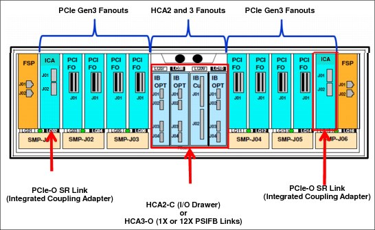
Figure 4-9 CPC drawer front view - coupling links
Previous generation z Systems, in particular z196 and zEC12, use processor books, which provide connectivity for up to eight InfiniBand fanouts per book.
As an example of a possible migration case, assume a one-book zEC12 used as stand-alone coupling facility with all eight fanouts that are used for IFB connectivity. In a 1:1 link migration scenario, this server cannot be migrated to a one CPC drawer z13 because the z13 cannot accommodate more than four InfiniBand fanouts. Furthermore, if FICON Express8 features are carried forward, the total number of InfiniBand fanout are reduced by two. For more information, see 4.6.6, “Fanout considerations” on page 150. In this case, a second CPC drawer is needed to fulfill all IFB connectivity, as shown in Figure 4-10.
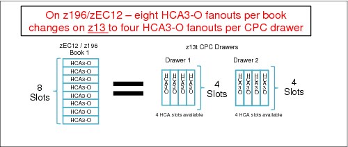
Figure 4-10 HCA3-O Fanouts: z13 versus z196 / zEC12
It is beyond the scope of this book to describe all possible migration scenarios. Always involve subject matter experts (SMEs) to help you to develop your migration strategy.
The following list of considerations can help you assess possible migration scenarios. The objective of this list is to enable migration to z13, supporting legacy coupling where essential, and adopting ICA SR where possible, to avoid the need for more CPC drawers and other possible migration issues.
•The IBM zEnterprise EC12 and BC12 are the last generation of z Systems to support ISC-3, 12x HCA2-O, 1x HCA2-O LR. They also are the last z Systems that can be part of a Mixed CTN.
•Consider Long Distance Coupling requirements first:
– HCA3-O 1x is the only long-distance coupling link that is available on z13. Keep slots free for HCA3-O 1x (LR) where possible.
– ICA SR or HCA3-O 12x should be used for short distance coupling requirements.
•ISC-3 Migration (z13 does not support ISC-3):
– Evaluate current ISC-3 usage (long-, short-distance, coupling data, or timing only) to determine how to fulfill ISC-3 requirements with the links that are available on z13.
– Your options are to migrate from ISC-3 to ICA SR, InfiniBand 12x, or 1x on z13.
– 1:1 Mapping of ISC-3 to Coupling over InfiniBand. On previous servers, the HCA2-C fanouts enable ISC-3 coupling in the I/O Drawer. Two HCA2-C fanouts can be replaced by two 1x fanouts (eight 1x links) or two 12x fanouts (four 12x links).
– ISC-3 supports one CHPID/link. Consolidate ISC-3 CHPIDs into ICA SR or IFB, and uses multiple CHPIDs per link.
•By eliminating FICON Express8 (and thus the need to carry forward the I/O drawers), you can preserve InfiniBand fanout slots for coupling over InfiniBand fanouts. Replace FICON Express8 with FICON Express8S or (depending on your SAN fabric infrastructure) with FICON Express16S.
•Evaluate configurations for opportunities to eliminate or consolidate InfiniBand links:
– Eliminate any redundant links. Two physical links between CPCs is the minimum requirement from a RAS perspective.
– Share logical CHPIDs on a physical IFB link connection to reduce the usage of IFB links in z13 (even multiple sysplexes can share a single link).
– Coupling Link Analysis: Capacity Planning tools and services can help.
•For z13 to z13 links, adopt the new ICA SR coupling link. Use ICA SR channel as much as possible for existing InfiniBand links for z13 to z13 connectivity.
•Install all the ICA SR links that are required to fulfill future short distance coupling requirements:
– When upgrading a CPC to z13, configure the z13 with all the ICA SR coupling links that eventually will be needed (that is, avoid loose piece MES with ICA SR links) in your Parallel Sysplex configuration.
– Consider a plan-ahead configuration. In a multi-CPC configuration, a final approach can be to establish z13 to z13 by using mainly ICA SR connectivity. Even if the links are not used right away, especially within the first z13 migration, most coupling connectivity uses InfiniBand. However, after the second z13 is migrated, coupling connectivity can be moved to ICA SR links.
•Upgrade CPCs with fewer coupling constraints first:
– Consider upgrading CPCs to have sufficient IFB links in the target z13 configuration first (for example, multi-CPC drawer CPCs).
– Test the new ICA SR link on the least constrained CPCs (for example, z/OS Host CPCs that have only the lowest number of links). For the CPCs that are involved in this test that do not have a CF, this might require adding a CF LPAR and ICF engine to one of the CPCs.
– When migrating CPCs with more coupling links to z13, begin by using enough ICA SR links in place of Coupling over InfiniBand (for example, half ICA SR, half 12x) to maintain the CPC footprint (that is, avoid extra CPC drawers).
•Consider replacing two servers, which are close to each other, at the same time. Assess the risk, and, if acceptable, allow immediate replacement of 12x IFB with ICA SR links in z13 peers, thus freeing InfiniBand fanout slots for 1x InfiniBand links.
•Consider (even temporary) increased CHPID/link consolidation on 12x InfiniBand links. For less critical sysplexes (that is, test, development, and QA) that use the IFB3 protocol (see 4.6.4, “HCA3-O (12x IFB) fanout (FC 0171)” on page 148), consider temporary performance reduction when consolidating more than four CHPIDs per 12x link. After the peer system has been migrated to z13, the InfiniBand links can be migrated to ICA SR links.
Coupling link considerations
For more information about changing to InfiniBand or ICA SR coupling links, see Implementing and Managing InfiniBand Coupling Links on System z, SG24-7539, and the Coupling Facility Configuration Options white paper, which can be found at the following website:
Coupling links and Server Time Protocol
All external coupling links can be used to pass time synchronization signals by using Server Time Protocol (STP). STP is a message-based protocol in which timing messages are passed over data links between servers. The same coupling links can be used to exchange time and coupling facility messages in a Parallel Sysplex.
Using the coupling links to exchange STP messages has the following advantages:
•By using the same links to exchange STP messages and coupling facility messages in a Parallel Sysplex, STP can scale with distance. Servers exchanging messages over short distances, such as IFB or ICA SR links, can meet more stringent synchronization requirements than servers that exchange messages over long IFB LR links (distances up to 100 km (62 miles)). This advantage is an enhancement over the IBM Sysplex Timer implementation, which does not scale with distance.
•Coupling links also provide the connectivity that is necessary in a Parallel Sysplex. Therefore, there is a potential benefit of minimizing the number of cross-site links that is required in a multi-site Parallel Sysplex.
Between any two servers that are intended to exchange STP messages, configure each server so that at least two coupling links exist for communication between the servers. This configuration prevents the loss of one link from causing the loss of STP communication between the servers. If a server does not have a CF LPAR, timing-only links can be used to provide STP connectivity.
The z13 server does not support attachment to the IBM Sysplex Timer. A z13 cannot be added into a Mixed Coordinated Timing Network (CTN) and can participate only in an STP-only CTN.
STP recovery enhancement
All coupling host channel adapters (ICA SR, HCA3-O (12xIFB), and HCA3-O LR (1xIFB)) are designed to send a reliable and unambiguous “going away signal.” This signal indicates that the server on which the ICA SR or HCA3 is running is about to enter a failed (check stopped) state. The “going away signal” that is sent by the Current Time Server (CTS) in an STP-only CTN is received by the Backup Time Server (BTS). The BTS can then safely take over as the CTS. The BTS does not have to rely on the previous Offline Signal (OLS) in a two-server CTN, or the Arbiter in a CTN with three or more servers.
This enhancement is exclusive to zEnterprise CPCs. It is available only if you have an ICA SR, HCA3-O (12x IFB), or HCA3-O LR (1x IFB) on the CTS communicating with an ICA SR, HCA3-O (12x IFB), or HCA3-O LR (1x IFB) on the BTS. However, the previous STP recovery design is still available for the cases when a “going away signal” is not received or for failures other than a server failure.
|
Important: For more information about configuring an STP CTN with three or more servers, see the white paper that is found at the following website:
If the guidelines are not followed, it might result in all the servers in the CTN becoming unsynchronized. This condition results in a sysplex-wide outage.
|
For more information about STP configuration, see these books:
•Server Time Protocol Planning Guide, SG24-7280
•Server Time Protocol Implementation Guide, SG24-7281
•Server Time Protocol Recovery Guide, SG24-7380
4.9.3 Pulse Per Second (PPS) input
A Pulse Per Second (PPS) signal can be received from a Network Time Protocol (NTP) server that acts as an external time source (ETS). One PPS port is available on each of the two oscillator cards, which are installed on the CPC drawer backplane (all processor drawers connect to it) of the z13 to provide redundancy for continued operation and concurrent maintenance when a single oscillator card fails. Each oscillator card has a Bayonet Neill-Concelman (BNC) connector for PPS connection support, attaching to two different ETSs. Two PPS connections from two different NTP servers are preferable for redundancy.
The time accuracy of an STP-only CTN is improved by adding an NTP server with the PPS output signal as the ETS device. STP tracks the highly stable accurate PPS signal from the NTP server. It maintains accuracy of 10 µs as measured at the PPS input of the z13 server. If STP uses an NTP server without PPS, a time accuracy of 100 ms to the ETS is maintained. NTP servers with PPS output are available from various vendors that offer network timing solutions.
4.10 Cryptographic functions
Cryptographic functions are provided by the CP Assist for Cryptographic Function (CPACF) and the PCI Express cryptographic adapters. z13 supports the Crypto Express5S feature.
4.10.1 CPACF functions (FC 3863)
FC 38635 is required to enable CPACF functions.
4.10.2 Crypto Express5S feature (FC 0890)
Crypto Express5S is a new feature on z13. On the initial configuration, a minimum of two features are installed. Then, the number of features increases one at a time up to a maximum of 16 features. Each Crypto Express5S feature holds one PCI Express cryptographic adapter. Each adapter can be configured by the installation as a Secure IBM Common Cryptographic Architecture (CCA) coprocessor, as a Secure IBM Enterprise Public Key Cryptography Standards (PKCS) #11 (EP11) coprocessor, or as an accelerator.
Each Crypto Express5S feature occupies one I/O slot in the PCIe I/O drawer, and has no CHPID assigned. However, it uses one PCHID.
4.11 Integrated firmware processor
The integrated firmware processor (IFP) was initially introduced by zEC12 and zBC12 servers. The IFP is reserved for managing a new generation of PCIe features. These new features are installed exclusively in the PCIe I/O drawer:
•zEDC Express
•10GbE RoCE Express
All native PCIe features must be ordered in pairs for redundancy. According to their physical location in the PCIe I/O drawer, the features are assigned to one of the two resource groups (RGs) that are managed by the IFP. If two features of same type are installed, one is managed by resource group 1 (RG 1) and the other feature is managed by resource group 2 (RG 2). This provides redundancy if there is maintenance or a failure in one of the features or resource groups.
The IFP supports the following infrastructure management functions:
•Handle adapter layer functions
•Firmware update
•Error recovery
•Adapter test
•Maintenance functions
For more information about the IFP and RGs, see Appendix G, “Native Peripheral Component Interconnect Express (PCIe)” on page 527.
4.12 Flash Express
The Flash Express cards are supported in a PCIe I/O drawer with other PCIe I/O cards and can be ordered as new (FC 403) or carry-forward (FC 402). They are plugged into PCIe I/O drawers in pairs for availability. Like the Crypto Express5S cards, each card takes up a PCHID, and no HCD/IOCP definition is required. Flash Express subchannels are predefined, and are allocated from the 25 K that is reserved in subchannel set 0.
Flash Express cards are internal to the CPC, and are accessible by using the new z Systems Extended Asynchronous Data Mover (EADM) Facility. EADM is an extension of the Asynchronous Data Mover (ADM) architecture that was used in the past with expanded storage. EADM access is initiated with a Start Subchannel instruction.
z13 supports a maximum of four pairs of Flash Express cards. Only one Flash Express card is allowed per domain. The PCIe I/O drawer has four I/O domains, and can install two pairs of Flash Express cards. Each pair is installed either in the front of PCIe I/O drawers at slots 1 and 14, or in the rear at slots 25 and 33. The Flash Express cards are first plugged into the front slot of the PCIe I/O drawer before being plugged into the rear of drawer. These four slots (1, 14, 25, and 33) are reserved for Flash Express and must not be filled by other types of I/O cards until there is no spare slot.
Figure 4-11 shows a PCIe I/O drawer that is fully populated with Flash Express cards.

Figure 4-11 PCIe I/O drawer that is fully populated with Flash Express cards
4.13 10GbE RoCE Express
RoCE Express (FC 0411) is exclusively in the PCIe I/O drawer and is supported on z13, zEC12, and zBC12. The 10GbE RoCE Express feature has one PCIe adapter. It does not use a CHPID. It is defined by using the input/output configuration program (IOCP) FUNCTION statement or in the hardware configuration definition (HCD). Each feature must be dedicated to an LPAR. In z13, the two ports are supported by z/OS and can be shared by up to 31 partitions (LPARs). In a zEC12 or zBC12, only one of the two ports is supported by z/OS. The 10GbE RoCE Express feature uses an SR laser as the optical transceiver, and supports the use of a multimode fiber optic cable that terminates with an LC Duplex connector. Both point-to-point connections and switched connections with an enterprise-class 10 GbE switch are supported.
|
Switch configuration for RoCE: If the IBM 10GbE RoCE Express features are connected to 10 GbE switches, the switches must support the following requirements:
•Global Pause function enabled
•Priority Flow Control (PFC) disabled
•No firewalls, no routing, and no IEDN
|
The maximum supported unrepeated distance, point-to-point, is 300 meters (984 ft). A client-supplied cable is required. Three types of cables can be used for connecting the port to the selected 10 GbE switch or to the 10GbE RoCE Express feature on the attached server:
•OM3 50 micron multimode fiber optic cable that is rated at 2000 MHz-km that terminates with an LC Duplex connector (supports 300 meters (984 ft))
•OM2 50 micron multimode fiber optic cable that is rated at 500 MHz-km that terminates with an LC Duplex connector (supports 82 meters (269 ft))
•OM1 62.5 micron multimode fiber optic cable that is rated at 200 MHz-km that terminates with an LC Duplex connector (supports 33 meters (108 ft))
4.14 zEDC Express
zEDC Express is an optional feature (FC 0420) that is available on z13, zEC12, and zBC12. It is designed to provide hardware-based acceleration for data compression and decompression.
The feature installs exclusively on the PCIe I/O drawer. Up to two zEDC Express features can be installed per PCIe I/O drawer domain. However, if the domain contains a Flash Express or 10GbE RoCE feature, only one zEDC feature can be installed on that domain.
One to eight features can be installed on the system. There is one PCIe adapter/compression coprocessor per feature, which implements compression as defined by RFC1951 (DEFLATE).
A zEDC Express feature can be shared by up to 15 LPARs.
Adapter support for zEDC is provided by the RG code running on the system IFP. For resilience, there always are two independent RGs on the system, sharing the IFP. It is a preferred practice that a minimum of two zEDC features be installed, one per RG. For the best data throughput and availability, two features per RG, for a total of four features, must be installed.
The Resource Group association is shown in Figure 4-12.
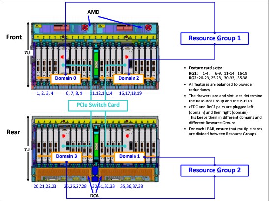
Figure 4-12 Resource Group association within a PCIe I/O drawer
Support of zEDC Express functions is provided by z/OS V2R1 for both data compression and decompression. Support for data recovery (decompression), if zEDC is not available on the system, is provided through software on z/OS V2R1, V1R13, and V1R12 with the appropriate PTFs. Software decompression is slow and uses considerable processor resources, so it is not recommended for production environments.
z/OS guests running under z/VM V6R3 can use the zEDC Express feature. IBM zEnterprise Data Compression (zEDC) for z/OS V2R1 and the zEDC Express feature are designed to support a new data compression function to help provide high-performance, low-latency compression without significant CPU impact. This can help reduce disk usage, provide optimized cross-platform exchange of data, and provide higher write rates for SMF data.
z/OS V2.R1 can use zEDC to compress SMF records. zEDC with z/OS SMF Logger alleviates SMF constraints across the entire lifecycle of a record by using compression technology while storing data in System Logger and reducing Logger CPU usage.
Clients who have large sequential data that uses BSAM/QSAM extended format can use zEDC to help reduce disk space and improve effective bandwidth without significant CPU impact. zEDC also is used by IBM DFSMSdss and IBM DFSMShsm to deliver efficient compression when backing up/restoring data.
IBM 31-bit and 64-bit SDK7 for z/OS Java Technology Edition, Version 7 provides transparent use of the zEDC Express feature. Similarly, the IBM Encryption Facility for z/OS (IBM EF) uses zEDC Express when used with z/OS Java Version 7. For IBM EF users not already using compression, compression with zEDC can provide IBM EF users a reduction of elapsed time and CPU times. This complements the software compression that exists today with Encryption Facility OpenPGP support.
IBM Sterling Connect Direct for z/OS V5R2 can automatically use zEDC Express Accelerator for file compression and decompression as files are transferred cross-platform. Its usage might provide a reduction in the elapsed time to transfer a file from z/OS to z/OS with minimal CPU increase.
1 Higher link speeds might be available for other applications. For more information, see the InfiniBand Trade Association website: http://www.infinibandta.org
2 z13 does not support this link width.
3 Coupling links connectivity is described in 4.9, “Parallel Sysplex connectivity” on page 168.
4 Certain I/O features do not have external ports, such as Crypto Express5S and zEDC
5 Subject to export regulations.
..................Content has been hidden....................
You can't read the all page of ebook, please click here login for view all page.