
CHAPTER 1
CLASSIFICATION
In general terms, propulsion is the act of changing the motion of a body with respect to an inertial reference frame. Propulsion systems provide forces that either move bodies initially at rest or change their velocity or that overcome retarding forces when bodies are propelled through a viscous medium. The word propulsion comes from the Latin propulsus, which is the past participle of the verb propellere, meaning “to drive away.” Jet propulsion is a type of motion whereby a reaction force is imparted to a vehicle by the momentum of ejected matter.
Rocket propulsion is a class of jet propulsion that produces thrust by ejecting matter, called the working fluid or propellant, stored entirely in the flying vehicle. Duct propulsion is another class of jet propulsion and it includes turbojets and ramjets; these engines are more commonly called air‐breathing engines. Duct propulsion devices mostly utilize their surrounding medium as the propellant, energized by its combustion with the vehicle's stored fuel. Combinations of rockets and duct propulsion devices have been attractive for some applications, and one is briefly described in this chapter.
The energy source most commonly used in rocket propulsion is chemical combustion. Energy can also be supplied by solar radiation and by a nuclear reactor. Accordingly, the various propulsion devices in use can be divided into chemical propulsion, nuclear propulsion, and solar propulsion. Table 1–1 lists many important propulsion concepts according to their energy source and type of propellant. Radiant energy may originate from sources other than the sun and theoretically includes the transmission of energy by ground‐based microwaves and laser beams. Nuclear energy originates in transformations of mass within atomic nuclei and is generated by either fission or fusion. Energy sources are central to rocket performance and several kinds, both within and external to the vehicle, have been investigated. The useful energy input modes in rocket propulsion systems are either heat or electricity. Useful output thrust comes from the kinetic energy of the ejected matter and from the propellant pressure on inner chamber walls and at the nozzle exit; thus, rocket propulsion systems primarily convert input energies into the kinetic energy of the exhausted gas. The ejected mass can be in a solid, liquid, or gaseous state. Often, combinations of two or more phases are ejected. At very high temperatures, ejected matter can also be in a plasma state, which is an electrically conducting gas.
Table 1–1 Energy Sources and Propellants for Various Propulsion Concepts
| Energy Sourcea | ||||
| Propulsion Device | Chemical | Nuclear | Solar | Propellant or Working Fluid |
| Turbojet | D/P | Fuel + air | ||
| Turbo–ramjet | TFD | Fuel + air | ||
| Ramjet (hydrocarbon fuel) | D/P | TFD | Fuel + air | |
| Ramjet (H2 cooled) | TFD | Hydrogen + air | ||
| Rocket (chemical) | D/P | TFD | Stored propellant | |
| Ducted rocket | TFD | Stored solid fuel + surrounding air | ||
| Electric rocket | D/P | D/P | Stored propellant | |
| Nuclear fission rocket | TFD | Stored H2 | ||
| Solar‐heated rocket | TFD | Stored H2 | ||
| Photon rocket (big light bulb) | TFND | Photon ejection (no stored propellant) | ||
| Solar sail | TFD | Photon reflection (no stored propellant) | ||
aD/P developed and/or considered practical; TFD, technical feasibility has been demonstrated, but development is incomplete; TFND, technical feasibility has not yet been demonstrated.
1.1 DUCT JET PROPULSION
This class, commonly called air‐breathing engines, comprises devices which entrain and energize air flow inside a duct. They use atmospheric oxygen to burn fuel stored in the flight vehicle. This class includes turbojets, turbofans, ramjets, and pulsejets. These are mentioned here primarily to provide a basis for comparison with rocket propulsion and as background for combined rocket–duct engines, which are mentioned later. Table 1–2 compares several performance characteristics of specific chemical rockets with those of typical turbojets and ramjets. A high specific impulse (which is a measure of performance to be defined later) relates directly to long‐flight ranges and thus indicates the superior range capability of air‐breathing engines over chemical rocket propulsion systems at relatively low earth altitudes. However, the uniqueness of rocket propulsion systems (for example, high thrust to weight, high thrust to frontal area, and thrust nearly independent of altitude) enables flight in rarefied air and exclusively in space environments.
Table 1–2 Comparison of Several Characteristics of a Typical Chemical Rocket Propulsion System and Two‐Duct Propulsion Systems
| Feature | Chemical Rocket Engine or Rocket Motor | Turbojet Engine | Ramjet Engine |
| Thrust‐to‐weight ratio, typical | 75:1 | 5:1, turbojet and afterburner | 7:1 at Mach 3 at 30,000 ft |
| Specific fuel consumption (pounds of propellant or fuel per hour per pound of thrust)a | 8–14 | 0.5–1.5 | 2.3–3.5 |
| Specific thrust (pounds of thrust per square foot frontal area)b | 5000–25,000 | 2500 (low Machc numbers at sea level) | 2700 (Mach 2 at sea level) |
| Specific impulse, typicald (thrust force per unit propellant or fuel weight flow per second) | 270 sec | 1600 sec | 1400 sec |
| Thrust change with altitude | Slight increase | Decreases | Decreases |
| Thrust vs. flight speed | Nearly constant | Increases with speed | Increases with speed |
| Thrust vs. air temperature | Constant | Decreases with temperature | Decreases with temperature |
| Flight speed vs. exhaust velocity | Unrelated, flight speed can be greater | Flight speed always less than exhaust velocity | Flight speed always less than exhaust velocity |
| Altitude limitation | None; suited to space travel | 14,000–17,000 m |
20,000 m at Mach 3 30,000 m at Mach 5 45,000 m at Mach 12 |
a Multiply by 0.102 to convert to kg/(hr‐N).
b Multiply by 47.9 to convert to N/m2.
c Mach number is the ratio of gas speed to the local speed of sound (see Eq. 3–22).
d Specific impulse is a performance parameter defined in Chapter 2.
The turbojet engine is the most common of ducted engines. Figure 1–1 shows its basic elements.

Figure 1–1 Simplified schematic diagram of a turbojet engine.
For supersonic flight speeds above Mach 2, the ramjet engine (a pure duct engine) becomes possible for flights within the atmosphere. Compression is purely gas dynamic and thrust is produced by increasing the momentum of the subsonic compressed air as it passes through the ramjet, basically as is accomplished in the turbojet and turbofan engines but without any compressor or turbine hardware. Figure 1–2 shows the basic components of a ramjet. Ramjets with subsonic combustion and hydrocarbon fuels have an upper speed limit of approximately Mach 5; hydrogen fuel, with hydrogen cooling, raises this to at least Mach 16. Ramjets with supersonic combustion, known as scramjets, have flown in experimental vehicles. All ramjets must depend on rocket or aircraft boosters for initial acceleration to supersonic conditions and operating altitudes, and on oblique shocks to compress and decelerate the entrance air. Applications of ramjets with subsonic combustion include shipboard‐ and ground‐launched antiaircraft missiles. Studies of a hydrogen‐fueled ramjet for hypersonic aircraft looked promising, but as of this writing they have not been properly demonstrated; one supersonic flight vehicle concept combines a ramjet‐driven high‐speed airplane and a one‐ or two‐stage rocket booster for driving the vehicle to its operating altitude and speed; it can travel at speeds up to a Mach number of 25 at altitudes of up to 50,000 m.

Figure 1–2 Simplified diagram of a ramjet with a supersonic inlet (a converging/diverging flow passage).
No truly new or significant rocket technology concepts have been implemented in recent years, reflecting a certain maturity in this field. Only a few new applications for proven concepts have been found, and those that have reached production are included in this edition. The culmination of research and development efforts in rocket propulsion often involves adaptations of new approaches, designs, materials, as well as novel fabrication processes, cost, and/or schedule reductions to new applications.
1.2 ROCKET PROPULSION
Rocket propulsion systems may be classified in a number ways, for example, according to energy source type (chemical, nuclear, or solar) or by their basic function (booster stage, sustainer or upper stages, attitude control, orbit station keeping, etc.) or by the type of vehicle they propel (aircraft, missile, assisted takeoff, space vehicle, etc.) or by their size, type of propellant, type of construction, and/or by the number of rocket propulsion units used in a given vehicle.
Another useful way to classify rockets is by the method of producing thrust. The thermodynamic expansion of a gas in a supersonic nozzle is utilized in most common rocket propulsion concepts. The internal energy of the propellant is converted into exhaust kinetic energy, and thrust is also produced by the pressure on surfaces exposed to the exhaust gases, as will be shown later. This same thermodynamic theory and the same generic equipment (i.e., a chamber plus a nozzle) is used for jet propulsion, rocket propulsion, nuclear propulsion, laser‐thermal and solar‐thermal propulsion, and in some types of electrical propulsion. Totally different methods of producing thrust are used in nonthermal types of electric propulsion. As described below, these electric systems use magnetic and/or electric fields to accelerate electrically charged atoms or molecules at very low gas densities. It is also possible to obtain very small accelerations by taking advantage of the difference in gravitational attraction as a function of earth altitude, but this method is not treated in this book.
The Chinese developed and used solid propellant in rocket missiles over 800 years ago, and military “bombardment rockets” were used frequently in the eighteenth and nineteenth centuries. However, the most significant developments of rocket propulsion took place in the twentieth century. Early pioneers included the Russian Konstantin E. Ziolkowsky, who is credited with the fundamental rocket flight equation and his 1903 proposals to build rocket vehicles. Robert H. Goddard, an American, is credited with the first flight using a liquid propellant rocket engine in 1926. For the history of rockets, see Refs. 1–1 to 1–7.
Chemical Rocket Propulsion
Energy from the combustion reaction of chemical propellants, usually a fuel and an oxidizer, in a high‐pressure chamber goes into heating reaction product gases to high temperatures (typically 2500 to 4100 °C or 4500 to 7400 °F). These gases are subsequently expanded in a supersonic nozzle and accelerated to high velocities (1800 to 4300 m/sec or 5900 to 14,100 ft/sec). Since such gas temperatures are about twice the melting point of steel, it is necessary to cool or insulate all the surfaces and structures that are exposed to the hot gases. According to the physical state of the stored propellant, there are several different classes of chemical rocket propulsion devices.
Liquid propellant rocket engines use propellants stored as liquids that are fed under pressure from tanks into a thrust chamber.1 A typical pressure‐fed liquid propellant rocket engine system is schematically shown in Fig. 1–3. The bipropellant consists of a liquid oxidizer (e.g., liquid oxygen) and a liquid fuel (e.g., kerosene). A monopropellant is a single liquid that decomposes into hot gases when properly catalyzed. Gas pressure feed systems are used mostly on low‐thrust, low‐total‐energy propulsion systems, such as those used for attitude control of flying vehicles, often with more than one thrust chamber per engine. The larger bipropellant rocket engines use one or more turbopump‐fed liquids as shown in Fig. 1–4. Pump‐fed liquid rocket systems are most common in applications needing larger amounts of propellant and higher thrust, such as those in space launch vehicles. See Refs. 1–1 to 1–6.
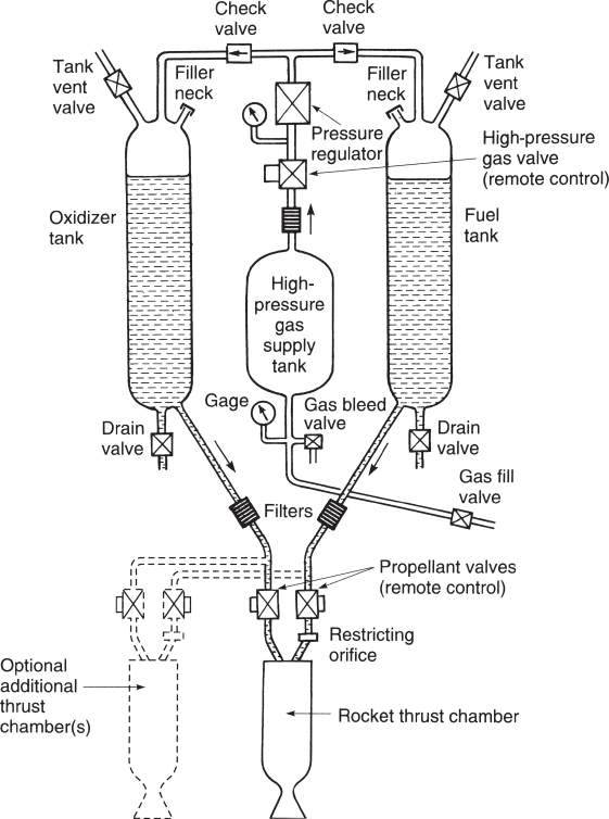
Figure 1–3 Schematic flow diagram of a liquid propellant rocket engine with a gas pressure feed system. The dashed lines show a second thrust chamber, but some engines have more than a dozen thrust chambers supplied by the same feed system. Also shown are components needed for start and stop, controlling tank pressure, filling propellants and pressurizing gas, draining or flushing out remaining propellants, tank pressure relief or venting, and several sensors.

Figure 1–4 Simplified schematic diagram of a liquid propellant rocket engine with one type of turbopump feed system and a separate gas generator, which generates “warm” gas for driving the turbine. Not shown are components necessary for controlling the operation, filling, venting, draining, or flushing out propellants, filters, pilot valves, or sensors. This turbopump assembly consists of two propellant pumps, a gear case, and a high‐speed turbine. Many turbopumps have no gear case.
Chemical propellants react to form hot gases inside the thrust chamber and proceed in turn to be accelerated through a supersonic nozzle from which they are ejected at a high velocity, thereby imparting momentum to the vehicle. Supersonic nozzles consist of a converging section, a constriction or throat, and a conical or bell‐shaped diverging section, as further described in the next two chapters.
Some liquid rocket engines permit repetitive operation and can be started and shut off at will. If the thrust chamber is provided with adequate cooling capacity, it is possible to run liquid rockets for hours, depending only on the propellant supply. A liquid rocket propulsion system requires several precision valves and some have complex feed mechanisms that include propellant pumps, turbines and gas generators. All have propellant‐pressurizing devices and relatively intricate combustion/thrust chambers.
In solid propellant rocket motors2 the ingredients to be burned are already stored within a combustion chamber or case (see Fig. 1–5). The solid propellant (or charge) is called the grain, and it contains all the chemical elements for complete burning. Once ignited, it is designed to burn smoothly at a predetermined rate on all the exposed internal grain surfaces. In the figure, initial burning takes place at the internal surfaces of the cylinder perforation and at the four slots. The internal cavity expands as propellant is burned and consumed. The resulting hot gases flow through the supersonic nozzle to impart thrust. Once ignited, motor combustion is designed to proceed in an orderly manner until essentially all the propellant has been consumed. There are no feed systems or valves. See Refs. 1–6 to 1–9.
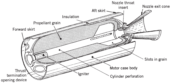
Figure 1–5 Simplified perspective three‐quarter section view of a typical solid propellant rocket motor with the propellant grain bonded to the case and to the insulation layer, and with a conical exhaust nozzle. The cylindrical case with its forward and aft hemispherical domes forms a pressure vessel containing the combustion chamber pressure.
Adapted with permission from Ref. 12–1.
Liquid and solid propellants, together with the propulsion systems that use them, are discussed in Chapters 6 to 11 and 12 to 15, respectively. Rocket propulsion selection systems, for both liquid and solid propellants, are compared in Chapter 19.
Gaseous propellant rocket engines use a stored high‐pressure gas, such as air, nitrogen, or helium, as working fluid. Such stored gases require relatively heavy tanks. These cold gas thrusters were used in many early space vehicles for low‐thrust maneuvers and for attitude‐control systems, and some are still used today. Heating the gas with electrical energy or by the combustion of certain monopropellants in a chamber improves their performance, and this has often been called warm gas propellant rocket propulsion. Chapter 7 reviews gaseous propellants.
Hybrid propellant rocket propulsion systems use both liquid and solid propellant storage. For example, if a liquid oxidizing agent is injected into a combustion chamber filled with a solid carbonaceous fuel grain, the chemical reaction produces hot combustion gases (see Fig. 1–6). They are described further in Chapter 16. Several have flown successfully.

Figure 1–6 Schematic diagram of a typical hybrid rocket engine. The relative positions of the oxidizer tank, high‐pressure gas tank, and the fuel chamber with its nozzle depend on the particular vehicle design.
Combinations of Ducted Jet Engines and Rocket Engines
The Tomahawk surface‐to‐surface missile uses a sequenced two‐stage propulsion system. The solid propellant rocket booster lifts the missile away from its launch platform and is discarded after its operation. A small turbojet engine then sustains their low‐level flight at nearly constant subsonic speed toward the target.
Ducted rocket propulsion systems, sometimes called air‐augmented rocket propulsion systems, combine the principles of rocket and ramjet engines; they give higher performance (specific impulse) than chemical rocket engines but can only operate within the earth's atmosphere. Usually, the term air‐augmented rocket denotes mixing of air with the rocket exhaust (made fuel rich for afterburning) in proportions that enable the propulsion device to retain those characteristics that typify rocket engines, for example, high static thrust and high thrust‐to‐weight ratio. In contrast, the ducted rocket is often like a ramjet in that it must be boosted to operating speed and uses the rocket components more as a fuel‐rich gas generator (liquid or solid).
The action of rocket propulsion systems and ramjets can be combined. An example of these two are propulsion systems operating in sequence and then in tandem and yet utilizing a common combustion chamber volume, as shown in Fig. 1–7. Such a low‐volume configuration, known as an integral rocket–ramjet, has been attractive for air‐launched missiles using ramjet propulsion. The transition from rocket engine to ramjet requires enlarging the exhaust nozzle throat (usually by ejecting rocket nozzle parts), opening the ramjet air inlet–combustion chamber interface, and following these two events with a normal ramjet starting sequence.

Figure 1–7 Simplified diagram of an air‐launched missile with integral rocket–ramjet propulsion. After the solid propellant has been consumed in boosting the vehicle to flight speed, the rocket combustion chamber becomes the ramjet combustion chamber with air burning the ramjet liquid fuel. Igniter and steering mechanisms are not shown.
A solid fuel ramjet uses grains of solid fuel that gasify or ablate and then react with air. Good combustion efficiencies have been achieved with a patented boron‐containing solid fuel fabricated into grains similar to a solid propellant rocket motor and burning in a manner similar to a hybrid rocket propulsion system.
Nuclear Rocket Engines
These are basically a type of liquid propellant rocket engine where the power input comes from a single nuclear reactor and not from any chemical combustion. During the 1960s an experimental rocket engine with a nuclear fission graphite reactor was built and ground tested with liquid hydrogen as the propellant. It delivered an equivalent altitude specific impulse (this performance parameter is explained in Chapter 2) of 848 sec, a thrust of over 40,000 lbf at a nuclear reactor power level of 4100 MW with a hydrogen temperature of 2500 K. No further ground tests of nuclear fission rocket engines have been undertaken.
Public concerns about any ground and/or flight accident with the inadvertent spreading of radioactive materials in the Earth's environment have caused the termination of nuclear rocket engine work. It is unlikely that nuclear rocket engines will be developed in the next few decades and therefore no further discussion is given in here. Our Eighth Edition has additional information and references on nuclear propulsion.
Electric Rocket Propulsion
Electric propulsion has been attractive because of its comparatively high performance, producing desired amounts thrust with moderately low propellant utilization, but they are limited to relatively low thrusts by existing electrical power supplies. This type of propulsion is much too low for earth launches and atmospheric fight because it requires rather massive and relatively inefficient power sources (but in spacecraft they can often be shared with other subsystems). Unlike chemical propulsion, electric propulsion utilizes energy sources (nuclear, solar radiation, or batteries) not contained in the propellant being utilized. The thrust is usually quite low, levels typical of orbit maintenance (0.005 to 1 N). In order to accomplish significant increases in vehicle velocity, it is necessary to apply such low thrusts (and their small accelerations) during times considerably longer than with chemical propulsion, some for months and even years (see Ref. 1–10 and Chapter 17).
Of the three basic electric types, electrothermal rocket propulsion most resembles the previously discussed liquid‐propellant chemical rocket units; a propellant is heated electrically (with solid resistors called resistojets or electric arcs called arcjets), and the hot gas is then thermodynamically expanded through a supersonic nozzle (see Fig. 1–8). These electrothermal thrusters typically have thrust ranges of 0.01 to 0.5 N, with exhaust velocities of 1000 to 7800 m/sec; they use ammonium, hydrogen, nitrogen, or hydrazinede composition products as the propellant.

Figure 1–8 Simplified schematic diagram of arcjet thruster. The arc plasma temperature is very high (perhaps 15,000 K) and the anode, cathode, and chamber will get hot (1000 K) due to heat transfer.
The two other types—the electrostatic or ion propulsion thrusters and the electromagnetic or magnetoplasma thrusters—accomplish propulsion by different means, and no thermodynamic gas expansion in a nozzle is necessary. Both work only in a vacuum. In an ion thruster (see Fig. 1–9) the working fluid (typically, xenon) is ionized by stripping off electrons, and then the heavy ions are accelerated to very high velocities (2000 to 60,000 m/sec) by means of electrostatic fields. The ions are subsequently electrically neutralized by combining them with emitted electrons to prevent the buildup of a “space charge” on the vehicle.

Figure 1–9 Simplified schematic diagram of a typical ion thruster, showing the approximate distribution of the electric power by the width of the arrow.
In electromagnetic thrusters, a plasma (an energized gaseous mixture of ions, electrons, and neutral particles) is accelerated by the interaction between electric currents and perpendicular magnetic fields and this plasma is then ejected at high velocities (1000 to 75,000 m/sec). There are many different types and geometries. The Hall‐effect thruster, a relatively new entry, may also be considered as electrostatic (see Chapter 17). A simply configured, pulsed electrical thruster with a solid (stored) propellant is shown in Fig. 1–10; it has been used for spacecraft attitude control (Ref. 1–10).
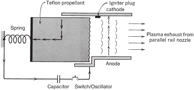
Figure 1–10 Simplified diagram of a pulsed plasma thruster with self‐induced magnetic acceleration. When the capacitor is discharged, an arc is struck at the left side of the rails. The high arc current closes the loop, thus inducing a magnetic field. The action of the current and the magnetic field causes the plasma to be accelerated at right angles to both the magnetic field and the current in the direction of the rails. Each time the arc is created, a small amount of solid propellant (Teflon) is vaporized and converted to a small plasma cloud, which (when ejected) gives a small pulse of thrust. Actual units can operate with many pulses per second.
Other Rocket Propulsion Concepts
One concept is the solar thermal rocket; it has large‐diameter optics to concentrate the sun's radiation (e.g., with lightweight precise parabolic mirrors or Fresnel lenses) onto a receiver or optical cavity, see Ref. 1–11. Figure 1–11 shows one embodiment and some data is given in Table 2–1. The receiver is made of high‐temperature metal (such as tungsten or rhenium) and has a heat exchanger that heats the working fluid, usually hydrogen, up to perhaps 2500 °C; the hot gas is then exhausted through one or more nozzles. The large reflective mirror must be pointed toward the sun, and this requires orientation adjustments if the spacecraft orbits around the Earth or other planets. Performance can be two to three times higher than that of chemical rockets and thrust levels are low (1 to 10 N). Since large lightweight optical elements cannot withstand drag forces without deformation, such units are deployed outside the atmosphere. Contamination is negligible, but storage or refueling of liquid hydrogen is a challenge. Problems being investigated include rigid, lightweight mirror or lens structures; operational lifetimes; and minimizing hydrogen evaporation and heat losses to other spacecraft components. An experimental solar‐thermal rocket propulsion system flew in a satellite in 2012. It has not been approved for a production application (as of 2015) to the authors' knowledge.

Figure 1–11 Schematic diagram of a solar thermal rocket concept.
The solar sail is another concept. It is basically a large photon reflecting surface. The power source for the solar sail is external to the vehicle (see Ref. 1–12), but the vehicle can only move away from the sun. Concepts for transmitting radiation energy (by lasers or microwaves) from ground stations on Earth to satellites have been proposed but not yet tested.
International Rocket Propulsion Effort
Active development and/or production of rocket propulsion systems have been under way in more than 30 different countries. A few foreign rocket units are mentioned in this book together with their characteristics and with references to the international rocket literature. Although most of the data in this book are taken from U.S. rocket experiences, this is not intended to minimize the significance of foreign achievements.
At the time of this writing, the only joint major international program has been the International Space Station (ISS), a multiyear cooperative effort with major contributions from the United States and Russia and active participation by several other nations. This manned orbital space station is used for conducting experiments and observations on a number of research projects. See Ref. 1–13.
1.3 APPLICATIONS OF ROCKET PROPULSION
Because rocket propulsion can reach performances unequaled by other prime movers, it has its own field of applications and does not usually compete with other propulsion devices. Selection of the best rocket propulsion system type and design for any given application is a complex process involving many factors, including system performance, reliability, cost, propulsion system size, and compatibility, as described in Chapter 19. Examples of important applications are given below and some are discussed further in Chapter 4.
Space Launch Vehicles
Since 1957 there have been numerous space launch attempts with a better than 95% success record. Space launch vehicles or space boosters can be broadly classified as expendable or recoverable/reusable, by the type of propellant (storable or cryogenic liquid or solid propellants), number of stages (single‐stage, two‐stage, etc.), size/mass of payloads or vehicles, and as manned or unmanned. There are many different missions and payloads for space launch vehicles. Discussed below are the following categories: commercial missions (e.g., communications), military missions (e.g., reconnaissance), nonmilitary missions (e.g., weather observation), and space exploration missions (e.g., flights to the planets).
Each space launch has a specific space flight objective, such as an Earth orbit or a moon landing. See Ref. 1–14. It uses between two and five stages, each with its own propulsion systems and each usually fired sequentially after the lower stage is expended. Selection for the number of stages is based on the specific space trajectory, the number and types of maneuvers, the energy content of a unit mass of the propellant, the payload size, as well as other factors. The initial stage, usually called the booster stage, is the largest; this stage is then separated from the ascending vehicle before the second‐stage propulsion system is ignited and operated. As explained in Chapter 4, adding extra stages may permit significant increases in the payload (such as more scientific instruments or more communications gear).
Each stage of a multistage launch vehicle is essentially a complete vehicle in itself and carries its own propellant, its own rocket propulsion system or systems, and its own control system. Once the propellant of a given stage is expended, its remaining mass (including empty tanks, cases, structure, instruments, etc.) is no longer useful to succeeding stages. By dropping off this mass, it is possible to accelerate the final stage with its payload to a higher terminal velocity than would be attained if multiple staging were not used. Both solid propellant and liquid propellant rocket propulsion systems have been amply utilized in low Earth orbit missions.
Figure 1–12 shows the Delta IV HEAVY lift space launch vehicle at takeoff. Its propellants are liquid oxygen/liquid hydrogen (LOX/LH2) in all its main engines. Its booster engine, the Aerojet Rocketdyne RS‐68A, is shown in Figs. 6–9a and 6–9b and data is in Table 11–2; its second‐stage engine, the Aerojet Rocketdyne RL‐10B‐2 LOX/LH2 (24,750 lbf thrust) is shown in Fig. 8–17 and data is in Table 8–1. The two liquid propellant strap‐on booster pods (with the same booster engine) are removed for launching smaller payloads. Figure 1–13 shows the Atlas V space launch vehicle. Its booster engine is the Russian (Energomash) RD‐180, it has Aerojet solid propellant strap‐on boosters, and the upper stage engine is the Aerojet Rocketdyne RL 10A‐4‐2 LOX/LH2 engine. The Russian (Energomash) LOX/kerosene RD‐180 engine is shown in Ref. 1–2 as its Figure 7.10–11 and data is in its Table 7.10–2. In both of these launch vehicles the payload is carried on top of the second stage, which has its own propulsion set of small thrusters. Table 1–3 gives data for the larger propulsion systems in these two U.S. launch vehicles. Not shown in Table 1–3 are two additional stage separation systems for the Delta IV HEAVY space launch vehicle. One consists of a set of small solid propellant rocket motors that are installed in the two outboard boosters; one quarter of these motors are installed under each of the nozzle housings and one quarter under each nose fairing at the outboard booster stages. Their purpose is to move two outboard boosters (just after thrust termination) from the center or core booster (which continues to operate) and thus prevent any collision. These separation solid propellant motor boosters have a relatively high thrust of very short duration.

Figure 1–12 Delta IV HEAVY lift space launch vehicle. The center liquid propellant booster stage has a Pratt & Whitney Rocketdyne RS‐68A rocket engine (LOX/LH2). The two strap‐on stages each use the same engine. See Figs. 6–9a and 6–9b.
Courtesy Aerojet‐Rocketdyne.

Figure 1–13 Atlas V space launch vehicle with three (or five) strap‐on stages using Aerojet solid rocket motors and a central Energomash (Russia) RD‐180 liquid propellant booster rocket engine running on LOX/kerosene. See Table 1–3 for key parameters.
Courtesy United Launch Alliance.
Table 1–3 Major Propulsion Systems for Two U.S. Launch Vehicles
| Vehicle | Propulsion System Designation (Propellant) | Stage | No. of Propulsion Systems per Stage | Thrust (lbf/kN) per Engine/Motor | Specific Impulse (sec) | Mixture Ratio, Oxidizer to Fuel Flow | Chamber Pressure (psia) | Nozzle Exit Area Ratio | Inert Engine Mass (lbm/kg) |
| DELTA IV HEAVY | RS‐68A (LOX/LH2) | 1 | 1 or 3 | 797,000/3548a | 411a | 5.97 | 1557 | 21.5:1 | 14,770/6,699 |
| RL 10B‐2 (LOX/LH2) | 2 | 1 | 702,000/3123b, c | 362b | 5.88 | 633 | 285:01:00 | 664 lbm | |
| 24,750/0.110a | 465.5a | ||||||||
| ATLAS V | Solid Booster | 0 | Between 1d and 5 | 287,346/1.878b each | 279.3b | N/A | 3722 | 16:1c | 102,800 lbm (loaded) |
| RD‐180d (LOX/Kerosene) | 1 | 1 | 933,400/4.151a | 310.7b | 2.72 | 610 | 36.4:1 | 12,081/5,480 | |
| RD 10A‐4‐2 (LOX/LH2) | 2 | 1 or 2 | 860,200/3.820b, c | 337.6a | 4.9–5.8 | 84.1:1 | 5330 kg | ||
| 22,300/99.19a | 450.5a | 370/168 |
aVacuum value.
bSea‐level value.
cAt ignition.
dRussian RD‐180 engine has 2 gimbal‐mounted thrust chambers.
Also not listed in Table 1–3 is an attitude control system for the second stage of the Delta IV HEAVY. It has 12 small restartable monopropellant hydrazine thrusters that provide pitch, yaw, and roll control forces to this upper stage during the powered flight (from the RL‐10B‐2) and during the unpowered portion of this upper stage. These thrusters and the separation motors are not evident in Fig. 1–12.
The U.S. Space Shuttle, which was retired in 2011, provided the first reusable spacecraft that could glide and land on a runway. Figure 1–14 shows the basic configuration of the Space Shuttle at launch, which consisted of two stages, the booster, the orbiter stage, and an external tank. It shows all the 67 rocket propulsion systems of the shuttle. These consisted of 3 main engines (LOX/LH2 of 470,000 lbf vacuum thrust each, see Chapter 7 for chemical nomenclature), 2 orbital maneuvering engines (N2O4/MMH of 6,000 vacuum thrust each), 38 reaction control primary thrusters (N2O4/MMH of 870 lbf vacuum thrust each), 6 reaction control Vernier thrusters (N2O4/MMH of 25 lbf vacuum thrust each), 2 large segmented booster solid propellant motors (composite solid propellant of 3.3 × 10⁶ lbf thrust at sea level each), and 16 stage separation rocket motors (with composite solid propellants of 22,000 lbf vacuum thrust each, operating for 0.65 sec); they were activated after thrust termination of the boosters in order to separate them from the external tank. The orbiter was the reusable vehicle, a combination space launch vehicle, spacecraft, and glider for landing. The two solid propellant strap‐on rocket motors were then the largest in existence; they were equipped with parachutes for sea recovery of the burned‐out motors. The large LO2/LH2 external tank was jettisoned and expended just before orbit insertion (see Ref. 1–15). The Space Shuttle accomplished both civilian and military missions, placing astronauts and satellites in orbit, undertaking scientific exploration, supplying the International Space Station, and repairing, servicing, and retrieving satellites. Today, the retired orbiters (the winged vehicles of the Space Shuttle) are on museum displays. At the time of this writing (2015), the National Aeronautics and Space Administration (NASA) had awarded the initial research and development (R&D) contracts in several critical areas for a new large manned space flight vehicle identified as Orion and as SLS (Space Launch System).

Figure 1–14 Simplified diagrams of the original Space Shuttle vehicle. The shuttle orbiter—the delta‐winged vehicle about the size of a medium‐range jet liner—was a reusable, cargo‐carrying, spacecraft–airplane combination that took off vertically and landed horizontally as a glider. Each shuttle orbiter was designed for a minimum of 100 missions and could carry as much as 65,000 lb of payload to a low Earth orbit, and a crew of up to four members. It could return up to 25,000 lb of payload back to earth. NASA's new manned Space Launch System plans using a modified Space Shuttle engine (see Fig. 6–1) designated as the RS‐25.
A new generation of manned space flight vehicles is currently being developed by several entrepreneurial U.S. and foreign companies, some with private capital. They are aimed at future commercial markets that include sending tourists into space forays. All are based on reusable spacecraft, some with reusable launch vehicles, some with vertical and some with horizontal takeoff or landing. A number of suborbital flights have already been accomplished by test pilots using new winged vehicles. It is too early to predict which of these organizations will be successful in commercializing manned space flight. Some new companies have already developed structures and engines for practical “low‐cost” launch vehicles; these are, at the time of this writing, being routinely used for transporting supplies to the International Space Station (which is in a low Earth orbit). To bring down costs, the first stage of future launch vehicles will need to be recoverable and reusable.
A single‐stage‐to‐orbit vehicle, an attractive concept because it avoids the costs and complexities of staging, would be expected to have improved reliability (simpler structures, fewer components). However, its envisioned payload has been too small for economic operation. To date efforts at developing a rocket‐propelled single‐stage‐to‐orbit vehicle have not been successful.
Spacecraft
Depending on their mission, spacecraft can be categorized as Earth satellites, lunar, interplanetary, and trans‐solar types, and/or as manned and unmanned spacecraft. Reference 1–16 lists over 20,000 satellites and categorizes them as satellites for communications, weather, navigation, scientific exploration, deep space probes, observation (including radar surveillance), reconnaissance, and other applications. Rocket propulsion is needed for both primary propulsion (i.e., acceleration along the flight path, such as for ascents, orbit insertion, or orbit change maneuvers) and for secondary propulsion functions in these vehicles. Some of the secondary propulsion functions are attitude control, spin control, momentum wheel and gyro unloading, rendezvous in space, stage separation, and for the settling of liquids in tanks. Spacecraft need a variety of different rocket propulsion systems and some thrusters can be very small. For spacecraft attitude control about three perpendicular axes, each in two rotational directions, the system must allow the application of pure torque for six modes of angular freedom, thus requiring a minimum of 12 thrusters. Some missions require as few as 4 to 6 thrusters, whereas the more complex manned spacecraft have 20 to 50 thrusters in all of their stages. Often, the small attitude control rockets must give pulses or short bursts of thrust, necessitating thousands of restarts. See Section 6.7 and Ref. 1–17.
A majority of spacecraft and space launch vehicles use liquid propellant engines for principal propulsion because of their better performance. Liquid propellants are used as both primary and secondary propulsion systems. A few vehicles have used solid propellant rocket motors for booster stages and some for orbit injection. Some spacecraft operate successfully with electrical propulsion for attitude control. Recently electrical propulsion (EP) systems have also been used for some primary and secondary spacecraft propulsion missions in long‐duration space flights. Because of their low thrust, space operations/maneuvers with EP require relatively longer times to reach desired velocity increases. For example, transfer from a low Earth orbit to a geosynchronous orbit may take as long as two or three months compared to a few hours with chemical propulsion systems. See Chapter 17. Designs utilizing all‐electric propulsion systems for upper stages are a relatively recent trend.
Micropropulsion is a new designation for thrust levels applicable to small spacecraft of less than 100 kg, or 220 lbm. See Ref. 1–18. It encompasses a variety of different propulsion concepts, such as certain very low thrust liquid mono‐ and bipropellant rocket engines, small gaseous propellant rocket engines, several types of electrical propulsion systems, and emerging advanced versions of these. Many are based on recent fabrication techniques for very small components (valves, thrusters, switches, insulators, or sensors) by micromachining and electromechanical processes.
Military and Other Applications
Military applications can be classified as shown in Table 1–4. Rocket propulsion for new U.S. missiles is presently based almost exclusively on solid propellant rocket motors. These can be strategic missiles, such as long‐range ballistic missiles (800 to 9000 km range), which are aimed at military targets within an enemy country, or tactical missiles, which are intended to support or defend military ground forces, aircraft, or navy ships. Table 1–5 shows some preferred rocket propulsion systems for selected applications.
Table 1–4 Selected Military Applications Using Rocket Propulsion Systems
| Category | Vehicle/System | Comments/Examples |
| Military Satellites |
Reconnaissance/Observation Secure communications Early warning of ICBM launches |
Rely on existing vehicles, such as Delta IV or Delta II and Atlas V |
| Strategic Weapons |
ICBM—silo launched ICBM—submarine launched Cruise missile (subsonic flight) |
Minuteman III; Trident; SPRMs; 5000 to 9000 km range; Tomahawk with SPRM booster and turbofan engine |
|
Surface‐to‐Surface Tactical Weapons |
Intermediate range ballistic missile Battlefield support (very short range) Ship launched to ship or shore Small shoulder‐fired missile Wire‐guided small missile |
Pershing II (2 stages) Guided or unguided All use SPRM and single‐stage, Redeye is a surface‐to‐air shoulder‐fired missile |
|
Surface‐to‐Air and Surface‐to‐Incoming‐Missile Tactical weapons |
Local area defense (e.g., airfield) Large area defense Battlefield support Shoulder‐fired small missile Ship defense |
Standard missile, Patriot missile, Multistage vehicle with SPRM booster and LPRE divert top stage Guided or unguided SPRM, Redeye Unwinding wire to control flight path of local battlefield missile |
| Air‐to‐Surface Missiles |
Short range Long range |
All use SPRMs Larger guided missiles |
| Air‐to‐Air Missiles | Carried under aircraft wings | Guided, SPRM, Phoenix, Sparrow |
|
Specialized Weapons or Devices |
Antitank missiles Antisubmarine missiles Anti‐radar missiles Torpedo propulsion Rocket‐assisted artillery Aircraft pilot seat ejection |
With armor piercing warhead Hawk, TOW, SPRM Subroc, SPRM Homing air launched SPRM Gas generator, SPRM Up to 20,000g0 in gun barrel, increased range Emergency maneuver, SPRM |
ICBM, intercontinental ballistic missile; LPRE, liquid propellant rocket engine; SPRM, solid propellant rocket motor.
Table 1–5 Selected Examples of Propulsion Characteristics of Rocket Applications
| Application | Type of Propellant | Thrust Profile | Typical Firing Duration | Maximum Accelerationa |
| Large space launch vehicle | Liquid or cryogenic liquid | Nearly constant thrust | 2–8 min | 1.2–6 g0 |
| Strap‐on booster | Solid or liquid | 100,000 to 3,300,000 lbf | ½ to 2 min | 1.2 to 3 g0 |
| Spent strap‐on stage separation | 4 to 8 SPRMs | 10,000 to 20,000 lbf each | Less than 1 sec | N. A. |
| Antiaircraft or antimissile‐missile | Solid, some with liquid terminal divert stage | High thrust boost, decreasing thrust sustain phase; high thrust divert | 2–75 sec each | 5 to 20 g0, but can be up to 100 g0 |
| Spacecraft orbit maneuvers and/or maintenance | Storable liquid or cryogenic liquid; electric propulsion | Multiple restarts in space; can be pulsed | Up to 10 min cumulative duration | 0.2–6 g0 |
| Air‐launched guided missile | Solid | High thrust boost phase with low thrust or decreasing thrust for sustain phase; sometimes 2 pulses | Boost: 2–5 sec Sustain: 10–30 sec | Up to 25 g0 |
| Battlefield support—surface launched | Solid | Decreasing thrust | Up to 2 min each stage | Up to 10 g0 |
| Rocket‐assisted projectile, gun launched | Solid | Constant or decreasing thrust | A few sec | Up to 20,000 g0 in gun barrel |
| Spacecraft attitude control—large vehicles | Storable liquid (monopropellant or bipropellant); electric propulsion; xenon | Many restarts (up to several thousands); pulsing | Up to several hours cumulative duration | Less than 0.1 g0 |
| Spacecraft attitude control—small vehicle | Electric propulsion; Cold or warm gas or storable liquid. | Same | Up to several hours cumulative | Same |
| Reusable main engines for Space Shuttle | Cryogenic liquid (O2/H2) | Variable thrust, many flights with same engine | 8 min, over 7 hr cumulative in several missions | |
| Lunar landing | Storable bipropellant | 10:1 thrust variation | 4 min | Several g0 |
| Weather sounding rocket | Solid | Single burn period—often decreasing thrust | 5–30 sec | Up to 15 g0 |
| Antitank | Solid | Single burn period | 0.2–3 sec | Up to 20 g0 |
ag0 is acceleration of gravity at the Earth's surface = 9.8066 m/sec2 or 32.17 ft/sec2.
The term surface launch can mean launching from the ground, the ocean surface (from a ship), or from underneath the sea (submarine launch). Some tactical missiles, such as the air‐to‐surface short‐range attack missile (SRAM), have a two‐pulse solid propellant motor, where two separate insulated grains of different solid properties are in the same motor case; the time interval before starting the second pulse can be timed to control the flight path or speed profile. Many countries now have tactical missiles in their military inventories, and many of these countries have the capability to produce their own vehicles and their rocket propulsion systems.
Applications that were popular 40 to 70 years ago but are no longer active include liquid propellant rocket engines for propelling military fighter aircraft to altitude, assisted takeoff rocket engines and rocket motors, and superperformance rocket engines for augmenting the thrust of an aircraft jet engine.
Other applications of rocket propulsion systems to space operations include communication satellites—these have been successfully deployed for many years providing relays of telephone and television signals between Earth stations; this application is managed and operated by commercial organizations. Other countries also have their own satellite‐based communications. The U.S. government sponsored programs that include weather satellites and the now ubiquitous Global Positioning System (GPS). Examples of space exploration include missions to the planets and/or into deep space, such as the Voyager mission and the MESSENGER program. A good number of these missions and probes were developed by NASA's Jet Propulsion Laboratory; they use the multiple thrusters from a monopropellant hydrazine reaction control system. Another application is for suborbital winged space vehicles for space tourism; as of 2014, two such vehicles (privately financed) have been flown in experimental versions (see Fig. 16–3).
REFERENCES
- 1–1 E. C. Goddard and G. E. Pendray (Eds), The Papers of Robert H. Goddard, three volumes, McGraw‐Hill Book Company, 1970, 1707 pages. It includes the pioneering treatise “A Method of Reaching Extreme Altitudes” originally published as Smithsonian Miscellaneous Collections, Vol. 71, No. 2, 1919.
- 1–2 G. P. Sutton, History of Liquid Propellant Rocket Engines, published by AIAA, 2006, 911 pages.
- 1–3 B. N. Yur'yev (Ed), Collected Works of K. E. Tsiolkowski, Vols. 1–3, USSR Academy of Sciences, 1951; also NASA Technical Translation F‐236, April 1965.
- 1–4 H. Oberth, Die Rakete zu den Planetenräumen (By Rocket to Planetary Space), R. Oldenburg, Munich, 1923 (in German), a classical text.
- 1–5 W. von Braun and F. Ordway, History of Rocketry and Space Travel, 3rd ed., Thomas Y. Crowell, New York, 1974.
- 1–6 L. H. Caveny, R. L. Geisler, R. A. Ellis, and T. L. Moore, “Solid Enabling Technologies and Milestones in the USA,” Journal of Propulsion and Power, Vol. 19, No. 6, Nov.–Dec. 2003, AIAA, pp. 1038–1066.
- 1–7 A. M. Lipanov, “Historical Survey of Solid Propellant Rocket Development in Russia,” Journal of Propulsion and Power, Vol. 19, No. 6. Nov.–Dec. 2003, pp. 1063–1088.
- 1–8 AGARD Lecture Series 150, Design Methods in Solid Rocket Motors, AGARD/NATO, Paris, April 1988.
- 1–9 A. Davenas, Solid Rocket Propulsion Technology, Pergamon Press, London (originally published in French), revised edition 1996.
- 1–10 C. Zakrzwski et al., “On‐Orbit Testing of the EO–1 Pulsed Plasma Thruster.” AIAA2002–3973, Reston, VA, 2002. http://eo1.gsfc.nasa.gov/new/validationReport/Technology/Documents/Summaries/08‐PPT_Rev‐0.pdf
- 1–11 T. Nakamura et al., “Solar Thermal Propulsion for Small Spacecraft—Engineering System Development and Evaluation,” Report PSI‐SR‐1228, July 2005.
- 1–12 T. Svitek et al., “Solar Sails as Orbit Transfer Vehicle—Solar Sail Concept Study,” Phase II Report, AIAA paper 83–1347, 1983.
- 1–13 NASA International Space Station (A resource on the ISS by NASA; includes operational use, wide range of background material, archives, image gallery and planned missions). www.nasa.gov/station‐34k
- 1–14 S. J. Isakowitz, J. B. Hopkins, and J. P. Hopkins, International Reference Guide to Space Launch Systems, 4th ed., AIAA, 2004, 596 pages.
- 1–15 National Aeronautics and Space Administration (NASA), National Space Transportation System Reference, Vol. 1, Systems and Facilities, U.S. Government Printing Office, Washington, DC, June 1988; a description of the Space Shuttle.
- 1–16 A. R. Curtis (Ed), Space Satellite Handbook, 3rd ed., Gulf Publishing Company, Houston, TX, 1994, 346 pages.
- 1–17 G. P. Sutton, “History of Small Liquid Propellant Thrusters,” presented at the 52nd JANNAF Propulsion Meeting, May 2004, Las Vegas, NE, published by the Chemical Propulsion Information Analysis Center, Columbia, Maryland, June 2004.
- 1–18 M. M. Micci and A. D. Ketsdever, Micropropulsion for Small Spacecraft, Progress in Aeronautics and Astronautics Series, Vol. 187, AIAA, 2000, 477 pages.