
CHAPTER 8
THRUST CHAMBERS
Thrust chambers are an essential subassembly of liquid propellant rocket engines. This chapter describes chemical rocket thrust chambers and their components, including the topics of ignition and heat transfer. In the thrust chamber liquid propellants are metered, injected, atomized, vaporized, mixed, and burned to form hot reaction gaseous products, which are subsequently accelerated and ejected at supersonic velocities (see Refs. 6–1, 6–2, and 8–1). Chamber assemblies (e.g., Figs. 8–1 and 8–2) comprise one or more injectors, a combustion chamber, a supersonic nozzle, and various mounting provisions. All these parts have to withstand the extreme combustion environments and various forces, including those that transmit thrust to the vehicle. An ignition system must be also present when nonspontaneously ignitable propellants are utilized. Some thrust chamber assemblies also include integrally mounted propellant valves and occasionally thrust vector control devices, as described in Chapter 18. Table 8–1 presents data on five thrust chambers each having different kinds of propellants, cooling methods, injectors, feed systems, thrust levels, and/or nozzle expansions. Some engine parameters are also listed. Several terms used in this table are explained later in this chapter.

Figure 8–1 Construction of an early regeneratively cooled tubular thrust chamber using a kerosene‐type fuel with liquid oxygen, as originally used in the Thor missile. The nozzle throat inside diameter is about 15 in. The sea‐level thrust was originally 120,000 lbf, but was uprated to 135,000, then 150,000, and finally to 165,000 lbf by increasing the flow and chamber pressure and strengthening and modifying the hardware. The cone‐shaped nozzle exit was replaced by a bell‐shaped nozzle exit. Later in this chapter, Fig. 8–9 shows how the fuel flows down through every other cooling jacket tube and returns through the adjacent tube before flowing into the injector. Figure 8–5 shows a similar injector.
Developed by Rocketdyne and licensed to Rolls Royce, England.

Figure 8–2 Simplified half‐section of one of the two thrust chambers of the orbital maneuvering engines used on the Space Shuttle Orbiter. Each developed a vacuum thrust of 6000 lbf (26,689 N) and delivered a minimum vacuum specific impulse of 310 sec, using nitrogen tetroxide and monomethyl hydrazine at a nominal mixture ratio of 1.65 and a nominal chamber pressure of 128 psia. It was designed for 100 flight missions, a service life of 10 years, and a minimum of 500 starts. These engines provided the thrust for final orbit attainment, orbit circularization, orbit transfer, rendezvous, and deorbit maneuvers. The nozzle area ratio was 55:1.
Courtesy of Aerojet Rocketdyne.
Table 8–1 Thrust Chamber Characteristics
Sources: Companies listed and NASA
| Engine Designation | |||||
| RL 10B‐2 | LE‐7 (Japan) | RCS | RS‐27 | AJ‐10‐1181 | |
| Application | Delta‐III and IV upper stage | Booster stage for H‐II launcher | Attitude control | Delta II Space Launch booster | Delta II Second stage |
| Manufacturer | Aerojet Rocketdyne | Mitsubishi Heavy Industries | Aerojet Rocketdyne | Aerojet Rocketdyne | Aerojet Rocketdyne |
| Thrust Chamber | |||||
| Fuel | Liquid H2 | Liquid H2 | MMH | RP‐1 (kerosene) | 50% N2H4/50% |
| UDMH | |||||
| Oxidizer | Liquid O2 | Liquid O2 | N2O4 | Liquid oxygen | N2O4 |
|
Thrust chamber thrust at sea level (lbf) |
No sea‐level firing | 190,400 | 12 | 164,700 | NA |
| at sea level in vacuum (lbf) | 24,750 | 242,500 | 18 | 207,000 | 9850 |
| Thrust chamber mixture ratio | 5.88 | 6.0 | 2.0 | 2.35 | 1.90 |
| Thrust chamber specific impulse | |||||
| at sea level (sec) | NA | 349.9 | 200 | 257 | |
| in vacuum (sec) | 465.5 | 445.6 | 290 | 294 | 320 |
| Characteristic exhaust velocity, c* (ft/sec) | 7578 | 5594.8 | 5180 | 5540 | 5606 |
| Thrust chamber propellant flow (lbm/sec) | 53.2 | 346.9 | 0.062 | 640 | 30.63 |
| Injector end chamber pressure (psia) | 640 | — | 70 | 576 | 125 |
| Nozzle end stagnation pressure (psia) | NA | 1917 | 68 | 534 | |
| Thrust chamber sea‐level weight (lbf) | <150 | 1560 | 7 | 730 | 137 |
| Gimbal mount sea‐level dry weight (lbf) | <10 | 57.3 | NA | 70 | 23 |
| Chamber diameter (in.) | — | 15.75 | 1.09 | 21 | 11.7 |
| Nozzle throat diameter (in.) | 5.2 | 9.25 | 0.427 | 16.2 | 7.5 |
| Nozzle exit diameter (in.) | 88 | 68.28 | 3.018 | 45.8 | 60 |
| Nozzle exit area ratio | 285 | 54:1 | 50:1 | 8:1 | 65:1 |
| Chamber contraction area ratio | — | 2.87 | 6:1 | 1.67:1 | 2.54:1 |
| Characteristic chamber length L* (in.) | — | 30.7 | 18 | 38.7 | 30.5 |
| Thrust chamber overall length (in.) | 90 | 14.8 | 11.0 | 86.15 | 18.7 |
| Fuel jacket and manifold volume (ft3) | — | 3.5 | — | 2.5 | — |
| Nozzle extension | Carbon–carbon | None | None | None | None |
| Cumulative firing duration (sec) | >360a | a | a | a | >150 |
| Restart capability | Yes | No | Yes | No | Yes |
| Cooling system | Stainless steel tubes, | Regenerative (fuel) | Radiation | Stainless steel | Ablative layer is |
| 1½ passes | cooled, stainless | cooled, | tubes, single pass, | partly consumed | |
| regenerative cooled | steel tubes | niobium | regenerative cooling | ||
| Tube diameter/channel width (in.) | NA | 0.05 (channel) | NA | 0.45 | Ablative material: |
| Silica phenolic | |||||
| Number of tubes | NA | 288 | 0 | 292 | 0 |
| Jacket pressure drop (psi) | 253 | 540 | NA | 100 | NA |
| Injector type and its combustion vibration control feature | Concentric annular swirl element resonator cavities | Hollow post/sleeve elements; baffle and acoustic cavities | Drilled holes | Flat plate, drilled rings and baffles | Outer row: shower head; triplets and doublets, with dual tuned resonator |
| Injector pressure drop—oxidizer (psi) | 100 | 704 | 50 | 156 | 40 |
| Injector pressure drop—fuel (psi) | 54 | 154 | 50 | 140 | 40 |
| Number of oxidizer injector orifices | 216 | 452 (coaxial) | 1 | 1145 | 1050 |
| Number of fuel injector orifices | 216 | 452 (coaxial) | 1 | 1530 | 1230 |
| Engine Characteristics | |||||
| Feed system and engine cycle | Turbopump with expander cycle | Turbopump; staged combustion | Pressure fed tanks | Turbopump with gas generator cycle | Pressure fed tanks |
| Engine thrust (at sea level) (lbf) | NA | 190,400 | 12 | 165,000 | NA |
| Engine thrust (altitude) (lbf) | 24,750 | 242,500 | 18 | 207,700 | 9850 |
| Engine specific impulse at sea level | NA | 349.9 | 200 | 253 | 320 |
| Engine specific impulse at altitude | 465.5 | 445.6 | 290 | 288 | 320 |
| Engine mixture ratio (oxidizer/fuel) | 5.88 | 6.0 | 2.0 | 2.27 | 1.90 |
a Limited only by available propellant.
Basic formulations for a thrust chamber's specific impulse and combustion temperature are given in Chapters 3 and 5, other basic design parameters (thrust, flow, chamber pressure, or throat area) are introduced in Chapter 3, and unsteady combustion phenomena are treated in Chapter 9.
Although in this book we use the phrase thrust chamber (for rocket engines larger than about 1000 lbf thrust), some technical publications use other terms such as thrust cylinder, thrust cell, or rocket combustor. We use the term thruster when referring to small thrust units, such as attitude control thrusters, and for electrical propulsion systems.
8.1 INJECTORS
The several functions of fuel injectors are to introduce and meter liquid propellant flows into the combustion chamber, to break up liquid jets into small droplets (a process called atomization), and to distribute and mix the propellants so that the desired fuel and oxidizer mixture ratio will result, with uniform propellant mass flows and composition over the chamber cross section.
There are two common design approaches for admitting propellants into the combustion chamber. Older types used a set of propellant jets going through a multitude of holes on the injector face. Many rocket injectors developed in the United States used this type for both large and small thrust chambers. Different hole arrangements are shown in Fig. 8–3. The second type has individual cylindrical injection elements, which are inserted and fastened (welded, brazed, or soldered) into the injector face and each element delivers a conically shaped spray of propellants into the combustion chamber. Figure 8–4 shows several such spray injection elements with conical sheets of propellant issuing either from slots or from the internal edges of a hollow cylinder in the injection element. This type has been used with liquid oxygen (LOX)/liquid hydrogen (LH2) thrust chamber worldwide, including the Space Shuttle thrust chamber. It has also been the preferred approach in Russia, being used with most of their propellants and thrust chamber sizes. There are also other injection element designs and combined types that use jets and sprays together. Typical injector hole patterns can be seen in Figs. 8–1 and 8–5.

Figure 8–3 The upper four sketches show common injection designs using holes. The premix chamber‐type (its igniter is not shown) is used today on a few large LOX/LH2 thrust chambers.
Used with permission from Ref. 8–1.

Figure 8–4 Cross‐section sketches of several common types of spray injection elements. These injector elements can be designed to protrude into the combustion chamber forming barriers that prevent some combustion instabilities.
Used with permission from Ref. 8–1.

Figure 8–5 Early 10 in. diameter injector with 90° self‐impinging (fuel‐against‐fuel and oxidizer‐against‐oxidizer)‐type countersunk doublet injection pattern (a concept originally developed at General Electric). Large holes are inlets to fuel manifolds. Predrilled rings are brazed alternately over an annular fuel manifold or groove and a similar adjacent oxidizer manifold or groove. A section through a similar but larger injector is shown in Fig. 8–1.
Injection patterns on the injector face are closely related to its internal manifolds or feed passages. These distribute propellant from inlets to injection holes or spray elements. A large complex manifold volume allows for low passage velocities and proper flow distributions over the chamber cross section. Small manifold volumes permit lighter injectors, faster starts, and reduce “dribble” (flow after the main valves are shut). Higher passage velocities usually cause uneven flows through identical injection holes and thus yield poorer distributions and wider local composition variations. Upon thrust termination, any propellant dribbling results in after‐burning—an inefficient irregular combustion effect that produces some “cutoff” thrust. For applications with very accurate terminal vehicle velocity requirements, cutoff impulses must be very small and reproducible; often valves are built into an injector that act to minimize propellant passage volumes.
Doublet impinging‐stream‐type, multiple‐hole injectors are commonly used with oxygen–hydrocarbon and also with storable propellants; these are shown in Fig. 8–3. For unlike doublet patterns, propellants are injected through a number of separate holes in such a manner that fuel and oxidizer streams impinge upon each other. Impingement forms thin liquid fans and aids in atomization and droplet distribution. Discharge coefficients of specific injector orifices are given in Table 8–2. Impinging hole injectors are also used for like‐on‐like or self‐impinging patterns (e.g., fuel‐on‐fuel and oxidizer‐on‐oxidizer). Here, two liquid streams form a fan which then breaks up into droplets. Unlike doublets, they work best when the fuel hole size (more exactly, volumetric flow) is about equal to that of the oxidizer and when ignition delays are long enough to allow the formation of fans. For uneven volume flows, triplet patterns often seem to be more effective.
Table 8–2 Injector Discharge Coefficients
| Orifice Type | Diagram | Diameter (mm) | Discharge Coefficient |
| Sharp‐edged orifice |  |
Above 2.5 | 0.61 |
| Below 2.5 | 0.65 approx. | ||
| Short tube with rounded entrance L/D > 3.0 |  |
1.00 | 0.88 |
| 1.57 | 0.90 | ||
| 1.00 | |||
| (with L/D ∼ 1.0 ) | 0.70 | ||
| Short tube with conical entrance |  |
0.50 | 0.7 |
| 1.00 | 0.82 | ||
| 1.57 | 0.76 | ||
| 2.54 | 0.84–0.80 | ||
| 3.18 | 0.84–0.78 | ||
| Short tube with spiral effect |  |
1.0–6.4 | 0.2–0.55 |
| Sharp‐edged cone |  |
1.00 | 0.70–0.69 |
| 1.57 | 0.72 |
Nonimpinging or shower head injectors employ streams of propellant usually emerging normal to the face of the injector. They rely on turbulence and diffusion to achieve mixing. The German World War II V‐2 rocket used this type of injector. They are no longer used because they require relatively large chamber volumes for efficient combustion.
Sheet or spray‐type injectors produce cylindrical, conical, and/or other types of spray sheets, which generally intersect and thereby promote mixing and atomization. See Fig. 8–4. The droplets thus formed subsequently vaporize. Droplet size distributions from spray injection elements are usually more uniform than those with streams impinging from holes. By changing some spray element internal dimensions (change size or number of tangential feed holes, the length/protrusion of an internal cylinder, or the angle of an internal spiral rib), it is possible to change the conical sheet angle, the impingement location of fuel and oxidizer spray sheets, and to affect mixture ratios, combustion efficiency, or stability. By varying sheet widths (through an axially movable sleeve), it is possible to throttle propellant flows over a wide range without excessive reductions in injector pressure drop. This type of variable area concentric tube injector was used on the descent engine of the Apollo lunar excursion module where it was throttled over a 10:1 flow range with only small effects on mixture ratio or performance.
Coaxial hollow post or spray injectors have been used for liquid oxygen and gaseous hydrogen injectors in most rocket designs. These are shown in sketches d and e of Fig. 8–4. They only work well when the liquid hydrogen has been gasified. This gasified hydrogen flows at high speed (typically, 330 m/sec or 1000 ft/sec); the liquid oxygen flows far more slowly (usually at less than 33 m/sec or 100 ft/sec), and this differential velocity causes a shearing which helps to break up the oxygen stream into small droplets. This injector has a multiplicity of coaxial elements on its face. In Russia and Germany spray injector elements have also been used with storable propellants.
The original method for making injection holes was to carefully drill them and then round out or chamfer their inlets. This is still being done today, although drilling with intense ultrafast lasers can now produce much higher precision injector holes (see Ref. 8–2). Because it has been difficult to align holes accurately (for good impingement) and avoid burrs and surface irregularities with conventional techniques, one method developed to overcome these problems and allow the production of a large number of small accurate injection orifices is to use multiple etched, very thin plates (often called platelets) that are then stacked and diffusion bonded together to form a monolithic structure as shown in Fig. 8–6. The photo‐etched pattern on each individual plate or metal sheet then provides not only for many small injection orifices at the injector face but also for the internal distribution of flow passages in the injector and sometimes also for a fine‐mesh filter inside the injector body. The platelets can be stacked parallel to or normal to the injector face. Finished injectors are called platelet injectors and have been patented by Aerojet Rocketdyne.

Figure 8–6 Simplified diagrams of two types of injector using a bonded platelet construction technique: (a) injector for low thrust with four impinging unlike doublet liquid streams; the individual plates are parallel to the injector face; (b) like‐on‐like impinging stream injector with 144 orifices; plates are perpendicular to the injector face. The thrust chamber in Fig. 8–2 used a platelet type injector.
Courtesy of Aerojet Rocketdyne.
Injector Flow Characteristics
Differences between the various injector element configurations shown in Figs. 8–3 and 8–4 become apparent as different hydraulic flow–pressure relationships, starting characteristics, atomization patterns, resistance to self‐induced vibrations, and as combustion efficiencies.
Hydraulic injector characteristics may be accurately evaluated and designed for orifices with any desired injection pressures, injection velocities, flows, and mixture ratios. For a given thrust F and a given effective exhaust velocity c, the total propellant mass flow ![]() is given by
is given by ![]() from Eq. 2–6. Equations 6–1 to 6–4 give relations between the mixture ratio and the oxidizer and fuel flow rates. For the flow of an incompressible fluid through hydraulic orifices, the volumetric flow rate Q and the mass flow rate are given by
from Eq. 2–6. Equations 6–1 to 6–4 give relations between the mixture ratio and the oxidizer and fuel flow rates. For the flow of an incompressible fluid through hydraulic orifices, the volumetric flow rate Q and the mass flow rate are given by
where Cd is a dimensionless discharge coefficient, ρ the propellant mass density, A the cross‐sectional area of the orifice, and Δp the pressure drop across the injector elements. These relationships are general and can be applied to any one propellant feed system section, to the injector, or to the overall liquid flow system.
For any given pressure drop, injection orifices usually establish mixture ratio and propellant flows in the rocket propulsion unit. Using Eqs. 6–1 and 8–2 the mixture ratio r becomes
Values in the preceding equations have to be chosen so that the desired design mixture ratio is attained. Orifices whose discharge coefficients are constant over a large range of Reynolds numbers and whose ratio ![]() remains essentially invariant should preferably be selected. For a given injector, it is usually difficult to maintain the mixture ratio constant at low flows, such as during starting.
remains essentially invariant should preferably be selected. For a given injector, it is usually difficult to maintain the mixture ratio constant at low flows, such as during starting.
Injector quality can be checked by performing cold tests with inert simulant liquids instead of reactive propellant liquids. Water is often used to confirm calculated pressure drops through the fuel or oxidizer side at different flows, and this allows determination of the pressure drops with actual propellants and of the discharge coefficients. Nonmixable inert liquids are used with a special apparatus to determine local cold flow mixture ratio distributions over the chamber cross section. The simulant liquid should be of approximately the same density and viscosity as the actual propellant. Because these cold flow tests usually do not simulate the vapor pressure, new injectors are often also hot fired and tested with actual propellants.
Actual mixture ratios can be estimated from cold flow test data, measured hole areas, and discharge coefficients by correcting with the square root of the density ratio of the simulant liquid and the propellant. When water at the same pressure is fed alternately into both the fuel and the oxidizer sides, ![]() and
and ![]() and the mixture ratio with water flows will be
and the mixture ratio with water flows will be
Therefore, any mixture ratio measured in water tests can be converted into the actual propellant mixture ratio by using Eq. 8–3. Mechanisms for propellant atomization with simultaneous vaporization, partial combustion, and mixing are difficult to analyze and performance of injectors has to be experimentally evaluated within the burning rocket thrust chamber. The injection velocity is given by
Values of discharge coefficients for various types of injection orifices are shown in Table 8–2. The velocity is a maximum for a given injection pressure drop when the discharge coefficient approaches one. Smooth and well‐rounded entrances to injection holes and clean bores give high values of the discharge coefficient, and such entry hole designs are most common. Small differences in chamfers, hole‐entry radii, or hole‐edge burrs may cause significant variations in the discharge coefficient and jet flow patterns, and these in turn can alter the quality and distribution of the atomized small droplets, the local mixture ratio, and the local heat transfer rates. An improperly manufactured hole may cause local chamber or injector burnout.
When oxidizer and fuel jets impinge, the resultant momentum can be calculated from the following relation, based on the principle of conservation of momentum. Figure 8–7 illustrates a pair of impinging jets and defines γo as the angle between the chamber axis and the oxidizer stream, γf as the angle between the chamber axis and the fuel stream, and δ as the angle between the chamber axis and the average resultant stream. Equating the total axial momentum of the two jets before and after impingement results in the following:
Adequate performance is often obtained when the resultant momentum of impinging streams is approximately axial. In such a case, ![]() and
and ![]() , and the angular relation for an axially directed momentum jet becomes
, and the angular relation for an axially directed momentum jet becomes
From these equations the relation between γf, γ0, and δ may be determined. A sample injector analysis is shown in Section 8.8.

Figure 8–7 Angular relation for a unlike doublet impinging‐stream injection pattern.
Factors Influencing Injector Behavior
A completely satisfactory theory relating injector design parameters to both rocket engine performance and combustion phenomena has yet to be devised and therefore approaches to design and development of liquid propellant rocket injectors have been largely empirical. Some analyses (see Ref. 8–3) have been useful for understanding the phenomenology and in indicating directions for injector development. Available data reveal several important factors that affect performance and operating characteristics of injectors; some of these factors are briefly enumerated here. They differ for injectors where both propellants are liquid (such as nitrogen tetroxide and hydrazine) from where one propellant is liquid and the other gaseous, as with LOX/gasified liquid hydrogenLH2. Monopropellant injectors feed propellant into a catalyst bed and they are yet different, as described in Section 8.3.
Propellant Combination
Particular combinations of fuel and oxidizer affect such features as relative chemical reactivity, ease and speed of vaporization, droplet formation, ignition temperature, diffusion of hot gases, volatility, and/or surface tension. In general, hypergolic (self‐igniting) propellants require injector designs somewhat different from those needed by propellants that must be ignited. Injector designs that perform efficiently with one combination do not necessarily work well with different propellant combinations.
Injection Element Pattern and Orifice Size
With individual hole elements or sprays at the injector plate, there appears to be an optimum performance and/or heat transfer condition for each of the following parameters: orifice size, angle of impingement, angle of resultant momentum, distance of the impingement locus from the injector face, number of injection orifices per unit of injector face surface, flow per unit of injection element, and distribution of orifices over the injector face. These parameters are largely determined experimentally or derived from similar earlier successful injectors.
Transient Conditions
Starting and stopping may require special provisions (temporary plugging of holes, accurate valve timing, insertion of disposable cups over holes to prevent entry of one propellant into the manifold of the other as was done on the German A‐4 or V‐2 thrust chamber, inert gas purges, check valves) to permit satisfactory transient operation.
Hydraulic Characteristics
Orifice type and pressure drop across the injection orifice determine injection velocities. A low‐pressure drop is desirable to minimize feed system mass and pumping power. High‐pressure drops are often used to increase a rocket engine's resistance to combustion instabilities and to enhance atomization of the liquids thereby improving performance. Reference 8–4 discusses atomization and combustion modeling.
Heat Transfer
Injectors affect heat transfer rates in rocket thrust chambers. Low heat transfer rates have been observed when injection patterns result in intentionally rich mixtures near the chamber walls and nozzle throat region or when chamber pressures are low. In general, higher performance injectors have larger heat transfer rates to the walls of the combustion chamber, the nozzle, and the injector face. (See Section 4.9.)
Structural Design
Injectors become highly loaded by pressure forces from the combustion chamber and from its propellant distribution manifolds. During transition (starting or stopping) these pressure conditions can cause internal transient structural stresses that sometimes exceed steady‐state operating conditions. The face in most modern injectors is flat and must be reinforced by suitable structures that should not obstruct existing hydraulic manifold passages; these structures must also be sufficiently flexible to allow for thermal deformations (caused by heating at the injector face from the combustion gases or cooling of certain flow passages by cryogenic propellants). Injector designs must also provide for positive seals between fuel and oxidizer injector manifolds (internal leaks may result in manifold explosions or internal fires). No seals between chamber and propellant feed pipes or between chamber and injector can be allowed to leak, even under thermal deformations. In large gimbal‐mounted thrust chambers, injectors also often carry the main thrust load, and gimbal mounts are often directly attached to the injector, as shown in Figs. 6–1 and 8–1.
Combustion Stability
Injection holes with their resulting spray pattern, impingement patterns, hole or spray element distributions, and pressure drops all have a strong influence on combustion stability; some types can be more resistant to pressure disturbances than others. As explained in Section 9.3, resistance to vibration is determined experimentally, and often special antivibration devices, such as baffles or resonance cavities, are designed directly into the injector.
8.2 COMBUSTION CHAMBER AND NOZZLE
The combustion chamber is that portion of the thrust chamber where nearly all propellant burning takes place. Because combustion temperatures are much higher than the melting point of ordinary chamber wall materials, it is necessary to either cool these walls (as described in a later section of this chapter) or to stop rocket operation before critical wall areas overheat. A thrust chamber will fail when at any location the heating is so high that wall temperatures exceed their operating limit. Heat transfer to thrust chambers is described later in this chapter. Section 8.9 gives a sample analysis of a thrust chamber and Ref. 8–3 describes analyses for their design and development.
Volume and Shape
Spherical chambers expose the least internal surface area and have the lowest inert mass per unit chamber volume—several have been tried even though they are expensive to build. Today, cylindrical chambers (or slightly tapered cone frustums) are preferred with flat injector faces and, at the other end, converging–diverging nozzles. Chamber volume is defined as the volume from injector face up to nozzle throat section so as to include the cylindrical chamber and the converging cone frustum of the nozzle. Neglecting the effect of any corner radii, the chamber volume Vc for a cylindrical chamber is given by
Here, L1 is the cylinder length, At/A1 is the reciprocal of the chamber contraction area ratio, and Lc is the length of the converging conical frustum. Chamber surfaces exposed to heat transfer from hot gases include the injector face, the inner surface of the cylinder chamber, and the inner surface of the converging cone frustum. Volume and shape are selected after evaluating the following parameters:
- The volume needs to be large enough for adequate atomization, mixing, evaporation, and for nearly complete combustion of propellants. For different propellants, chamber volumes vary with the time delay necessary to vaporize and activate the propellants and with the speed of the combustion reaction. When chamber volumes are too small, combustion is incomplete and the performance becomes poor. With higher chamber pressures or with highly reactive propellants and with injectors that yield improved mixing, smaller chamber volumes become permissible.
- Chamber diameter and volume influence the cooling requirements. With larger chamber volumes and chamber diameters, gas velocities are lower and wall rates of heat transfer reduced, areas exposed to heat larger, and walls become somewhat thicker. Conversely, if volumes and cross sections are small, inner wall surface areas and their inert mass will be smaller, but chamber gas velocities and heat transfer rates will increase. Therefore, for the same thrust chamber requirements, there is an optimum chamber volume and diameter where the total heat absorbed by the walls will be a minimum. This condition is important when the available capacity of the coolant is limited (e.g., oxygen–hydrocarbon at high mixture ratios) or when the maximum permissive coolant temperature must be limited (for safety reasons as with hydrazine cooling). Total heat transfer may be further reduced by going to fuel rich mixture ratios or by adding film cooling (as discussed below).
- All inert components should have minimum mass. In addition to thrust chamber wall composition, mass depends on chamber dimensions, chamber pressures, and nozzle area ratios, and on cooling methods.
- Manufacturing considerations favor simple chamber geometries (such as a cylinder with a double cone bow‐tie‐shaped nozzle), low‐cost materials, and standard fabrication processes.
- In some applications the length of both the chamber and nozzle directly affect the overall length of the vehicle. Large‐diameter but short chambers and/or short nozzles may allow shorter vehicles with a lower structural inert vehicle mass.
- Gas pressure drops needed to flow the combustion products within the chamber should be a minimum; any pressure losses ahead of the nozzle inlet reduce the exhaust velocity and thus vehicle performance. These losses may become appreciable when the chamber area is less than three times the throat area.
- For the same thrust, combustor volume and nozzle throat area become smaller as the operating chamber pressure is increased. This means that chamber length and nozzle length (for the same nozzle area ratio) also become shorter with increasing chamber pressure. But while performance may slightly increase, heat transfer rates do go up substantially with chamber pressure.
Some of the preceding chamber considerations conflict with each other. It is, for instance, impossible to have a large chamber that gives complete combustion but has a low inert mass. Depending on application, a compromise solution that will satisfy most of these considerations is therefore usually selected and then tested. Some designers use a converging chamber geometry instead of a straight cylindrical shape; here, the injector face is somewhat larger than the nozzle inlet face dimension.
A characteristic chamber length is defined as the length that a chamber of the same volume would have if it were a straight tube whose diameter is the nozzle throat diameter, that is, if it had no converging nozzle section:
Here, L* (pronounced el star) is this characteristic chamber length, At is the nozzle throat area, and Vc is the chamber volume. Such chamber includes all the volume up to the throat area. Typical values for L* are between 0.8 and 3.0 m (2.6 to 10 ft) for several bipropellants and higher for some monopropellants. Because this parameter does not consider any variables except the throat area, it is useful only for some particular propellant combinations and narrow ranges of mixture ratio and chamber pressures. Today, chamber volume and shape are chosen using data from successful thrust chambers of prior similar designs and identical propellants.
The stay time ts of propellant gases is the average value of time spent by each flow element within the chamber volume. It is defined by
Above, ![]() is the propellant mass flow, V1 is the average specific volume (or volume per unit mass of propellant gases in the chamber), and Vc is the chamber volume. A minimum stay time for good performance defines a chamber volume that gives nearly complete combustion. Stay time represents the time necessary for vaporization, activation, and nearly complete burning of the propellant. Stay times vary for different propellants and with their storage temperatures; they need to be experimentally determined. Stay times vary between 0.001 to 0.040 sec for different types and sizes of thrust chambers and for different propellants.
is the propellant mass flow, V1 is the average specific volume (or volume per unit mass of propellant gases in the chamber), and Vc is the chamber volume. A minimum stay time for good performance defines a chamber volume that gives nearly complete combustion. Stay time represents the time necessary for vaporization, activation, and nearly complete burning of the propellant. Stay times vary for different propellants and with their storage temperatures; they need to be experimentally determined. Stay times vary between 0.001 to 0.040 sec for different types and sizes of thrust chambers and for different propellants.
Most nozzle configurations and dimensions can be determined from the analyses presented in Chapter 3. The converging section of a nozzle experiences much higher internal gas pressures than its diverging section and therefore wall designs for converging walls are similar to those for the cylindrical chamber; exact contours for the converging nozzle section are not critical because most have effectively no separation losses. Many thrust chambers use shortened bell shapes in the diverging nozzle section. Nozzles with exit area ratios over 400 have been developed and flown.
In Chapter 3 it was stated that very large nozzle exit area ratios allow significant improvements in specific impulse, particularly at higher altitudes; however, the extra length, extra nozzle mass, and extra vehicle mass necessary to house such large nozzles often makes them unattractive. This disadvantage can be mitigated with multipiece diverging nozzle sections that are stored as annular pieces around the engine during launch and vehicle ascent and self‐assembled in space after launch vehicle separation but before upper stage firing. This concept, known as the extendible nozzle, has been successfully employed with solid propellant rocket motors for space applications for about 35 years. The first flight with an extendible nozzle of a liquid propellant engine took place in 1998 with a modified version of an Aerojet Rocketdyne RL 10 upper stage engine. Its flight performance is listed in Table 8–1. The engine is shown later in Fig. 8–17 and its carbon–carbon extendible nozzle cone is described in the section on materials and fabrication of this chapter.
Special thrust chamber configurations with a center body, such as the aerospike nozzle or the expansion‐deflection nozzle shown in Fig. 3–11 have been thoroughly investigated and ground tested but have not been adopted in production flight vehicles. Discussion of these has therefore been deleted from this edition; those interested in such advanced throat chambers, which offer an optimum nozzle expansion at all altitudes, should consult the Seventh and Eighth Editions of this book, where the aerospike thrust chamber is described in some detail.
Heat Transfer Distribution
Heat is transmitted to all internal hardware surfaces exposed to the hot gases, namely the injector face, internal chamber and nozzle walls. Heat transfer rates or heat transfer intensities (i.e., heat transfer per unit local wall area) vary within the thrust chamber. A typical heat transfer rate distribution is shown in Fig. 8–8. In well‐designed chambers, only between 0.5 and 5% of the total energy generated in the gas is lost to the walls. For a typical rocket of 44,820 N or 10,000 lbf thrust the heat rejection rate to the wall may be between 0.75 and 3.5 MW, depending on exact operating conditions and configurations. See Section 8.5.

Figure 8–8 Typical heat transfer rate axial distribution for both liquid propellant thrust chambers and solid propellant rocket motors. The peak value is always at the nozzle throat or slightly upstream of it and the lowest value is at or near the nozzle exit.
The amount of heat transferred by conduction from chamber gases to walls in rocket thrust chambers may be neglected. By far the largest portion of the heat is transferred by means of convection along with some attributable to radiation (usually 5 to 35%).
As thrust levels rise, for constant chamber pressures, a chamber wall's surface increases less rapidly than its volume. Thus, cooling of chambers is generally easier in the large thrust sizes, and the capacity of wall materials or coolants to absorb heat is generally more critical in smaller sizes because of such volume–surface relationship.
Higher chamber pressures lead to higher vehicle performance (higher Is). However, resulting increases of heat transfer with chamber pressure often impose design or material limits on maximum practical chamber pressures for both liquid and solid propellant rocket propulsion systems.
Heat transfer intensities in chemical rocket propulsion can vary from less than 50 W/cm2 or 0.3 Btu/in.2‐sec to over 16 kW/cm2 or 100 Btu/in.2‐sec. The higher values reflect the nozzle throat region of large bipropellant high‐chamber‐pressure thrust chambers and high‐pressure solid rocket motors. The lower values represent gas generators, nozzle exit sections, and/or small thrust chambers at low chamber pressures.
Cooling of Thrust Chambers
The primary objective of cooling is to prevent chambers and nozzle walls from failing, a condition where they no longer withstand the imposed loads or stresses (these are discussed in a following section). Most wall materials lose strength as their temperature increases. With rising heat rates, most wall materials ultimately fail and eventually melt. Cooling must therefore be implemented to reduce wall temperatures to acceptable levels.
Basically, there are two cooling methods presently in common use. The first is the steady‐state method where heat transfer rates and chamber temperatures reach thermal equilibrium. It includes regenerative cooling and radiation cooling. Their duration is limited only by the available supply of the cooling propellant.
Regenerative cooling is done with cooling jackets built around the thrust chamber where one liquid propellant (usually the fuel) circulates through before it is fed to the injector. This cooling technique is used primarily in bipropellant chambers of medium to large thrust capacity. It has been very effective in applications with high chamber pressures and high heat transfer rates. Also, most injectors use regenerative cooling along their hot faces.
In radiation cooling, the chamber and/or nozzle have a single wall made of a high‐temperature material, such as niobium, carbon‐carbon, or rhenium. When it reaches thermal equilibrium, this wall may glow red or white as it radiates heat away to the surrounding medium or to empty space. Radiation cooling is used with bipropellant and monopropellant thrusters, bipropellant and monopropellant gas generators, and in diverging nozzle exhaust sections beyond an area ratio of about 6 to 10 in larger thrust chambers (see Fig. 8–2). A few small bipropellant thrusters are also radiation cooled. This cooling scheme has worked well with lower chamber pressures (less than 250 psi) and with moderate heat transfer rates.
The second cooling method relies on transient or unsteady heat transfer. It is also called heat sink cooling. Here, thrust chambers do not reach thermal equilibrium, and temperatures continue to increase with operating duration. The heat‐absorbing capacity of the enclosure determines its maximum duration, which can be relatively short (a few seconds for an all‐metal construction). Rocket combustion operation has to be stopped just before any exposed walls reach the critical temperature at which it would fail. This method has mostly been used with low chamber pressures and low heat transfer rates. Heat‐sink cooling of thrust chambers may also be done by absorbing heat in an inner liner made of ablative materials, such as fiber‐reinforced plastics. Ablative materials burn, evaporate or erode slowly and their cumulative operating durations can amount to minutes. Ablative materials are used extensively in solid propellant rocket motors and are discussed further in Chapter 15. An analysis of both of these cooling methods is given in the next section of this chapter.
Film cooling and special insulation materials are supplementary techniques occasionally used with both methods to locally augment their cooling capabilities. They are described further in this chapter.
Cooling also helps to reduce wall material oxidation and/or the rate at which walls would wear away. Rates of chemical oxidizing reactions between hot gases and wall materials do increase dramatically with wall temperature. This oxidation problem can be minimized not only by limiting the wall temperature but also by burning liquid propellants at mixture ratios where the percentage of hot aggressive gases (such as oxygen or hydroxyl) is relatively small, and by coating specific wall materials with an oxidation‐resistant layer; for example, iridium has been coated on the inside of rhenium walls.
Cooling with Steady‐State Heat Transfer
Cooled thrust chambers must include provisions for cooling all metal parts that come into contact with hot gases, such as chamber walls, nozzle walls, and injector faces. Internal cooling passages, cooling jackets, or cooling coils circulate the fluid coolant. Jackets may consist of separate inner and outer walls or of assemblies of contoured, adjacent tubes (see Figs. 8–1 and 8–9 where the inner walls confine the hot gases, and the spaces between the walls serve as cooling passages). Because the nozzle throat region experiences the highest heat transfer rates it is therefore the most difficult to cool. For this reason its cooling jacket is usually designed by restricting the coolant passage cross section so that the coolant velocity is highest at the nozzle throat, and so that fresh cold coolant enters the jacket at or near the nozzle throat. While selection of coolant velocities and their variation along the wall for any given thrust chamber design only depends on heat transfer considerations, the design of coolant passages depends additionally on pressure losses, stresses, and on life and manufacturing considerations. Axial flow cooling jackets, or tubular walls, have low hydraulic friction losses but are practical only with large coolant flows (above approximately 9 kg/sec); for small coolant flows and small thrust units, design tolerances of the cooling jacket width between the inner and outer walls or the diameters of the tubes become too small, or dimensional tolerances become prohibitive. Hence, most small thrust chambers use radiation cooling or ablative materials.

Figure 8–9 Diagram of a tubular cooling jacket. The tubes are bent to the chamber and nozzle contours; they are formed to give a variable cross section and to permit the same number of tubes at the throat and exit diameters. Coolant enters through the inlet manifold into every other tube and proceeds axially to the nozzle exit manifold, where it then enters the alternate tubes and returns axially to go directly to the injector.
In regenerative cooling the heat absorbed by the coolant is not discarded; it augments the energy content of the propellant prior to injection increasing the exhaust velocity (or specific impulse) slightly (0.1 to 1.5%). This method is called regenerative cooling because of its similarity to steam regenerators. Tubular chamber and nozzle designs combine the advantages of thin walls (good for reducing thermal stresses and high wall temperatures) with cool, lightweight structures. Tubes are formed into special shapes and contours (see Figs. 8–1 and 8–9), usually by hydraulic means, and then brazed, welded, or soldered together (see Ref. 8–5). In order to take gas pressure loads in hoop tension, they are reinforced on the outside by high‐strength bands or wires. While Fig. 8–9 shows alternate tubes for up and down flows, some chambers have the fuel inlet manifold downstream of the nozzle throat area so coolant flow is up and down in the nozzle exit region, but only unidirectionally up in the throat and chamber regions.
Radiation cooling is the other steady‐state method of cooling. It is rugged and simple and is used extensively in low heat transfer applications previously listed. Further discussion of radiation cooling is given in Section 8.4. In order for heat to be mostly radiated out, it is necessary for the nozzle and chamber outer surfaces to stick out of the vehicle. Since a glowing radiation‐cooled chamber and/or nozzle surface can be a potent radiator, it may cause undesirable heating of adjacent vehicle or engine components. Therefore, many include insulation (see Fig. 8–13) or simple external radiation shields to minimize these thermal effects; however, in these cases the actual chamber or nozzle wall temperatures are higher than they would be without the outside insulation or shielding.
Cooling with Transient Heat Transfer
Thrust chambers with unsteady heat transfer are basically of two types. One consists of a simple all‐metal chamber (steel, copper, stainless steel, etc.) made with walls sufficiently thick to absorb the required heat energy, often used for the short‐duration testing of new injectors or new propellants, or for combustion stability ratings, or for very short duration rocket‐propelled missiles such as an antitank weapon. The other type uses certain organic materials on all inner walls commonly labeled as ablative cooling or heat sink cooling method. The inner surfaces of these organic layers recede due to a combinations of endothermic reactions (breakdown or distillation of matrix materials into smaller compounds and gases), pyrolysis of organic materials, and localized melting. An ablative material typically consists of a series of strong, oriented fibers (such as glass, Kevlar, or carbon fibers) engulfed by a matrix of organic binder materials (such as plastics, epoxy resins or phenolic resins). As depicted in Fig. 15–11, heat causes the binder to decompose and form gases that seep out of the matrix and form a protective cooling layer film on inner wall surfaces. The fibers and the residues of these matrixes form a hard black char or porous coke‐like material that helps to preserve the wall contour shapes.
Orientation, number, and type of fiber determine the ability of a composite ablative material to withstand significant stresses in its preferred directions. For example, internal pressure produces longitudinal as well as hoop stresses in thrust chamber walls and thermal stresses produce compression on the inside walls and tensile stresses on the outside. There are techniques to place fibers with fiber orientations in two or three directions, which make them anisotropic. These techniques can produce two‐directional (2‐D) and/or (3‐D) fiber orientations.
An array of strong carbon fibers in a matrix of amorphous carbon is a special, but favorite, type of material. It is often abbreviated as C–C or carbon–carbon. Carbon materials only lose their ability to carry loads at temperatures of about 3700 K or 6200 °F, but carbon oxidizes readily to form CO or CO2. Its best applications are with fuel‐rich propellant mixtures that have little or no free oxygen or hydroxyl in their exhaust. They have also been used in nozzle throat inserts. Properties for one type of C–C are given in Table 15–5. A nozzle extension made of C–C is shown later in Fig. 8–17. See Ref. 8–6.
Ablative cooling came first and is still extensively used with solid propellant rocket motors. It has since been successfully applied to liquid propellant thrust chambers, particularly of low chamber pressures, where static gas temperatures are relatively low; it is still used today in nozzle extension materials, such as the RS‐68 in Fig. 16–9, where it can operate for several minutes. It is also used as a chamber and nozzle liner at low chamber pressures. An example is the axial gimbaled thruster of the Peacekeeper fourth stage, which is seen in Figure 6–14. Ablatively lined small thrusters (100 lbf thrust or less) were flown extensively in the 1950s and 1960s in the Apollo missions and in other applications for attitude control and minor maneuvers. They are no longer used today because they are relatively heavy and because eroded particles, droplets, and/or certain exhaust plume gases tend to deposit or condense on optical surfaces of spacecraft (mirrors, solar cells, or windows).
It is often advantageous to use a different cooling method for the downstream part of the diverging nozzle section, because its heat transfer rate per unit area is much lower than in the chamber or the converging nozzle section, particularly with nozzles of large area ratio. There can be small savings in inert engine mass, small increases in performance, and cost savings, if the chamber and the converging nozzle section and the throat region (up to an area ratio of perhaps 5 to 10) use regenerative cooling while the remainder of the nozzle exit section is radiation cooled (or sometimes ablative cooled). See Fig. 8–2 and Ref. 8–6.
Film Cooling
This is an auxiliary method applied to chambers and/or nozzles for augmenting either a marginal steady state or a transient cooling method. It can be applied to a complete thrust chamber or just to the nozzle throat region, where heat transfer is the highest. Film cooling is a method of cooling whereby a relatively cool fluid film covers and protects internally exposed wall surfaces from excessive heat transfer. Figure 8–10 shows several film‐cooled chambers. Films can be introduced by injecting small quantities of extra fuel or an inert fluid at very low velocities through a number of orifices along the exposed surfaces in such a manner that a protective relatively cool gas film (or cold boundary layer) forms. More uniform protective boundary layers can be obtained by using slots for coolant film injection instead of multiple holes. In liquid propellant rocket engines fuel can also be admitted through extra injection holes at the outer layers of the injector (or alternatively, at low mixture ratios, through special injector spray elements at the injector's face periphery); thus, a propellant mixture is achieved (at the periphery of the chamber), which has a lower combustion temperature. This differs from film cooling or transpiration cooling which enters at the inner walls of the combustion chamber or the nozzles and not through the injector.

Figure 8–10 Simplified diagrams of three different methods of forming a cool boundary layer in the nozzle.
The RS‐191 thrust chamber shown in Fig. 8–11 has slots for film injection. The major portion of fuel coolant flow is provided to the throat and converging nozzle regions of the cooling jacket where heating is highest. Another portion of fuel coolant, estimated at 10 to 15%, cools the nozzle divergent section. The nozzle return flow together with the main flow from the throat region then go from the cooling jacket through external pipes to the chamber portion of the cooling jacket and then into the injector. A very small portion of gas goes directly to two of the three film cooling slots; the third film slot is supplied through metering holes and through a separate small manifold. The hypergolic start propellant slug (a mixture of tri‐ethyl aluminum/borane) enters the chamber in four jets from separate small manifolds near the injector.

Figure 8–11 Sectioned view of the RD‐191 thrust chamber showing a coolant fuel flow diagram on the left side and on the right a structural depiction of walls, manifolds, and three film cooling slots. Most of the fresh fuel (at its initial storage temperature) first flows into the part of the cooling jacket that surrounds the throat nozzle region (where the heat transfer is highest), and subsequently it flows through other parts of the cooling jacket and then to the injector. This injector is shown in Figure 9–6 (see Ref. 9–22).
From NPO Energomash, Khimki, Russia.
Film cooling by itself (without other cooling methods) has been effective in keeping chamber and nozzle materials from overheating. The very first thrust chambers developed by Robert H. Goddard in the 1920s were film cooled. However, his film coolant did not burn effectively and there was a 5 to 17% reduction in specific impulse. Today, film cooling is used in small quantities (1 to 6% of fuel) to locally supplement other cooling methods and performance losses are only 0.5 to 2%. In solid propellant rocket engines film cooling can be accomplished by inserting a ring of cool‐burning propellant upstream of the nozzle, as shown in the center figure of Fig. 8–10 (not in production) or by wall insulation materials, whose ablation and charring will release relatively cool gases into the boundary layer.
Turbine discharge gases (400 to 800 °C or 752 to 1972 °F) have also been successfully used as film coolants for uncooled nozzle exit sections in large liquid propellant rocket engines. Of course, any gas layer injection at the inner wall chambers and nozzle, at a temperature lower than the maximum possible value, causes a small decrease in specific impulse. Therefore, it is always desirable to reduce both the thickness and the total mass flow of cooler gas layers, relative to the total flow, to any practical minimum value at which cooling will still be effective.
In a special type of film cooling, termed sweat cooling or transpiration cooling, a porous wall material that admits a coolant through pores uniformly spread over the surface is used. This technique was used successfully for cooling the injector faces in the 5 upper stage engines (J‐2) of the moon Saturn V launch vehicle with hydrogen fuel. Sweat cooling has apparently not been used since in chambers or nozzles, because materials with changing porosity are difficult to fabricate.
Thermal Insulation
Hypothetically, appropriate thermal insulation layers on the gas side of the chamber wall should be very effective in reducing chamber wall heat transfer and wall temperatures. However, efforts with known insulation materials such as refractory oxides or ceramic carbides have not been successful. They cannot withstand the differential thermal expansions between the wall and the coating materials without cracking or spalling. Any sharp edges at the surface (from cracks or flaked‐off pieces of insulator) will cause sudden local temperature rises (up to the stagnation temperature) and most likely lead to local wall failures. Asbestos is a good insulator and was used several decades ago but it is no longer used because it is cancer causing. Development efforts on rhenium coatings and coatings with other materials are continuing. Insulation layers and/or heat shields have been successfully applied on the exterior of radiation‐cooled thrust chambers to reduce heat transfer rates from thrust chamber walls to adjacent sensitive equipment or structures.
With hydrocarbon fuels small carbon particles (soot) or other solid carbon forms may develop in the combustion region resulting in thin carbon deposits on the gas side of the chamber and/or nozzle walls. Thin, mildly adhesive soot deposits insulating layers are difficult to control; more often, soot forms hard, caked deposits that spall off as localized flakes and form sharp edges. Any sharp edges will cause the local gas temperature to rise to near stagnation, which leads to losses of strength in hot retaining metal walls. Most designers prefer to avoid such deposits by using film cooling or extra high coolant velocities in the cooling jackets (particularly in the nozzle throat region) and by using injector patterns that minimize the formation of adhesive carbon deposits.
Hydraulic Losses in the Cooling Passage
Cooling coils or jackets should be designed so that the cooling fluid absorbs all the heat transferred across the inner thrust chamber walls with acceptably small coolant pressure drops.
While higher pressure drops may allow higher coolant velocities in cooling jackets that cool better, they require heavier feed systems slightly increasing engine mass and thus total inert vehicle mass. For many liquid propellant rockets, coolant velocities in the chamber vary from approximately 3 to 10 m/sec or 10 to 33 ft/sec and at the nozzle throat from 6 to 24 m/sec or 20 to 80 ft/sec.
A cooling passage may be considered to be a hydraulic pipe, and its friction loss can be calculated accordingly. For straight pipes,
where Δp is the friction pressure loss, ρ the coolant mass density, L the length of coolant passage, D the equivalent diameter, ![]() the average velocity in the cooling passage, and f a friction loss coefficient. In English Engineering units the right side of this equation has to be divided by g0, a factor proportional to the sea‐level acceleration of gravity (32.174 ft/sec2). The friction loss coefficient is a function of Reynolds number and has values between 0.02 and 0.05. This coefficient can be found in tables on hydraulic pipes. Typical pressure losses in cooling jackets correspond to between 5 and 25% of chamber pressure.
the average velocity in the cooling passage, and f a friction loss coefficient. In English Engineering units the right side of this equation has to be divided by g0, a factor proportional to the sea‐level acceleration of gravity (32.174 ft/sec2). The friction loss coefficient is a function of Reynolds number and has values between 0.02 and 0.05. This coefficient can be found in tables on hydraulic pipes. Typical pressure losses in cooling jackets correspond to between 5 and 25% of chamber pressure.
Large pressure drops in cooling jackets usually occur in locations where the flow direction or the flow‐passage cross‐sectional changes. Such sudden expansions or contractions cause a loss, sometimes larger than the velocity head ![]() . These hydraulic situations exist at inlet and outlet chamber manifolds, injector passages, valves, and expansion joints.
. These hydraulic situations exist at inlet and outlet chamber manifolds, injector passages, valves, and expansion joints.
Pressure losses in cooling passages of thrust chambers may be calculated, but more often they are measured. They are usually determined from cold flow tests (with an inert fluid, such as water, instead of the propellant and without combustion), and then the measured values are corrected for the actual propellant's different physical properties and for the hot chamber conditions; higher temperatures change propellant densities and viscosities, and in some designs also affect the needed cooling flow passage cross sections.
Thrust Chamber Wall Loads and Stresses
Analyses of loads and stresses are performed on all propulsion system components during design. Their purpose is to assure the propulsion designer and the flight vehicle user that (1) all components are strong enough to carry all imposed loads under all operating conditions so as to fulfill their intended function; (2) known potential failures have been identified and remedied; and (3) all components have been reduced to their practical minimum mass. In this section, we focus on describing loads and stresses at thrust chambers walls, where high heat fluxes and large thermal stresses complicate stress analyses. Some of the given information on safety factors and stress analysis also applies to other propulsion systems, including solid propellant motors and electric thrusters.
Safety factors (really “margins for ignorance”) need to be relatively small in rocket propulsion systems when compared to commercial machinery, where these factors can be two to six times larger. Several load conditions have to be considered for each rocket component and these are:
- Maximum expected working load is the largest operating load under all likely operating conditions or transients. Examples include operating at slightly higher chamber pressures than nominal as set by tolerances in design or fabrication (e.g., the tolerance in setting the tank pressure regulator) or any likely transient overpressures from ignition shocks.
- Design limit load, typically set at 1.20 times the maximum expected working load, provides a safety margin. When there are significant variations in material composition or properties and with the uncertainties in methods of stress analysis or predicted loads, larger factors should be selected.
- Damaging loads can be based either on yield, or ultimate, or endurance limit loads, whichever have the lowest value. A yield load causes permanent changes or deformations and is typically set as 1.10 times the design limit load. Endurance limits may be given by fatigue or creep considerations (such as during pulsing). Damaging loads induce stresses equal to the ultimate strength of the material, where significant elongations and area reductions can lead to failure. Typically, damaging loads are set at 1.50 times the design limit load.
- The proof test load is applied to engines or their components during development and manufacturing inspection. It is often equal to the design limit load, provided this load condition can be simulated in the laboratory. For thrust chambers and other components whose high thermal stresses are difficult to simulate, so actual hot firing tests are used to obtain this proof, often with loads that approach the design limit load (e.g., with higher than nominal chamber pressures or mixture ratios that result in hotter combustion products).
During rocket operation, all thrust chamber walls experience radial and axial loads from chamber pressures, flight accelerations (axial and transverse), vibrations, and thermal stresses. These walls also have to withstand a momentary ignition pressure surge or shock, often due to excessive propellant accumulation in the chamber—such surge may exceed the nominal chamber pressure. In addition, chamber walls have to transmit thrust loads as well as other forces and, in some applications, also moments imposed by thrust vector control devices (described in Chapter 18). Walls also have to survive any “thermal shocks,” namely, initial thermal stresses at starting. Because walls start at ambient temperatures, initially they experience higher heating rates than after reaching operating temperatures. Because loads differ in almost every design, each unit has to be considered individually in determining wall strengths.
As stated, heat transfer analyses are usually done only at the most critical wall regions, such as at and near the nozzle throat and at crucial locations in the chamber, and sometimes at the nozzle exit. Thermal stresses induced by temperature differences across a wall often result in the most severe stresses and any change in heat transfer or wall temperature distribution will affect these stresses. Specific failure criteria (wall temperature limits, yield stresses, and/or maximum coolant temperatures, etc.) need to be established prior to analysis.
Temperature differentials across wall chambers introduce compressive stresses on the inside and tensile stresses on the outside; this stress, s, can be readily calculated for simple cylindrical chamber walls that are thin in relation to their radius as
where λ is the coefficient of thermal expansion of the wall material, E its modulus of elasticity, ΔT the temperature drop across the wall, and ν the Poisson ratio of the wall material. Equation 8–12 only applies to elastic deformations. Temperature stresses can frequently exceed a material's yield point and values of E, ν, and λ change with temperature. Effects of yielding in relatively thick‐walled thrust chambers and nozzles appear as small and gradual contractions of the throat diameter after each operation (perhaps a 0.05% reduction after each firing) and as progressive crack formations of on inside chamber wall surfaces and on the throat inner surfaces after successive runs. Such phenomena limit the useful life and the number of starts and/or temperature cycles of thrust chambers (see Section 8–7 and Refs. 8–7 and 8–8).
In selecting the working stress for thrust chamber materials, variations of wall strength with temperature and temperature stresses present over the wall thickness have to be considered. Temperature drops across inner walls are typically between 50 and 550 K, and an average temperature is sometimes used for estimating material properties. The most severe thermal stresses may occur during starting as the hot combustion gases thermally shock the hardware, initially at ambient temperature. These transient thermal gradients may result in severe strains and local yielding.
Figure 8–12 depicts a typical steady‐state stress distribution resulting from pressure loads and thermal gradients in a relatively thick inner wall. Here the inner wall surface is subjected to a compressive pressure differential from a high liquid pressure in the cooling jacket and a relatively large temperature gradient. In large rocket chambers, such as those used in the Redstone missile or the German V‐2, the wall thickness of their steel nozzle may be up to 7 mm and any temperature differential across it may readily exceed several hundred degrees. Such large temperature gradients cause the hot inner wall side to expand more than the coolant side and impose high compressive thermal stresses on the inside and high tensile thermal stresses on the coolant side. For thick walls, pressure load induced stresses are usually small compared to thermal stresses. The resultant stress distribution in thick inner walls (shown shaded in the sample stress diagram of Fig. 8–12) indicates that the stress in the third of the wall thickness adjacent to the hot gases has exceeded the material's yield point. Because the modulus of elasticity and the yield point diminish with temperature, stress distributions are not linear over any yielded portion of the wall. In effect, this inner portion acts as a heat shield for the outer portion, which carries the load.

Figure 8–12 Typical stresses in thick inner walls of thrust chambers.

Figure 8–13 This radiation‐cooled, insulated noncryogenic bipropellant vernier thruster was one of several used on the reaction control system of the Space Shuttle vehicle for orbit stabilization and orientation, rendezvous or docking maneuvers, station keeping, deorbit, or entry. The nozzle was cut off at an angle to fit the contour of the vehicle. Operation could be pulsed (firing durations between 0.08 and 0.32 sec with minimum off time of 0.08 sec) or steady (0.32 to 125 sec). Demonstrated life was 23 hours of cumulative operation and more than 300,000 starts.
Courtesy of Aerojet Rocketdyne.
Because of the differential expansion between the hot inner shell and the relatively cold outer shell, it is necessary to provide for axial expansion joints to prevent severe temperature stresses. This is particularly critical in larger double‐walled thrust chambers. The German V‐2 thrust chamber expanded over 5 mm in an axial and 4 mm in a radial direction during firing.
Cooling tubes at the walls of cylindrical thrust chambers are subjected to several different stress conditions. Only that portion of an individual cooling tube exposed to hot chamber gases experiences high thermal stresses and deformations (as shown later in Fig. 8–15). Cooling tubes have to withstand the internal coolant pressure, absorb the one‐sided thermal stresses, and contain the chamber's gas pressure. The hottest temperature occurs at the center of the outer surface of that portion of tube exposed to the hot gases. Here, thermal stresses are relatively low, since temperature gradients are small. Typical copper alloy tube materials have a high conductivity and their walls are relatively thin (0.5 to 2 mm). Coolant pressure‐induced loads on cooling tubes are relatively high, particularly when the thrust chamber operates at high pressures. The internal coolant pressure tends to separate the tubes. Gas pressure loads in the chamber are usually accommodated by reinforcing bands that are placed over the outside of the tubular jacket assembly (see Figs. 8–1 and 8–9). Joints between tubes must be gas tight and this can be accomplished by soldering, welding, or brazing.

Figure 8–14 Typical hydrazine monopropellant small thrust chamber with catalyst bed, showing different methods of injection.

Figure 8–15 Sketches of sections through a portion of the cooling jacket of several different cooling schemes in regeneratively cooled thrust chambers.
Used with permission from Ref. 8–1.
When high‐area‐ratio nozzles are operated at sea level or at low altitudes, outer portions of the nozzle structure experience compression because the pressure in the nozzle near the exit is actually below atmospheric pressure. This can cause nozzle exit wall deformations and oscillations (between any existing circular and slightly elliptical nozzle exit shapes), which may lead to nozzle failure. Therefore, high‐area‐ratio nozzles usually have stiffening rings on the outside of the nozzle near the exit to maintain their circular shape. During development testing at low altitudes (or sea level) of thrust chambers that feed high area ratio nozzles it is common practice to substitute another thrust chamber with a “stub” nozzle, which has a much lower area ratio to prevent flow separation inside the nozzle (see Section 3.3) and exit wall oscillations or nozzle flutter. Test results with stub nozzles then have to be corrected to reflect actual flight conditions with higher area ratios.
8.3 LOW‐THRUST ROCKET THRUST CHAMBERS OR THRUSTERS
Many spacecraft, certain tactical missiles, missile defense vehicles, and upper stages of ballistic missiles use special multiple thrusters in their small, liquid propellant rocket secondary engines. They generally have thrust levels between about 0.5 and 10,000 N or 0.1 to 2200 lbf, depending on vehicle size and mission. As mentioned in Sections 4.5 and 6.7, they are used for trajectory corrections, attitude control, docking, terminal velocity control in spacecraft or ballistic missiles, divert or side movements, propellant settling, and other necessary functions. Many operate in a pulsing mode with multiple restarts of relatively short duration during the major part of their duty cycle. As mentioned before, they can be classified as hot gas thrusters (high‐performance bipropellant with combustion temperatures above 2600 K and vacuum Is of 230 to 325 sec), warm gas thrusters such as monopropellant hydrazine (temperatures between 500 and 1600 K and Is of 180 to 245 sec), and cold gas thrusters such as high‐pressure stored nitrogen (200 to 320 K) with low specific impulse (40 to 120 sec).
A typical small thruster using bipropellants is shown in Fig. 8–13 and one using hydrazine as a monopropellant in Fig. 8–14. For attitude control angular motions these thrust chambers are usually arranged in pairs as explained in Section 4.5 and shown in Fig. 4–14; the same control signal activates valves on both paired units. For translation maneuvers a single thruster can be fired (often in a pulsing mode) and its thrust axis usually goes through the center of gravity of the vehicle. The smaller space rocket systems use pressurized feed systems, some with positive expulsion provisions, as described in Section 6.2. Vehicle missions and automatic control systems in the vehicle often require frequent pulses to be applied by pairs of attitude control thrust chambers for vehicle rotational control, usually operating for short periods (as low as 0.01 to 0.02 sec per pulse). This type of frequent and short‐duration thrust application is also known as pulsed thrust operation; typical pulsing frequencies are between 150 and 500 pulses per minute. Resulting accelerations will depend on thrust magnitude and thruster location on the vehicle; these accelerations can be axial or at an angle to the flight velocity vector.
For any given thruster, throttling may be achieved by varying (1) the time between pulses (less total cumulative impulse per unit time), or (2) by limiting the total number of pulses for a given maneuver, and/or (3) by reducing the pulse duration. There is a performance degradation with decreasing pulse duration for supersonic‐nozzle types of thrusters because propellants are used inefficiently during thrust buildup and the decay, when they operate below full chamber pressure and nozzle expansion characteristics are not optimum. Specific impulse greatly suffers when pulse durations become very short. In Section 3.5 the actual specific impulse of a rocket operating at a steady state was estimated as no higher than 92% of its value. With very short pulses (0.01 sec) this estimate can be lower than 50% but with pulses of 0.10 sec it may reach around 75 to 88%. Also, the reproducibility of the total impulse delivered from short pulses decreases after prolonged use. Preheating monopropellant catalyst beds results in longer lifetimes with little performance degradation (i.e., in pressure rise during pulse width). Heat transfer is also reduced by pulsing.
One way to minimize impulse variations in short pulses and to maximize the effective actual specific impulse is to minimize liquid propellant passage volumes between the control valve and the combustion chamber. Propellant flow control valves for pulsing attitude control thrust chambers are therefore often designed as an integral part of the thrust chamber–injector assembly, as shown in Fig. 8–13 (and later in Fig. 8–16). Special electrically actuated, leakproof, fast‐acting valves with response times ranging from 2 to 25 msec for both opening and closing operations are used. Life of small thrusters is limited by the same criteria mentioned for large cooled thrust chambers; however, such life can also be affected by the failure of other components in propulsion systems utilizing multiple thrusters for reaction control. The life of each system component (such as propellant valves, pressurizing gas valves, and pressure switches or measuring instruments) has to be longer than that of the assembled unit. Overall life in any rocket propulsion system can be enhanced by redundancies (e.g., by a spare thruster that can be activated when the original on fails), or by extra qualification testing at 5 to 10 times the number of cycles or starts over mission requirements. With pulsing units the number of starts may become too large and proof tests are usually only taken as 5 to 10 times the number of starts. Valves must operate reliably with predictable characteristics for perhaps up to 40,000 to 80,000 starts and this turn often requires an equal number of endurance proof test cycles.

Figure 8–16 Radiation‐cooled reaction control thruster R‐4D‐15 that uses nitrogen tetroxide and monomethylhydrazine propellants. The large nozzle area ratio allows good vacuum performance. It has three different nozzle materials, each with a lower allowable temperature (Re 4000 °F; Nb 3500 °F; Ti 1300 °F).
Courtesy of Aerojet Rocketdyne.

Figure 8–17 The RL‐10B‐2 rocket engine has an extendible nozzle cone or skirt, which is placed around the engine during the ascent of the Delta III and IV launch vehicles. This extension is lowered into position by electromechanical devices after the launch vehicle has been separated from the upper stage at high altitude and before firing.
Courtesy of Aerojet Rocketdyne.
Liquid storable bipropellants such as N2O4‐monomethylhydrazine are used when high performance is mandatory. Some units have utilized ablative materials for thrust chamber construction, as in the Gemini command module. The Space Shuttle small thrusters used radiation cooling with refractory metals, as shown in Fig. 8–13 (another radiation‐cooled unit is shown later in Fig. 8–16). Rhenium and carbon‐based materials made of woven strong carbon fibers in a carbon matrix have also been utilized in radiation‐cooled bipropellant thrusters.
Hydrazine monopropellant thrusters are used when system simplicity is important and moderate performance is acceptable. They have nontoxic, clear, clean exhaust plumes. For a catalyst, virtually all attitude control rockets use finely dispersed iridium or cobalt deposited on porous‐ceramic (aluminum oxide) substrate pellets, 1.5 to 3 mm in diameter. Figure 8–14 shows a typical design for the catalyst pellet bed of an attitude control thruster designed for both pulse and steady‐state operations. Each injection passage is covered with a cylindrical screen section that extends into a part of the catalyst bed and distributes the hydrazine propellant. Figure 8–14 also depicts other successful types of hydrazine injectors. Several arrangements of catalyst beds have been employed; some have a spring loading to keep the pellets firmly packed. Hydrazine monopropellant units range in size from 0.2 to 2500 N of thrust but the vast majority of catalyzed hydrazine monopropellant thrusters are small, with thrust levels below 22 N (5 lbf). Scaling procedures are empirical and each size and design requires extensive testing. The amount of ammonia decomposition, as shown in Fig. 7–3, may be controlled by the design of the catalyst bed and its decomposition chamber.
Several mechanical, thermal, and chemical problems need to be addressed in designing a catalyst bed for decomposing hydrazine, the more important of which are catalytic attrition and catalyst poisoning. Catalytic attrition or physical loss of catalyst material stems from pellet motion and abrasion resulting in the production and loss of very fine particles. Crushing of pellets can occur from thermal expansions and from momentary overpressure spikes. As mentioned in Chapter 7, catalytic activity can also decline because of poisoning by trace quantities of contaminants present in commercial hydrazine, such as aniline, MMH, UDMH, sulfur, zinc, sodium, and/or iron. Some of these contaminants come with the hydrazine and some are added by the materials used in the tanks, and propellant plumbing. High‐purity grade hydrazine (with less than 0.003% aniline and less than 0.005% carbonaceous material) does not contaminate catalysts. Catalyst degradation, regardless of cause, results in ignition delays, overpressures and pressure spikes, thereby decreasing specific impulse and the impulse bit per pulse in attitude control engines.
Thruster modules that contain subassemblies of two or more small thruster are commonly used. These can be part of a multithrust control system for small or medium sized space vehicles or part of stages in a multistaged vehicle. Figure 4–14 shows a schematic of 4 modules with 4 thrusters each. Thruster modules can save considerable assembly time.
Figures 17–4 and 17–6 show combinations of chemical and electrical propulsion with a monopropellant. Electrical postheating of reaction gases issuing from catalysis allows an increase of the vacuum specific impulse from 240 sec to about 290 or 300 sec. A number of these combination auxiliary thrusters have successfully flown on a variety of satellite applications and are particularly suitable for spacecraft where ample electrical power is available and extensive short‐duration pulsing is needed.
Cold gas thrusters use stored high‐pressure inert gases as the propellant; they and their performance are mentioned in Section 7.5 and relevant propellants and specific impulses are listed in Table 7–3. These may be used with pressurized feed systems for pulsing and for low thrust and low total impulse operations. Thrusters, valves, and piping can be made from aluminum or plastics. Early versions of the Pegasus air‐launched launch vehicle used cold gas thrusters for roll control. Some advantages of cold gas systems are: (a) they are very reliable and have been proven in space flights lasting more than 15 years; (b) these systems are simple and relatively inexpensive; (c) ingredients are nontoxic; (d) no deposits or contamination occurs on sensitive spacecraft surfaces, such as mirrors; (e) they are relatively safe; and (f) capable of random pulsing. The disadvantages are: (a) the units are relatively heavy with poor propellant mass fractions (0.02 to 0.19); (b) specific impulses and vehicle velocity increments are low, when compared to mono‐ or bipropellant systems; and (c) they occupy relatively large volumes.
8.4 MATERIALS AND FABRICATION
The choice of materials for inner chamber walls in combustion chamber and nozzle throat regions (i.e., the most critical locations) is influenced by hot gas composition, maximum allowable wall temperatures, heat transfer rates, and duty cycles. A large variety of materials have been utilized. Table 8–3 lists some typical materials selected for several applications, thrust sizes, and propellants. For high‐performance, high‐heat‐transfer, regeneratively cooled thrust chambers, any high‐thermal‐conductivity material with a thin‐wall design will reduce thermal stresses. Copper and some of its alloys are excellent conductors and they will not noticeably oxidize in fuel‐rich noncorrosive gas mixtures—it is often used with oxygen and hydrogen below a mixture ratio of 6.0. Inner walls are therefore usually made of copper alloys (with small additions of zirconium, silver, or silicon), which have a conductivity not quite as good as pure (oxygen‐free) copper but display improved high‐temperature strength.
Table 8–3 Typical Materials Used in Several Common Liquid Propellant Thrust Chambers
| Application | Propellant | Components | Cooling Method | Typical Materials |
| Bipropellant TC, cooled, high pressure (booster or upper stage) | Oxygen—hydrogen | C, N, E | F | Copper alloy |
| I | F | Transpiration cooled porous stainless steel face. Structure is stainless steel | ||
| Alternate E | R | Carbon fiber in a carbon matrix, or niobium | ||
| Alternate E | T | Steel shell with ablative inner liner | ||
| Bipropellant TC cooled, high pressure (booster or upper stage) | Oxygen–hydrocarbon or storable propellanta | C, N, E, I | F | Stainless steel with tubes or milled slots |
| Alternate E | R | Carbon fiber in a carbon matrix, or niobium | ||
| Alternate E | T | Steel shell with ablative inner liner | ||
| Experimental TC (very limited duration—only a few seconds) | All types | C, N, E | U | Low‐carbon steel |
| Small bipropellant TC | All types | C, N, E | R | Carbon fiber in carbon matrix, rhenium, niobium |
| T | Steel shell with ablative inner liner | |||
| I | F | Stainless steels, titanium | ||
| Small monopropellant TC | Hydrazine | C, N, E, | R | Inconel, alloy steels |
| I | F | Stainless steel | ||
| Cold gas TC | Compressed air, nitrogen | C, N, E, I | U | Aluminum, steel, or plastic |
a HNO3 or N2O4 oxidizer with N2H4, MMH, or UDMH as fuels (see Chapter 7). Abbreviation: TC, thrust chamber; C, chamber wall; N, nozzle converging section walls, diverging section walls, and throat region walls; E, walls at exit region of diverging section of nozzle; I, injector face; F, fuel cooled (regenerative); R, radiation cooled; U, uncooled; T, transient heat transfer or heat sink method (ablative material).
Figure 8–15 shows partial sections through five cooling jacket configurations. All involve curved or doubly curved components and precision fits for good fastening or joining. The top configuration has an intermediate thin corrugated sheet of metal, which has been used extensively in Russia; it is soldered together under external pressure in a furnace. It is used in thrust chamber locations where the heat transfer is mild or of intermediate intensity. The milled slot design usually can accept the highest heat transfer intensities expected. One fabrication technique in design (b) is to machine (usually on a milling machine) nearly rectangular grooves or cooling channels of varying width and depth into the inner surface of a relatively thick contoured inner wall using a high conductivity material such as a copper alloy. The grooves are then filled with wax and with an electrolytic plating technique an outer wall is built of a suitable metal (such as nickel) so as to enclose the coolant channels; the wax is then melted out. A unique alternate here is to use HIP (Hot Isostatic Pressing) to bond the inner slotted/curved liner throat support components with an outer cylinder. The third, design (c), shows a tubular construction; it has been used extensively in the U.S. for the larger thrust chambers with intermediate to high heat transfer. Although it is not clearly discernable, the cooling jackets of the thrust chamber in Figs. 6–1 and 8–1 have the coolant flow through formed tubes to cool the walls. Figure 8–9 shows individual tubes that are shaped to the contour of the thrust chamber including its nozzle; round tube shapes are altered into nearly rectangular cross sections. These formed tubes are then brazed or soldered together in a furnace and the outer structural shell or outer bands are also brazed to the assembly. The corrugated outer wall concept (d) is perhaps the simplest and often the lightest cooling jacket configuration. It has been used in locations where heat transfer is modest. The bottom shell, design (e), represents a welded construction made of stainless steel. It has a higher allowable maximum wall temperature than a brazed construction. It has been used in nozzles designed and built in Europe.
Cooling channel depths and widths vary with chamber profile location and with local thrust chamber and nozzle diameters. The nozzle throat region, where heat transfer is the highest, is therefore the location of the highest coolant velocity and where total cooling passage area is the smallest. Often, two or sometimes three different cooling jacket schemes are designed into the same thrust chamber. Typically, the milled groove configuration is used for the nozzle throat region and other configurations for the chamber and the nozzle exit regions.
Failure modes of regeneratingly cooled thrust chambers often are seen as hot wall bulgings on the gas side and/or the appearance of cracks. During hot firing, strains at the hot surface may exceed the local yield point thus giving it local permanent compressive deformations. With the cooldown after operation and with each successive firing, some additional yielding and further plastic deformation will occur until cracks form. As successive firings take place, these cracks can become deep enough for leaks of cooling propellant into the chamber or nozzle to take place, and then the thrust chamber will usually fail. The useful life of a thrust chamber is the maximum number of firings (and sometimes also the cumulative firing duration) without any failures. The prediction of wall failures is not simple and Refs. 8–7 and 8–8 explain this in more detail. The life of a regeneratively cooled, large thrust chamber is typically 6 to 10 starts. For small thrusters without cooling jackets (e.g., radiation cooled) their life can be limited by ablation or erosion after thousands of pulses or starts. Useful life can also be limited by the storage life of soft components (O‐rings, gaskets, valve stem lubricant) and, for small thrusters with many pulses, also the fatigue of valve seats. There always is, therefore, an upper limit on the number of firings that any thrust chamber can withstand safely (see Section 8.7).
For radiation cooling, several different carbon‐based materials work well in reducing or fuel‐rich hot‐gas environments; they can be used up to wall temperatures of perhaps 3300 K or 6000 °R. At leaner gas mixtures carbon oxidizes at elevated temperatures (when its surfaces glow red or white). Carbon materials and ablative materials are used extensively in solid propellant rocket motors and are discussed further in Chapter 15.
For some small radiation‐cooled bipropellant thrusters with storable propellants, such as those used as reaction control thrusters on the Space Shuttle orbiter (see Fig. 8–13), hot walls are made of niobium coated with disilicide (which are good up to 1120 K or 2050 °R). To prevent damage, a fuel‐rich mixture or film cooling is often used. In small thrusters, rhenium walls protected by iridium coatings (oxidation resistant) have more recently been used up to about 2300 K or 4100 °R (see Refs. 8–1 and 8–9). Other high‐temperature materials, such as tungsten, molybdenum, alumina, and tantalum, have been tried but have had problems in manufacture, cracking, hydrogen embrittlement, and/or with excessive oxidation.
A small radiation‐cooled bipropellant thruster is shown in Fig. 8–16. It uses three different nozzle and chamber materials. This thruster's injector has extra fuel injection holes (not shown in Fig. 8–16) that provide film cooling to keep wall temperatures below their failure limits. High‐temperature copper‐nickel alloys or stainless steels are used for the radiation cooled nozzle‐and chamber walls of thrusters operating with hydrazine monopropellant. See Fig. 8–14.
Until recently, it had not been possible to manufacture large pieces with carbon–carbon materials. That was one reason why large nozzle sections and integral nozzle exit cone pieces in solid motors were made from carbon phenolic cloth lay‐ups. Progress in manufacturing equipment and technology has now made it possible to build and fly larger pieces made of carbon fiber in a carbon matrix. A three‐piece extendible carbon nozzle exit cone of 2.3 m (84 in.) diameter and 2.3 to 3 mm thickness has flown on an upper‐stage engine. This thrust chamber with its movable nozzle extension is shown in Fig. 8–17; its parameters are listed in Table 8–1, its testing is reported in Ref. 8–6. The RL‐10B‐2 has flown successfully many times.
Material properties must be evaluated under all likely operating conditions, loads, starting conditions, temperature changes, pressure variations, and the like before selection for any specific thrust chamber application. This evaluation must include physical properties, such as tensile and compressive strengths, yield strength, fracture toughness, modulus of elasticity (for determining deflections under load), thermal conductivity (a high value is best for steady‐state heat transfer), coefficient of thermal expansion (some large thrust chambers can grow by 3 to 10 mm when hot, causing problems with their piping connections and/or structural supports), specific heat (capacity to absorb thermal energy), reflectivity (for radiation heat transfer), or density (ablatives require more volume than steel). These properties change with temperature and sometimes they change noticeably with small changes in materials composition. The temperature at which a material loses perhaps 60 to 75% of its ambient temperature strength is often selected as the maximum allowable wall temperature, a value well below its melting point. Since listing of all the key properties of any single material requires many entries, it is not possible to give them here, but they are usually available from suppliers and other sources. Other important material properties are erosion resistance, acceptably low chemical activity with the propellants or the hot gases, reproducible decomposition or vaporization for ablative materials, ease and cost of fabrication (welding, cutting, forming, etc.), consistency of batch composition (including identified impurities) for the different types of material needed (metals, organics, seals, insulators, lubricants, cleaning fluids), and ready availability and competitive cost for the raw materials.
A relatively new fabrication technology known as Additive Manufacturing (AM) is being adapted to make certain key components in a large variety of manufactured products. For rocket propulsion systems, a process called Selective Laser Melting (SLM) has been under development at Aerojet Rocketdyne. Here, the first layer of a selected powdered metal is deposited with a predetermined 2‐D pattern on a horizontal flat bed, which is made of a high temperature material. The powder is then melted by precision laser heating in an argon atmosphere. This process may be repeated numerous times, each with a new metal powder layer on top of the now solidified layer below, until the desired object or part has been created. The SLM process uses sophisticated numerical‐control programming for the three‐dimensional movement of the bed, and for the position, timing, and laser power level, and for the feeding of metal powder at the desired locations. In rocket propulsion systems, only certain SLM parts offer significant technical or economic advantages over present fabrication methods; these items depend on part geometry, selected metal powder, bed material, and in particular on the number of identical parts needed. The amortization of special fabrication machinery and equipment also plays a role. Lockheed Martin employs electron beam welders for additively manufactured large rocket propellant tanks using strands of titanium wire.
An experimental liquid propellant rocket engine injector, fabricated by AM, was successfully hot fired in a thrust chamber by NASA in 2013. Also, small thrusters and parts for rocket engines currently in production have been fabricated using AM (as of 2015, no AM fabricated parts are known to have flown). Merits claimed for AM parts include desirable quality high‐strength products, reductions in mass and/or lower manufacturing costs (depending on part geometry, material cost, and number of identical parts). This technique is being developed for a variety of industries worldwide. See Refs. 8–10 and 8–11.
8.5 HEAT TRANSFER ANALYSIS
For actual rocket engine development not only is heat transfer analyzed, but rocket units are almost always tested to assure that heat transfer is handled satisfactorily under all operating and emergency conditions. Heat transfer calculations provide a most useful guide in design, testing, and failure investigations. Rocket combustion devices that are regeneratively cooled or radiation cooled can reach thermal equilibrium and steady‐state heat transfer relationships may be applied. Transient heat transfer conditions exist not only during thrust buildup (starting) and shutdown in all rocket propulsion systems, but also for cooling techniques that never reach equilibrium, such as those with heat sinks such as ablative materials.
Sophisticated finite element analysis (FEA) programs for heat transfer analysis have been available for over 30 years, and several different FEA computer programs are used for thrust chamber steady‐state and transient calculations, with a variety of chamber geometries and different materials, and with temperature‐variant properties. Any detailed descriptions of such powerful and sophisticated techniques are beyond the scope of this book, but can be found in Refs. 8–12, 8–13, and 8–14. Major rocket propulsion organizations develop their own computer programs. NASA builds and tests scale‐down models with advanced diagnostic tools to ascertain heat transfer rates in new designs. In this section, we give some basic relationships that are a foundation for FEA programs; they are intended only to provide an understanding of phenomena and underlying principles.
General Steady‐State Heat Transfer Relations
For heat conduction the following general relation applies:
where Q is the heat transferred across a surface area A, dT/dL the temperature gradient, tw the wall thickness, and k the thermal conductivity (expressed as the amount of heat transferred per unit time through a unit area of surface for 1° temperature difference over a unit wall thickness). The negative sign indicates that temperature always decreases in the direction of heat transfer.
The steady‐state heat transfer through a chamber wall of a liquid‐cooled rocket chamber can be treated as a series‐resistance‐type, steady‐state heat transfer problem with a large temperature gradient across the gaseous film on the inside of the chamber wall, a temperature drop across the wall, and, in cases of cooled chambers, a third temperature drop across the film of the moving cooling fluid. This model requires a combination of convection at the flow boundaries and conduction through the chamber walls as shown schematically in Fig. 8–18.
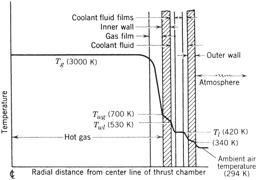
Figure 8–18 Applicable temperature gradients in cooled rocket thrust chamber. The temperatures shown are typical.
The typical steady‐state convection heat transfer relation is shown in Eq. 8–14. For regeneratively cooled thrust chambers, it may be variously expressed as follows (refer to Fig. 8–18):
where q is heat transferred per unit area per unit time, Tg the absolute chamber gas temperature, Tl the absolute coolant liquid temperature, Twl the absolute wall temperature on the liquid side of the wall, Twg the absolute wall temperature on the gas side of the wall, h an overall film coefficient, hg the gas film coefficient, hl the coolant liquid film coefficient, tw the thickness of the chamber wall, and k the conductivity of the wall material. Any consistent set of units may be used in these equations. These simple relations assume that the heat flow is only radial; often, quasi‐one‐dimensional theories also assume that the thermal conductivity and the film coefficients are at average values and not functions of temperature or pressure. A two‐ or three‐dimensional finite element model would be needed to analyze the heat transfer in any axial directions (usually occurring at nozzle throat wall regions where non‐negligible heat is transferred to regions upstream and downstream of it).
Because film coefficients, gas and liquid coolant temperatures, wall thicknesses, and surface areas usually vary with the axial distance L within a combustion chamber (assuming axial heat transfer symmetry), the total heat transfer per unit time Q can be found by integrating the local heat transfer over the entire internal (circular) surface area A of the chamber and the nozzle:
Because both the heat transfer rate per unit area q and the diameter D can often be complicated functions of the thrust chamber length L, the integration is usually carried out by dividing the rocket chamber into finite lengths. Here, L is taken as zero at the injector face. Assuming that q is given by Eqs. 8–13 to 8–19 and remains constant over the length of each element can only give approximate solutions.
The fluid film boundaries established by the combustion products on one side of the wall and by the coolant flow on the other are important quantities controlling the heat transfer across rocket chamber walls. Gas film coefficients establish the amount of the heat transfer rate, and liquid films largely determine the value of the wall temperatures. Film coefficient determinations for use in Eqs. 8–16 and 8–18 may be difficult because of the inherent complex geometries, nonuniform velocity profiles, surface roughness, boundary layer behavior, and combustion oscillations usually present in such systems.
Conventional heat transfer theory is usually presented in terms of several dimensionless parameters (Refs. 8–12, 8–13, and 8–14). Formulations of convection heat transfer in turbulent flows are largely empirical, and one preferred relation for the heating inside circular tubes has been
where hg is the film coefficient, D the diameter of the chamber or of the nozzle, ![]() the calculated average local gas velocity, k the conductivity of the gas, μ the absolute gas viscosity, cp the specific heat of the gas at constant pressure, and ρ the gas density.
the calculated average local gas velocity, k the conductivity of the gas, μ the absolute gas viscosity, cp the specific heat of the gas at constant pressure, and ρ the gas density.
In Eq. 8–20 the quantity hgD/k is known as the Nusselt number, the quantity ![]() as the Reynolds number, and the quantity cpμ/k as the Prandtl number Pr (often tabulated as a property of the fluid). The gas film coefficient hg may also be determined from Eq. 8–21:
as the Reynolds number, and the quantity cpμ/k as the Prandtl number Pr (often tabulated as a property of the fluid). The gas film coefficient hg may also be determined from Eq. 8–21:
where ![]() is the local mass velocity, and the constant 0.023 is dimensionless when compatible units are used. Boundary layer temperature gradients affect the various gas properties in propellant combustion and combustion phenomena are propellant specific. Conventional theoretical approaches, using Eq. 8–20 or 8–21, describe steady‐state flows in relatively long heated circular tubes where “fully developed velocity profiles” can be attained. Heat typically flows into the tube from all sides (360°); however, in thrust chambers the heat flow to the coolant passage comes only from one side of the passage. When chamber lengths are relatively short, equilibrium flow profiles may not form. Actual flows in combustion chamber are highly turbulent containing liquid droplets which are evaporating and often there is no equilibrium. For all these reasons Eqs. 8–20 and 8–21 must be viewed only as good approximations.
is the local mass velocity, and the constant 0.023 is dimensionless when compatible units are used. Boundary layer temperature gradients affect the various gas properties in propellant combustion and combustion phenomena are propellant specific. Conventional theoretical approaches, using Eq. 8–20 or 8–21, describe steady‐state flows in relatively long heated circular tubes where “fully developed velocity profiles” can be attained. Heat typically flows into the tube from all sides (360°); however, in thrust chambers the heat flow to the coolant passage comes only from one side of the passage. When chamber lengths are relatively short, equilibrium flow profiles may not form. Actual flows in combustion chamber are highly turbulent containing liquid droplets which are evaporating and often there is no equilibrium. For all these reasons Eqs. 8–20 and 8–21 must be viewed only as good approximations.
Equations where the coefficients have been validated by actual experimental data tend to be more reliable and they are used in design. Bartz (Ref. 8–14) has surveyed the agreement between theory and experiment and developed semiempirical correction factors incorporated the equation below:

The subscript 0 refers to properties evaluated at the stagnation or chamber combustion temperature; the subscript am refers to properties at the arithmetic mean temperature of the local free‐stream static temperature and the wall temperatures; ρ′ is the free‐stream value of the local gas density. Again, the empirical constant 0.026 is dimensionless when compatible dimensions are used for the other terms. The gas velocity ![]() is the local free‐stream velocity corresponding to the density ρ′. Since the density to the 0.8th power is roughly proportional to the pressure and the gas film coefficient is roughly proportional to the heat flux, so it follows that the heat transfer rate increases approximately linearly with the chamber pressure. These semiempirical heat transfer equations have been further modified and validated for common propellants, limited chamber pressure ranges, and specific injectors and such analysis is often proprietary to specific design organizations.
is the local free‐stream velocity corresponding to the density ρ′. Since the density to the 0.8th power is roughly proportional to the pressure and the gas film coefficient is roughly proportional to the heat flux, so it follows that the heat transfer rate increases approximately linearly with the chamber pressure. These semiempirical heat transfer equations have been further modified and validated for common propellants, limited chamber pressure ranges, and specific injectors and such analysis is often proprietary to specific design organizations.
Temperature drops across inner walls along with the maximum temperature are reduced when the wall is thin and made of a high‐thermal‐conductivity material. Wall thickness is determined from strength considerations and thermal stresses, and some designs have as little as 0.025 in. thickness. Effects of changing the film coefficients are shown in Example 8–1.
Surface roughness has a large outcome on the value of film coefficients and thus on the heat flux. Measurements have shown that the heat flow can be increased by a factor of up to 2 by surface roughness and to higher factors when designing turbulence‐creating obstructions in the cooling channels. Major surface roughness on the gas side will cause the gas to come close to its stagnation temperature locally. However, surface roughness on the liquid coolant side of the wall will enhance turbulence and the absorption of heat by the coolant and reduce wall temperatures.
Figure 8–19 shows heat flow directions, temperature distributions, and locations for maximum wall temperatures in a milled cooling jacket design. This design is represented in (c), the third sketch of Fig. 8–15. The inner wall should be thin, so that the temperature difference across this wall is low and therefore thermal stresses are also low.

Figure 8–19 Results from a two‐dimensional analysis of the heat transfer in two cooling channels of a milled slot‐cooling jacket. The outer wall and the upper parts of the channels are not shown.
Transient Heat Transfer Analysis
An uncooled (high melting point) metal thrust chamber is the simplest type to analyze because there are no chemical or phase changes. Here, thermal equilibrium is not reached. Uncooled walls act essentially as heat sinks continuously absorbing energy from the combustion gases. With the aid of experimental data to determine some typical coefficients, it is possible in some cases to predict the transient heating of uncooled walls.
During propellant combustion, a changing temperature gradient exists across the walls because varying heat is being transferred from the hot gases. The heat being transferred from hot walls to the surrounding atmosphere and to the structure, by conduction in metal parts, can be negligibly small during transient heating. Each wall location experiences a rising temperature as the burning process progresses in time. After the completion of the rocket engine's operation, wall temperatures will tend to equalize.
When axial heat transfer within a metal wall can be neglected, then the heat balance across any wall cross section may be expressed with the one‐dimensional unsteady heat conduction equation (e.g., Ref. 8–12):
Above, T is a function of both the thickness coordinate x and time t. The heat conductivity k may depend on the wall material and its temperature; ρ is the wall material density and ![]() its average specific heat. A typical temperature–time–location history is given in Fig. 8–20. Here, the lower horizontal line at
its average specific heat. A typical temperature–time–location history is given in Fig. 8–20. Here, the lower horizontal line at ![]() denotes the initial wall condition before the rocket engine operates; the various curves show temperature profiles across the wall at successive time intervals after initiation of combustion. The line at
denotes the initial wall condition before the rocket engine operates; the various curves show temperature profiles across the wall at successive time intervals after initiation of combustion. The line at ![]() shows an end temperature of the wall a finite time after cutoff.
shows an end temperature of the wall a finite time after cutoff.

Figure 8–20 Typical temperature distributions through a wall of an uncooled relatively thick metal thrust chamber as a function of heating time t (in seconds).
The heat transferred into any hot wall surface (and distributed within the wall) must not exceed any critical temperature related to the heat‐absorbing capacity of the wall. Equation 8–15 shows that Q/A depends on the hot gas temperature, the wall temperature, and the film coefficients. For calculations, the chamber and nozzle walls may be divided into cylindrical or conical segments as appropriate and each wall segment in turn divided into an arbitrary number of axisymmetric concentric layers, each of a finite thickness. At any given time, the heat conducted by any one wall layer exceeds the heat conducted into the next layer by the amount of heat absorbed (raising the temperature of that particular layer). This iterative approach readily lends itself to two‐ or three‐dimensional computer analyses, resulting in data similar to Fig. 8–20. It is usually sufficient to only determine the heat transfer at the most critical locations.Three‐dimensional analyses must be undertaken when the wall geometry is more complex than purely cylindrical, heat is conducted also in directions other than normal to the axis, temperature variable properties are involved, boundary layers vary with time and location, and more than one material layer is present in the wall.
A number of mathematical simulations of transient heat transfer in ablative materials have been devised, many with limited success. Any such approach must include simulation for the pyrolysis, chemical decomposition, char depth, and outgassing effects on the film coefficient, and requires proper material property data. Most simulations for transient heat transfer require some experimental data.
Steady‐State Transfer to Liquids in Cooling Jacket
The term regenerative cooling applies to rocket engines when one of the propellants is circulated through cooling passages around the thrust chamber prior to being injected and subsequently burned in the chamber. This is represented by a forced convection heat transfer situation. The term regenerative is perhaps not altogether appropriate here as it bears little relation to the meaning given to it in steam‐turbine practice. It is intended to convey the fact that heat absorbed by the coolant propellant is not wasted but augments its initial temperature, raising its internal energy level before injection. This increase in internal energy can be calculated as a correction to the enthalpy of the propellant (see Chapter 5). However, regenerative cooling's overall effect on rocket engine performance is usually very slight. With some propellants the specific impulse can be 1% larger when the propellants are preheated through a temperature differential of 100 to 200°C. In hydrogen‐cooled thrust chambers and in small combustion chambers, where the wall‐surface‐to‐chamber volume ratio is relatively large, the temperature rise in the regenerative coolant will be high, and the resulting increase in specific impulse may exceed 1%.
The liquid film behavior is critical for controlling the wall temperatures in forced convection cooling of rocket devices at high heat fluxes (see Table 8–4 and Refs. 8–12 and 8–16). At least four different film types appear to exist, as can be seen in Fig. 8–21. Here, the dependence of q, the heat transfer rate per unit wall surface, is shown as a function of the difference between the wall temperature on the liquid side Twl and the bulk temperature of the liquid Tl.

Figure 8–21 Regimes in transferring heat from a hot wall to a flowing boiling liquid.
- At low heat fluxes, normal forced convection regions appear to form liquid boundary layers of predictable characteristics. This is indicated by region A–B in Fig. 8–21. Here, the wall temperature is usually below the boiling point of the liquid at the prevailing cooling jacket pressure. In steady‐state heat transfer analysis, the liquid‐film coefficient can be approximated by the following equation (see Refs. 8–11 to 8–14):
where
 is the liquid fluid mass flow rate,
  its average specific heat, A the cross‐sectional cooling jacket flow area, D the equivalent diameter of the coolant passage cross section,1
  the fluid velocity, ρ the coolant density, μ its absolute viscosity, and k its conductivity. Many liquid‐cooled rocket devices operate in this heat transfer regime. Values of the physical properties of several propellants are given in Tables 8–5 and 7–1.
Table 8–5 Heat Transfer Characteristics of Several Liquid Propellants
Boiling Characteristics Nucleate Boiling Characteristics Liquid Coolant Pressure (MPa) Boiling Temp. (K) Critical Temp. (K) Critical Pressure (MPa) Temp. (K) Pressure (MPa) Velocity (m/sec) qmax (MW/m2) Hydrazine 0.101 387 652 14.7 322.2 4.13 10 22.1 0.689 455 20 29.4 3.45 540 405.6 4.13 10 14.2 6.89 588 20 21.2 Kerosene 0.101 490 678 2.0 297.2 0.689 1 2.4 0.689 603 8.5 6.4 1.38 651 297.2 1.38 1 2.3 1.38 651 8.5 6.2 Nitrogen tetroxide 0.101 294 431 10.1 288.9 4.13 20 11.4 0.689 342 322.2 9.3 4.13 394 366.7 6.2 Unsymmetrical dimethyl hydrazine 0.101 336 522 6.06 300 2.07 10 4.9 1.01 400 20 7.2 3.45 489 300 5.52 10 4.7 - When the wall temperature Twl exceeds the boiling point of the liquid by perhaps 10 to 50 K, small vapor bubbles form at the hot wall surface. These small, nuclei‐like bubbles cause local turbulence, break away from the wall, and collapse in the cooler liquid. This phenomenon is known as nucleate boiling. The turbulence induced by the bubbles changes the character of the liquid film and, augmented by the vaporization of some of the propellant, the heat transfer rate is increased without much proportional increase in the temperature drop across the film, as can be seen by the steep slope B – C of the curve in Fig. 8–21. If the pressure of the fluid is raised, then the boiling point is also raised and the nucleate boiling region shifts to the right, to B′– C′. Such boiling permits a substantial increase in the heat transfer beyond that predicted by Eq. 8–24. This phenomenon often occurs locally at the nozzle throat area cooling regions. The maximum feasible heat transfer rate (point C) is indicated as qmax in Fig. 8–21 and Table 8–5 and appears to be a strong function of cooling‐fluid properties, the presence of dissolved gases, pressure, and flow velocity. In Table 8–5 it can be seen that hydrazine is a good heat absorber, but kerosene is poor (low qmax and low critical pressure).
- As the temperature difference is increased further, the rate of bubble formation and the bubble size become so great that the bubbles are unable to escape from the wall rapidly enough. This region (shown as C–D in Fig. 8–21) is characterized by an unstable gas film where it is difficult to obtain reproducible results. When a gas film forms along the hot wall surface, it acts as an insulation layer, causing a decrease in heat flux and, usually, a rapid increase in wall temperature (often resulting in a burnout or melting of the wall material). Cooling flow systems must be designed to avoid this unstable gas film regime.
- As the temperature difference across the film continues to increase, the wall temperatures reach values in which heat transfer by radiation becomes important. Region D–E, however, is not of interest to cooling jacket designers.
Cooling has also been accomplished with fluids above their critical point with coolants such as hydrogen because in this case there is no nucleate boiling and the heat transfer increases with the temperature difference, as shown by the supercritical (dashed) line in Fig. 8–21. Liquid hydrogen is an excellent coolant, has a high specific heat, and leaves no residues. (See Ref. 8–16.)
Chemical changes in liquid coolants can seriously influence the heat transfer. Cracking of hydrocarbon fuels, with an attendant formation of insoluble gases, tends to reduce the maximum heat flux and thus promote failure. Hydrocarbon fuel coolants (methane, jet fuel) can also break down to form solid, sticky carbon deposits inside cooling channels, impeding the heat transfer. Other factors that influence steady‐state coolant heat transfer rates are gas radiation to container walls, bends in the coolant passage, improper welds or manufacture, and flow oscillations caused by turbulence or by combustion unsteadiness. Some propellants, such as hydrazine, can decompose spontaneously and explode inside the cooling passage when they become hot enough.
To achieve a good heat‐absorbing capacity in the coolant, the pressure and the coolant flow velocity are selected so that boiling takes place locally at the hot surface, but the bulk of the coolant does not reach this boiling condition. The total heat rejected by the hot gases to the surface of the hot walls, as given by Eq. 8–14, becomes
where ![]() is the coolant mass flow rate,
is the coolant mass flow rate, ![]() the average specific heat of the liquid, T1 the initial temperature of the coolant as it enters the cooling jacket, and T2 its final temperature; Q is the rate of heat absorption per unit time and A the heat transfer area. The total heat absorbed must be less than the permitted temperature rise in the coolant, namely, value of T2 should remain below the boiling point prevailing at the cooling jacket pressure.
the average specific heat of the liquid, T1 the initial temperature of the coolant as it enters the cooling jacket, and T2 its final temperature; Q is the rate of heat absorption per unit time and A the heat transfer area. The total heat absorbed must be less than the permitted temperature rise in the coolant, namely, value of T2 should remain below the boiling point prevailing at the cooling jacket pressure.
Radiation
Radiation cooling is the electromagnetic energy exchanged by a substance (gas, liquid, or solid) with its environment by the virtue of its higher temperature and at the expense of its internal energy. It is mostly in the infrared but may cover the wavelength range from 10,000 to 0.0001 µm, which includes the visible range of 0.39 to 0.78 µm at the higher temperatures. Radiation heat transfer occurs most efficiently in a vacuum (because there is no absorption by intervening media) and when the surroundings are relatively much cooler.
The amount of heat radiated depends primarily on the temperature of the radiating bodies and on their surface properties. The energy E radiated depends on the fourth power of the absolute temperature T as follows:
The energy E radiated by a body is defined as a function of the emissivity ![]() , which is a dimensionless surface‐condition factor less or equal to one, the Stefan–Boltzmann constant σ (
, which is a dimensionless surface‐condition factor less or equal to one, the Stefan–Boltzmann constant σ (![]() ), the radiating surface area A, the absolute surface temperature T, and a geometric factor f which depends on the geometrical arrangement of adjacent surfaces and their shapes. At low wall temperatures (below 800 K) radiation can usually be neglected.
), the radiating surface area A, the absolute surface temperature T, and a geometric factor f which depends on the geometrical arrangement of adjacent surfaces and their shapes. At low wall temperatures (below 800 K) radiation can usually be neglected.
In rocket propulsion here are primary heat transfer concerns:
- Emission from hot gases to the internal walls of a combustion chamber and its nozzle converging section, or to a solid propellant grain, or to a hybrid propellant grain.
- Emission to the surroundings or to space from external hot hardware surfaces (radiation‐cooled chambers, nozzles, or electrodes in electric thrusters).
- Radiation from hot plume gases (downstream of the nozzle exit). This effect is described in Chapter 20.
In rocket combustion devices at gas temperatures between 1900 and 3900 K or about 3000 to 6600 °F radiation may represent a significant portion of the total heat transfer, between 3 to 40% of the heat transfer to the chamber walls depending on the reaction gas composition, chamber size, geometry, and chamber temperatures. In solid propellant motors radiation heating of grain surfaces may critically affect the burning rate, as discussed in Chapter 12. Radiation from surrounding walls follows essentially the same law as Eq. 8–26. Metal surfaces and formed tubes reflect much radiant energy (low emissivity), whereas ablative materials and solid propellants seem to absorb most of the incident radiation (absorptivity ≈ emissivity). Thus highly reflective surfaces on the inside wall of a combustor tend to reduce radiant absorption and to minimize wall temperature increases. The relative amounts of convective and radiative heat transfer are discussed in Ref. 8–17.
Only few hot reaction gases in rocket combustion chambers are potent radiation sources. Gases with symmetrical molecules, such as hydrogen, oxygen, and nitrogen, have few strong emission bands in wavelength regions of importance in radiant heat transfer. Also, they do not really absorb much radiation and do not contribute significant energies to radiant heat transfer. However, heteropolar gases, such as water vapor, carbon monoxide, carbon dioxide, hydrogen chloride, hydrocarbons, ammonia, oxides of nitrogen, and the alcohols do have strong infrared emission bands (radiation from these molecules is associated with broadened quantum changes in their energy levels of rotation and vibration). In general, for all gases, radiation intensity increases with volume, partial pressure, and fourth power of their absolute temperature. For small thrust chambers at low chamber pressures, gas radiation may usually be neglected.
When the hot flowing gases contain small solid particles or liquid droplets, the heat radiated may increase dramatically, by a factor of 2 to 10. Particulates greatly increase the amounts of radiated energy as explained in Section 20.1. As examples we cite reaction gases from certain organic liquid fuels that contain small solid carbon particles and those of many solid propellants containing fine aluminum powder. When burned to form aluminum oxide, the propellant's heat of combustion and combustion temperature are increased and the specific impulse is raised somewhat. These oxides may exist in liquid droplet form (in the chamber) or solid particles (in the nozzle diverging section), depending on the local gas temperature. Furthermore, with wall impacts these particulates cause additional increases in heat transfer, mainly at the nozzle throat walls and immediately upstream of the nozzle throat region. Wall impacts may also cause unwanted erosion and/or abrasion at the walls.
8.6 STARTING AND IGNITION
Thrust chamber starting has to be controlled to achieve timely and even propellant ignition so that the flow and the thrust built up smoothly and quickly to their rated value (see Refs. 6–1, 8–18 and 8–19). Note that any initial propellant flow is always less than full flow and that any starting mixture ratio is usually different from the operating mixture ratio. A low initial flow prevents strong water hammer, gives a lower initial heat release, and for nonhypergolic propellants prevents unwanted or excessive accumulations of unignited liquid propellants in the chamber.
Because during starting injection velocities are low, the initial vaporization, atomization, and mixing of propellants in a cold combustion chamber is often incomplete and there can be localized regions of lean and rich mixtures. With cryogenic propellants the initial chamber temperature can be below ambient. The optimum starting mixture is therefore only one of a range of mixture ratios, all of which must readily ignite. Mixture ratios near stoichiometric have the highest heat release per unit propellant mass and therefore bring the chamber and its gases up to equilibrium faster than with other mixtures. Operating mixture ratios, however, are nearly always fuel rich usually selected for optimum specific impulse. One method for modeling cryogenic propellant ignition of is given in Ref. 8–18.
Ideally, time delays for starting any thrust chamber should consist of the following time increments:
- Time needed to fully open propellant valves (typically between 0.002 to over 1.00 sec), depending on valve type and size, and upstream pressure).
- Time needed to fill liquid passage volumes (piping, manifolds, internal injector feed holes, and cavities) between the valve seat and the injector face.
- Time for forming discrete streams or sprays of liquid propellant, for initial atomization into small droplets, and for mixing these droplets. With cryogenic propellants initial flows are usually gaseous so this time would differ.
- With current hypergolic propellant combinations at ambient initial temperatures, combustion starts within a few milliseconds after the fuel (droplet or vapor) comes into contact with the oxidizer (droplet or vapor). This delay lengthens at lower ambient temperatures and at off‐design mixtures ratios.
- For nonhypergolic propellant combinations, an igniter system must bring the mixed propellant flow to its ignition temperature before combustion can start. This igniter is usually started before any propellant is admitted to the chamber, before propellant valves are opened. The igniter operating time before propellant comes in contact with it can be one or more seconds in larger thrust chambers (if properly sensed, when an igniter fails to operate engine controls can be made to block the opening of propellant valves).
- Time needed for droplets to vaporize and ignite (laboratory tests show this can be as short as 0.02 to 0.05 sec, depending on the propellants and the existing heat transfer).
- Once ignition is achieved at one particular location in the chamber, there is a finite flame spread time plus a time to heat all the mixed propellant that is entering into the chamber, vaporizing it, and raising it to ignition temperature.
- Time needed to raise the chamber pressure and temperature to the condition where combustion is self‐sustaining. Only then has the system been raised to its full operating state.
There are overlaps in these delays because several of them may occur simultaneously. Large injectors and/or large‐diameter chambers cause longer delays. Small thrusters can usually be started relatively quickly, in a few milliseconds, while larger units require one second and sometimes as much as 5 sec to reach full thrust.
In the starting of thrust chambers, it is difficult to exactly synchronize the fuel and oxidizer feed systems so that propellants reach the chamber simultaneously from all injection holes or spray elements. Frequently, more reliable ignitions are assured when one of the propellants is intentionally made to reach the chamber first. For example, for fuel‐rich starting mixtures the fuel is admitted first. Reference 8–19 describes the control of such propellant lead.
Other factors influencing flow starting, propellant lead or lag, and some of the delays mentioned above relate to the pressures supplied to the liquid injectors (e.g., regulated pressure), the temperature of the propellant (some can be stored close to their vapor point), and to the amount of insoluble gas (air bubbles) mixed with the initial quantity of propellants.
Propellant valves (and flow passages between these valves and the injector face) are often so designed and controlled that they operate in a definite sequence, thereby assuring an intentional lead of one of the propellants and a controlled buildup of flow and mixture ratio. Often these valves are only partially opened because it is easier to ignite a small flow thus avoiding accumulation of hazardous unburned propellant mixtures in the chamber. Once combustion is established, valves are fully opened and full flows reach the thrust chamber assembly. This initial reduced flow burning period is called the preliminary stage. Section 11.4 describes the starting controls.
Full flows in larger thrust chambers are not initiated with non‐self‐igniting propellants until the controller received a signal of successful ignition. The verification of ignition or initial burning is often built into engine controls using image detectors (photocells), heat detectors (pyrometers), fusible wire links, or by sensing pressure rises. If starting controls are not designed properly, unburnt propellant may accumulate in the chamber, which may then explode upon ignition, possibly causing severe damage to the rocket engine. Starting controls and engine calibrations are discussed in Sections 11.4 and 11.5.
Nonspontaneously ignitable propellants are activated by the absorption of energy prior to combustion initiation. This energy is supplied by an ignition system as described below. Once ignition has begun, the flame becomes self‐supporting. The igniter has to be located near the injector in such a manner that a satisfactory starting mixture at low initial flows is present at the time of igniter activation, yet it should not hinder or obstruct the steady‐state combustion process. At least five different types of successful propellant ignition systems have been used:
Spark plug ignition has been used successfully on liquid oxygen–gasoline and on oxygen–hydrogen thrust chambers, particularly for multiple starts during flight. The spark plug is often built into the injector. The RS‐25 (Aerojet Rocketdyne's designator for the SSME) uses a redundant augmented spark igniter in the main combustion chamber and preburners.
Ignition by electrically heated wires has been accomplished but at times has proven to be less reliable than spark ignition with liquid propellants.
Pyrotechnic ignition uses solid propellant squibs or grains of a few seconds' burning duration. This solid propellant “charge” is electrically ignited and burns with a hot flame within the combustion chamber. Almost all solid propellant rockets and many liquid rocket chambers are ignited in this fashion. The igniter container may be designed to fit directly onto the injector or the chamber (as in Fig. 8–1), or may be held in the chamber from outside through the nozzle. The latter ignition method can only be used once; thereafter, its “charge” has to be replaced.
Ignition has been achieved in a precombustion chamber also called premix chamber; see Fig. 8–3; it is a small chamber built next to the main combustion chamber and connected through an orifice; this is similar to the precombustion chamber used in some automobile engines. A small amount of fuel and oxidizer is injected into the precombustion chamber and ignited. The burning mixture enters the main combustion chamber in a torchlike fashion and ignites the larger main‐propellant flow as it is being been injected into the main chamber. This ignition procedure permits the repeated starting of thrust chambers and has proven successful with the liquid oxygen–gasoline and oxygen–hydrogen thrust chambers.
Auxiliary fluid ignition is a method whereby some hypergolic liquid or gas, in addition to the regular fuel and oxidizer, is injected into the combustion chamber for a short period during the starting operation. This fluid produces spontaneous combustion with either the fuel or the oxidizer. The combustion of nitric acid and some organic fuels can, for instance, be initiated by the introduction of a small quantity of hydrazine or aniline at the beginning of rocket operation. Liquids that ignite with air (e.g., zinc diethyl or triethyl aluminum), when preloaded in the fuel piping, can also accomplish hypergolic ignition. A mixture of triethyl aluminum and triethyl borane has been successfully used for liquid oxygen and RP‐1 (kerosene) ignition in several U.S. and Russian rocket engines. Flow diagrams for two Russian rocket engines, the RD 191 in Fig. 6–13 and the RD 170 in Fig. 11–2, show cylindrical containers (start fuel tanks or ampoules) with a hypergolic liquid for each of the high‐pressure fuel supply lines; this liquid is pushed out (by the initial fuel) into the thrust chambers and into the preburners to start ignition.
Vehicles with multiple engines or thrust chambers are required to start two or more together, although it is often difficult to get precisely simultaneous starts. Usually, the passage or manifold volumes of each thrust chamber and their respective values are designed to be the same. Careful control of temperature of the initial propellant fed to each thrust chamber and of lead time of the first quantity of propellants entering into the chambers is needed. This is required, for example, when two thrusters are used to apply roll torques to a vehicle. It is also one reason why large space launch vehicles are not released from their launch facility until there is assurance that all thrust chambers are started and operating.
During storage or between ground tests, nozzle throat plugs or alternatively round nozzle exit covers are routinely used. These prevent dust, moisture, and small creatures (e.g., ants, mice) from entering the chamber and/or injectors. These units are usually removed manually just before thrust chamber operation or may be ejected automatically by the rising chamber pressure during starts.
8.7 USEFUL LIFE OF THRUST CHAMBERS
The useable life of a thrust chamber is given by the number of starts or full‐thrust operations that can be performed safely, without undue risk of failure. There are two relevant categories: First, for flight missions where the thrust chamber can be recovered between flights, an opportunity exists to inspect and if needed maintain and repair before the next flight. A typical of large recoverable thrust chamber was the Space Shuttle Main Engine (SSME, Aerojet Rocketdyne) and, presently, the Merlin engine for the Falcon 9 vehicle (SpaceX). NASA wanted the SSMEs designed for 100 flights but they only flew between 5 and 20 times because of factors not related to thrust chamber lifetimes.
There are several life‐limiting sources in recoverable units. At their inner walls, thrust chambers deteriorate by gradual oxidation from the combustion gases (O, O2, H2O, etc.), though these species may only be present in relatively small amounts, and from crack formations usually near the throat. Moreover, as inner walls of cooling jackets are heated, they expand and grow slightly all directions. However, because of their construction, these inner walls are restricted from freely expanding by the cooler outer walls (see Figs. 8–9 and 8–15). Having a lower yield stress at higher temperatures, an inner wall will yield in compression causing slight shrinking on the hotter side. After shutdown, an inner wall will also (slightly) shrink as it cools but will not get back to exactly the original size, thus having to yield under tension. These effects cause the formation of small surface cracks on inside inner walls. With each new start and shutdown, such cracks deepen and become more numerous. Ultimately, the damaged inner walls can no longer tolerate the chamber pressure loads and the thrust chamber will fail. Most thrust chambers have relatively thin inner walls of high conductivity materials to decrease thermal stresses and thus achieve longer lives.
The second category relates to the small‐pulse multiple thrusters typically found in the reaction control system of nonrecoverable but long‐duration space missions, such as long‐term orbit maintenance or deep space flights. Here, the cumulative number of starts or pulses could be between 1000 and 50,000 for multiyear mission durations. During development, one or more thrusters are usually endurance tested for several hundred thousand cycles in a vacuum chamber. The useful life of small thrusters is limited by the fatigue failure of valves and other structures in the reaction control system, and also by oxidation and/or erosion of walls exposed to propellant gases. Many types of small thrusters have been life‐tested, including units with radiant cooling and with ablative inner liners in both their monopropellant and bipropellant versions (Refs. 8–8 and 8–20). With monopropellant small thrusters, thruster life is often limited by the attrition and/or poisoning of the catalyst (see Section 8.3).
8.8 RANDOM VARIABLE THRUST
Only some applications require randomly variable engine thrust, for example, rocket descents to another planet or moon or of the upper stage of anti‐ballistic missiles. One advantage of liquid propellant rocket engines is that they can be designed to be throttled (i.e., to randomly vary their thrust) over wide ranges during flight. Several approaches exist to achieve throttling (all involve the thrust chamber and therefore this section has been placed here). One early scheme was to use multiple engines or multiple thrust chambers on the same engine and then stopping operation of one or more of them. The now historic Reaction Motors 6,000C‐4 engine had four thrust chambers and they could be turned on or off individually producing step changes in thrust.
Today we distinguish between two modes of operation, though both depend on reducing propellant flow. The first is moderate throttling, typically over a thrust range of factors of two or three, which can usually be accomplished with modified propellant valves without significant design changes to the engine. In one application, the thrust is throttled during the ascent of a booster vehicle in order to prevent excessive aerodynamic pressure or heating of the vehicle. The other mode, often called deep throttling, varies the thrust by factors between 6 and 30 for specific engines. It applies, for example, to a planetary landing rocket engine with controlled deceleration. To achieve this deep throttling, engines require some special features, some of which are mentioned below.
Thrust is mostly proportional to propellant mass flow (Eq. 2–13) and therefore reducing propellant flow will reduce thrust. Moderate throttling can be achieved by partially closing the main fuel and oxidizer valves (matching flow characteristics) simultaneously or by slowing down the rotary speed of the turbopumps (by reducing the gas flow to their turbine) with hydraulically matched fuel and oxidizer pumps. At the lower flows, the pressure drop across the injector and the injection velocity will diminish, the atomization and mixing of the propellants will be somewhat less efficient and the combustion will be less complete, and chamber pressures will be reduced. These decrease the specific impulse at the lower thrust levels of perhaps 1.5 to 9%, depending on specific engine design. Such method for varying thrust is used in a number of booster engines for space launch vehicles.
With the deeper throttling, oxidizer and fuel flows tend to oscillate and will usually no longer remain at the original mixture ratio, the propellant injection streams or sprays and their impingement locations will wander, and their flow is likely to become erratic. To prevent these, engines need to have some special features like those found in the engine used in the first lunar landing rocket—this engine, developed by the predecessor of Northrop Grumman, flew in the late 1960s and 1970s and was throttled by a factor of up to 10:1; each propellant flow control valve included a cavitating venturi with a movable tapered pintle that allowed flow area variations in the venturi throat of the thrust chamber valve; this assured predetermined steady reduced flows of propellants at all thrust levels, and maintained a constant mixture ratio; furthermore, propellant injection was accomplished through a pintle injector with two annular slots and the width of these slots could be reduced by an actuator built into the injector. A lower right sketch in Fig. 8–3 shows this feature. It allows for high injection velocities of liquid propellants, giving good atomization and adequate combustion with relatively small losses in performance at low thrusts. The highest thrust variation (327 to 1.0) has been obtained with the sustainer engines of the Lance surface‐to‐surface missile. It had two concentric thrust chambers—a small one inside a larger one. Its engine, developed by Rocketdyne (today Aerojet Rocketdyne), first flew in the late 1960s and was deployed in the 1970s until 1990. The specific impulse at low thrust was poor (more than 15% loss). See Ref. 8–1.
Another approach to achieve variable thrust is to vary the nozzle throat area (see Eq. 3–31). This scheme requires a movable tapered pintle in the main nozzle throat area. The pintle has to be made of heat‐resistant materials or has to be regeneratively cooled, and its position is usually hydraulically controlled. This will allow the unit to maintain essentially constant chamber pressure at all thrust levels. Several experimental liquid propellant engines and solid propellant motors with random variable nozzle throat areas have been built and tested. To the best of the authors' knowledge, none have flown.
For pulsed, small reaction control thrusters the average thrust can be noticeably reduced by changing the pulsing mode. This is accomplished by controlling the number of cycles or pulses (each having one short fixed‐duration thrust pulse plus a short fixed‐duration zero‐thrust pause), by modulating the duration of individual pulses (with short pauses between pulses), or alternatively by lengthening the pause between pulses.
8.9 SAMPLE THRUST CHAMBER DESIGN ANALYSIS
In this example we show how the preliminary design of a thrust chamber is strongly influenced by overall vehicle system requirements and mission parameters; it illustrates vehicle design procedures and factors that are considered in the selection of some key thrust chamber parameters., In order to arrive at key design parameters, each engine goes through a series of rationalizations and requirements. This is outlined in the design section of Chapter 11 and in the discussion of the selection of propulsion systems in Chapter 19. In this example, we describe one of several ways of deriving thrust chamber parameters from both vehicle and engine requirements. Overall system requirements relate to the mission, its purpose, environment, trajectories, reusability, reliability, and to restraints such as allowable engine mass, or maximum dimensional envelope. Even though we list only some relevant requirements, this example shows how theory needs to be blended with experience to arrive at initial design choices; these will differ when done by different design teams.
SYMBOLS
| A | area, m2 (ft2) |
| cp | gas specific heat at constant pressure, J/kg‐K (Btu/lbm°R) |
| average liquid or solid specific heat, J/kg‐K (Btu/lbm°R) | |
| Cd | discharge coefficient |
| CF | thrust coefficient |
| D | diameter, m (ft) |
| E | modulus of elasticity, N/m2 (lbf/in.2), or radiation energy, W |
| f | friction loss coefficient, or geometric factor in radiation |
| g0 | sea‐level acceleration of gravity, 9.806 m/sec2 (32.17 ft/sec2) |
| h | convective film coefficient, W/(m2‐K); (Btu/(ft2‐°R) |
| Is | specific impulse, sec |
| κ | specific heat ratio |
| L | length, m (ft) |
| L* | characteristic chamber length, m (ft) |
| m | mass, kg |
| mass flow rate, kg/sec (lb/sec) | |
| p | pressure, N/m2 or Pa (lbf/in.2) |
| Pr | Prandtl number (cpμ/k) |
| q | heat transfer rate or heat flow per unit area, J/m2‐sec (Btu/ft2‐sec) |
| Q | volume flow rate, m3/sec (ft3/sec), or heat flow rate, J/sec |
| R | Reynolds number Dvρ/μ |
| r | flow mixture ratio (oxidizer to fuel); or radius, m (ft) |
| s | stress N/m2 (lbf/in.2) |
| t | time, sec, or thickness, m (ft) |
| ts | stay time, sec |
| tw | wall thickness, m (in.) |
| T | absolute temperature, K (°R) |
| Δu | flight velocity increment m/sec (ft/sec) |
| velocity, m/sec (ft/sec) | |
| specific volume, m3/kg (ft3/lb) | |
| Vc | combustion chamber volume (volume up to throat), m3(ft3) |
| x, y | coordinates of a parabola with constant a |
Greek Letters
| γo | angle between chamber axis and oxidizer stream |
| γf | angle between chamber axis and fuel stream |
| δ | angle between chamber axis and the resultant stream |
| ε | nozzle exit area ratio (ε = A2/At) |
| emissivity of radiating surface, dimensionless | |
| θ | angle |
| k | thermal conductivity, J/(m2‐sec‐K)/m (Btu/in.2‐sec2‐°R/in.) |
| λ | coefficient of thermal expansion, m/m‐K (in./in.‐°R) |
| μ | absolute gas viscosity, kg/(m‐sec) or lbf/ft2‐sec |
| ν | Poisson ratio |
| ρ | density, kg/m3(lbf/ft3) |
| σ | Stefan–Boltzmann constant ( |
Subscripts
| am | arithmetic mean |
| c | Chamber |
| f | fuel or final condition |
| g | Gas |
| gg | gas generator |
| inj | Injector |
| l | Liquid |
| o | Oxidizer |
| t | Throat |
| tc | thrust chamber |
| w | Wall |
| wg | wall on side of gas |
| wl | wall on side of liquid |
| 0 | initial condition |
| 1 | inlet or chamber condition |
| 2 | nozzle exit condition |
| 3 | atmosphere or ambient condition |
PROBLEMS
- How much total heat per second can be absorbed in a thrust chamber with an inside wall surface area of 0.200 m2 if the coolant is liquid hydrogen and the coolant temperature does not exceed 145 K in the jacket? Coolant flows at 2 kg/sec. What is the average heat transfer rate per second per unit area? Use the data from Table 7–1 and the following:
Heat of vaporization near boiling point 446 kJ/kg Thermal conductivity (gas at 21 K) 0.013 W/m‐K (gas at 194.75 K) 0.128 W/m‐K (gas at 273.15 K) 0.165 W/m‐K - During a static test a certain steel thrust chamber is cooled by water in its cooling jacket. The following data are given for the temperature range and pressure of the coolant:
Determine (a) the film coefficient of the coolant; (b) the wall temperature on the coolant side; (c) the wall temperature on the gas side.Average water temperature 100 °F Thermal conductivity of water 
Gas temperature 4500 °F Specific gravity of water 1.00 Viscosity of water 
Specific heat of water 1.3 Btu/lb‐°F Cooling passage dimensions  in.
in.Water flow through passage 0.585 lb/sec Thickness of inner wall  in.
in.Heat absorbed 1.3 Btu/in.2‐sec Thermal conductivity of wall material 26 Btu/hr‐ft2‐°F/ft - In Problem 2 (above) determine the water flow required to decrease the wall temperature on the gas side by 100 °F. What is the percentage increase in coolant velocity? Assume that the various properties of the water and the average water temperature do not change.
- Determine the absolute and relative reduction in wall temperatures and heat transfer caused by applying insulation in a liquid‐cooled rocket chamber with the following data:
A 0.2‐mm‐thick layer of insulating paint is applied on the gas side; the paint consists mostly of magnesia particles. The average conductivity of this magnesia paint is 2.59W/m2‐K/m over the temperature range. The stainless steel has an average thermal conductivity of 140 Btu/hr.−ft2‐°F/in and a specific gravity of 7.98Tube wall thickness 0.381 mm Gas temperature 2760 K Gas‐side wall temperature 1260 K Heat transfer rate 15 MW/m2‐sec Liquid‐film coefficient 23 kW/m2‐K Wall material Stainless steel AISI type 302 - A small thruster has the following characteristics:
Determine the number of oxidizer and fuel injection holes and their angles. Make a sketch to show the symmetric hole pattern and the feed passages in the injector. To protect the wall, the outermost holes should all be fuel holes.Propellants Nitrogen tetroxide and monomethyl hydrazine Injection individual hole size 0.063 in. for oxidizer and 0.030 in. for fuel Injection hole pattern Unlike impinging doublet Thrust chamber type Ablative liner with a carbon–carbon nozzle throat insert Specific gravities 1.446 for oxidizer and 0.876 for fuel Impingement point 0.25 in. from injector face Direction of jet momentum Parallel to chamber axis after impingement 


- A large, uncooled, uninsulated, low‐carbon‐steel thrust chamber burned out at the throat region during testing. The wall (0.375 in. thick) had melted and there were several holes. The test engineer said that he estimated the heat transfer to have been about 15 Btu/in.2. The thrust chamber was repaired, and assume that you are responsible for the next test. Someone suggested that a series of water hoses be hooked up to spray plenty of water on the outside of the nozzle wall at the throat region during the next test to prolong the firing duration. The steel's melting point is estimated to be 2550 °F. Because of the likely local variation in mixture ratio and possibly imperfect impingement, you anticipate some local gas regions that are oxidizer rich and could start the rapid oxidation of the steel. You therefore decide that 2150 °F should be the maximum allowable inner wall temperature. Besides knowing the steel weight density (0.284 lbf/in.3), you have the following data for steel for the temperature range from ambient to 2150 °F: the specific heat is 0.143 Btu/lbm‐°F and the thermal conductivity is 260 Btu/hr‐ft2‐°F/in. Determine the approximate time for running the next test (without burnout) both with and without the water sprays. Justify any assumptions you make. If the water spray seems to be adequate (getting at least 10% more burning time), make sketches with notes on how the mechanic should arrange for this water flow during testing so it will be most effective.
- The following conditions are given for a double‐walled cooling jacket of a rocket thrust chamber assembly:
Assume other parameters, if needed. Compute the outside diameters and the thickness of the inner and outer walls at the chamber, at the throat, and at the nozzle exit.Rated chamber pressure 210 psi Rated jacket pressure 290 psi Chamber diameter 16.5 in. Nozzle throat diameter 5.0 in. Nozzle throat gas pressure 112 psi Average inner wall temperature at throat region 1100 °F Average inner wall temperature at chamber region 800 °F Cooling passage height at chamber and nozzle exit 0.375 in. Cooling passage height at nozzle throat 0.250 in. Nozzle exit gas pressure 14.7 psi. Nozzle exit diameter 10 in. Wall material 1020 carbon steel Inner wall thickness 0.08 in. Safety factor on yield strength 2.5 Cooling fluid RP‐1 Average thermal conductivity of steel 250 Btu/hr‐ft2‐°F/in. - Determine the hole sizes and the angle setting for a multiple‐hole, doublet impinging stream injector that uses alcohol and liquid oxygen as propellants. The resultant momentum should be axial, and the angle between the oxygen and fuel jets (γo + γf) should be 60°. Assume the following:
Answer: 0.0197 in.; 0.0214 in.; 32.3°; 27.7°.(Cd)o 0.87 Chamber pressure 300 psi (Cd)f 0.91 Fuel pressure 400 psi ρo 71 lb/ft3 Oxygen pressure 380 psi ρf 51 lb/ft3 Number of jet pairs 4 r 1.20 Thrust 250 lbf Actual specific impulse 218 sec - Table 11–3 shows that the RD‐120 rocket engine can operate down to 85% of full thrust and at a mixture ratio variation of ± 10.0%. In a particular static test the average thrust was held at 96% of nominal and the average mixture ratio was 2.0% fuel rich. Assume a 1.0% residual propellant, but neglect other propellant budget allowances. What percentage of the fuel and oxidizer that have been loaded will remain unused at thrust termination? If we want to correct the mixture ratio in the last 20.0% of the test duration and use up all the available propellant, what would be the mixture ratio and propellant flows for this last period?
- Make a simple cross‐section sketch approximately to scale of the thrust chamber that was analyzed in Section 8.9. The various dimensions should be close, but need not be accurate. Include or make separate detailed‐section sketches of the cooling jacket and the injector. Also compile a table of all the key characteristics, similar to Table 8–1, but include gas generator flows and key materials. Make estimates or assumptions for any key data that is not mentioned in Section 8.9.
REFERENCES
- 8–1. G. P. Sutton, History of Liquid Propellant Rocket Engines, AIAA, Reston, VA, 2006.
- 8–2. M. M. Mielke et al., “Applications of Ultrafast Lasers in Microfabrication,” Journal of Laser Micro/Nanoengineering, Vol. 28, No.2, Aug. 2013, pp. 115–123. doi: 102961/jlmn2013.02.0001.
- 8–3. V. Yang, M. Habiballah, J. Hulka, and M. Popp, (Eds.), Liquid Rocket Thrust Chambers: Aspects of Modeling, Analysis, and Design, Progress in Astronautics and Aeronautics (Series), Vol. 200, AIAA, Reston, VA, 2004.
- 8–4. K. W. Brinckman et al., “Impinging Fuel Injector Atomization and Combustion Modelling,” AIAA Paper 2015‐3763, Orlando, FL, 2015.
- 8–5 R. D. McKown, “Brazing the SSME,” Threshold, an Engineering Journal of Power Technology, No. 1, Rocketdyne Division of Rockwell International (now Aerojet‐ Rocketdyne.), Canoga Park, CA, Mar. 1987, pp. 8–13.
- 8–6. R. A. Ellis, J. C. Lee, F. M. Payne, M. Lacoste, A. Lacombe, and P. Joyes, “Testing of the RL 10B‐2 Carbon‐Carbon Nozzle Extension,” AIAA Conference Paper 98‐3363, Jul. 1998.
- 8–7. M. Niino, A. Kumakawa, T. Hirano, K. Sumiyashi, and R. Watanabe, “Life Prediction of CIP Formed Thrust Chambers,” Acta Astronautica, Vol. 13, Nos. 6–7, 1986, pp. 363–369 (fatigue life prediction).
- 8–8. J. S. Porowski, W. J. O'Donnell, M. L. Badlani, B. Kasraie, and H. J. Kasper, “Simplified Design and Life Predictions of Rocket Thrust Chambers,” Journal of Spacecraft and Rockets, Vol. 22, No. 2, Mar.–Apr. 1985, pp. 181–187.
- 8–9. A. J. Fortini and R. H. Tuffias, “Advanced Materials for Chemical Propulsion: Oxide‐Iridium/Rhenium Combustion Chambers,” AIAA Paper 99‐2894, Jun. 1999.
- 8–10. U. Gotzig et al., “Development and Test of a 3D Printed Hydrogen Peroxide Fight Control Thruster,” AIAA Paper 2015‐4161, Orlando FL, 2015; H. Kenjon, “TRUST: 3‐D Manufacturing's Holy Grail,” Aerospace America, Vol. 53, No. 7, Jul.–Aug. 2015, pp. 42–45.
- 8–11. Personal information from J. D. Haynes, Additive Manufacturing Program Manager, Aerojet Rocketdyne, 2015.
- 8–12. F. P. Incropera, D. P. DeWitt, T. L. Bergman, and A. S. Lavine, Introduction to Heat Transfer, 5th ed., John Wiley & Sons, Hoboken, NJ, 2006.
- 8–13. A. A. Samarskii and P. N. Vabishchevich, Computational Heat Transfer, Vol. 1. Mathematical Modeling, and Vol. 2. The Finite Difference Methodology. John Wiley & Sons, New York, 1995, 1996.
- 8–14. R. W. Lewis, Perumal Nithiarasu, and Kankanhalli Seetharamu, Fundamentals of the Finite Element Method for Heat and Fluid Flow. John Wiley & Sons, Hoboken, NJ, 2004.
- 8–15. D. R. Bartz, “Survey of Relationships between Theory and Experiment for Convective Heat Transfer in Rocket Combustion Gases,” in Advances in Rocket Propulsion, S. S. Penner (Ed.), AGARD, Technivision Services, Manchester, England, 1968.
- 8–16. J. M. Fowler and C. F. Warner, “Measurements of the Heat‐Transfer Coefficients for Hydrogen Flowing in a Heated Tube,” American Rocket Society Journal, Vol. 30, No. 3, March 1960, pp. 266–267.
- 8–17. B. Betti et al., “Convective and Radiative Contributions to Wall Heat Transfer in Liquid Rocket Engine Thrust Chambers,” AIAA Paper 2015‐3757, Orlando, FL, 2015.
- 8–18. P. A. Baudart, V. Duthoit, T. Delaporte, and E. Znaty, “Numerical Modeling of the HM 7 B Main Chamber Ignition,” AIAA Paper 89‐2397, 1989.
- 8–19. A. R. Casillas, J. Eninger, G. Josephs, J. Kenney, and M. Trinidad, “Control of Propellant Lead/Lag to the LEA in the AXAF Propulsion System,” AIAA Paper 98‐3204 Jul. 1998.
- 8–20. C. Gafto and B. Nakazro, “Life Test Results of a MONARCH5 1 lbf Monopropellant Thruster with the Haraeus Catalyst,” AIAA Paper 2014‐3795, 2014.