
CHAPTER 9
LIQUID PROPELLANT COMBUSTION AND ITS STABILITY
In this chapter, the complexities of combustion chamber phenomena found in liquid bipropellant thrust chambers are treated. We describe combustion behavior and its analysis in general terms, together with several types of combustion instability with their resulting undesirable effects, and discuss semiempirical remedies on how to avoid these effects. An objective here is to operate at very high combustion efficiencies while preventing any occurrence of disruptive or destructive combustion instabilities. Thrust chambers need to operate with stable combustion over a wide range of operating conditions. Further treatment of these subjects can be found in Refs. 9–1 to 9–7.
Liquid propellant combustion is very efficient in well‐designed thrust chambers. Combustion efficiencies of between 95 to 99.5% are typical, in contrast to turbojets or ordinary furnaces which may range from 50 to 97%. Such high efficiencies stem from the very fast reaction rates at high combustion temperatures resulting from the thorough mixing of fuel and oxidizer (from proper injection flow distributions, uniform atomization, and turbulent gas diffusion). Losses arise from nonuniform mixture ratios resulting in incomplete burning or inadequate mixing. Combustion efficiencies can be well below 95% in very small bipropellant thrust chambers or small gas generators because their injectors lack sufficient injection orifices or elements for proper mixing.
9.1 COMBUSTION PROCESS
For understanding combustion processes, it is helpful to divide the combustion chamber into a series of discrete zones as shown in Fig. 9–1. The configuration depicted has a flat injector face with many small injection orifices that introduce both fuel and oxidizer liquids into the combustion chamber and this results in many discrete liquid propellant streams, or thin sprays or sheets. The relative thickness, behavior, and transition of each discrete zone in the axial direction is strongly influenced by specific propellant combination, operating conditions (pressure, mixture ratio, etc.), and by injector design and chamber geometry. The boundaries between the zones shown in Fig. 9–1 are really neither flat nor steady surfaces. They can be undulating or movable irregular boundaries with local changes in velocity, temporary bulges, locally intense radiation emissions, and/or variable temperatures. Table 9–1 shows all major interacting physical and chemical processes that may occur in the chamber. This table is a modification of tables and data in Refs. 9–1, 9–2, and 9–7.

Figure 9–1 Division of combustion chamber into zones for analysis.
Modified from Y. M. Timnat, Advanced Chemical Rocket Propulsion, Academic Press, New York, 1987.
Table 9–1 Physical and Chemical Processes in the Combustion of Liquid Propellants
| Injection | Atomization | Vaporization |
|
Liquid jets or sprays enter chamber at relatively low velocities Sometimes gaseous propellant is injected (e.g., hydrogen) Partial evaporation of liquids Interaction of jets or sprays with high‐pressure hot gas |
Impingement and breakup of jets or sheets Formation of liquid fans or spray cones Formation of droplets Secondary breakup of droplets Liquid mixing and some liquid–liquid chemical reactions Oscillations of jets or fans or spray liquid sheets as they become unstable during breakup Vaporization begins and some vapor reactions occur |
Droplet gasification and gas diffusion Further heat release from local chemical reactions Relatively low gas velocities and some cross flow Heat absorbed in droplets by radiation, convection, and conduction; some blowback of turbulent gases from the hot reaction zone into injector zone Acceleration to higher velocities Vaporization rate influenced by turbulence, pressure or temperature oscillations and acoustic waves |
| Mixing and Reaction | Expansion in Chamber | |
|
Turbulent mixing (three‐dimensional) Multiple chemical reactions and major heat releases Interactions of turbulence with droplets and chemical reactions Temperature rise reduces densities and increases volume flow Local mixture ratios, reaction rates, or velocities are not uniform across chamber and vary rapidly with time Some tangential and radial flows, much of it near the injector |
Chemical kinetics causes attainment of final combustion temperature and final equilibrium reaction gas composition Acceleration to high chamber velocities Gas dynamics displays turbulence and increasing axial gas velocities Formation of a boundary layer Streamlined high‐velocity axial flow with very little cross flow Flow toward nozzle Heat transfer to walls |
|
Combustion behavior is highly propellant injection dependent. With a hypergolic propellant combination there is an initial chemical reaction in the liquid phase as droplets of fuel impinge on droplets of oxidizer. Experiments show that such contacts can create local mini‐explosions with enough energy release to suddenly vaporize thin layers of fuel and oxidizer locally at the droplet's contact face—there immediately follows a vapor chemical reaction and droplets blow‐apart and breakup. Small local explosions have been documented (Refs. 9–8 and 9–9). In contrast, when a cryogenic fuel like hydrogen comes from cooling the thrust chamber, the injected hydrogen is gaseous and relatively warm (60 to 240 K); here, there are no hydrogen droplets to evaporate.
Combustion processes are typically analyzed as steady flow, but in reality this is not truly so. When observing any one location within the chamber, one finds turbulent flows with local fluctuations in pressure, flow, temperature, density, mixture ratio, and/or radiant emission. Some of the processes listed in the table occur sequentially, while others may occur simultaneously. Not all listed processes happen with each propellant. Three‐dimensional turbulence consistently forms in all parts of the combustion chamber and in the nozzle. Most combustion also generates a great deal of noise.
Injection/Atomization Zone
Typically, two different liquids are being injected, either storable bipropellants or liquid oxygen–hydrocarbon combinations. These are injected through orifices or slots at speeds usually between 7 and 60 m/sec or about 20 to 200 ft/sec. Injector design has a profound influence on combustion behavior and some seemingly minor design changes may have major effects on instabilities. Orifice pattern, sizes, number, distribution, and types influence combustion behavior, as do pressure drops, manifold geometries, and/or surface roughness at the injection orifice walls. Individual jets, streams, and/or liquid sheets break up into droplets by mutual impingement (or with a surface), by impingement of conical spray sheets, by the intrinsic instability of liquid jets or sprays, and/or by their interaction with gases at different velocities and temperatures. In the first zone of Fig. 9–1, injected liquids atomize, yielding large numbers of small droplets (see Refs. 9–1, 9–6 to 9–9). Heat is transferred to these droplets by radiation from the very hot rapid‐combustion zone and by convection from moderately hot gases within the first zone. As the droplets evaporate they create local regions rich in either fuel or oxidizer vapor.
This first zone is highly heterogeneous; it contains liquids and vaporized propellant as well as some burning hot gases. With liquids being located at discrete sites, there are large gradients in all directions with respect to fuel and oxidizer mass fluxes, mixture ratios, size and dispersion of droplets, and/or gas properties. While chemical reactions begin to occur in this zone, the rate of heat generation is relatively low, partly because the liquids and the gases are still relatively cold and partly because droplet vaporization causes fuel‐rich and fuel‐lean regions, which do not burn as quickly. Some hot gases recirculating back from the rapid combustion zone may create local gas flows across the injector face. These hot gases, which typically flow in unsteady vortexes or turbulent patterns, play an essential role in initial evaporation rates.
All injection, atomization, and vaporization processes change when one of the propellants is gaseous as, for example, with liquid oxygen and hydrogen in thrust chambers or precombustion chambers where liquid hydrogen has been previously gasified. Such hydrogen gas contains no droplets and ordinarily enters at much higher injection velocities (above 120 m/sec) than the liquid propellant. The shear forces thus created on liquid jets produce more rapid droplet formation and gasification. The preferred injector designs for gaseous hydrogen and liquid oxygen are quite different from the individual liquid jet streams used often with storable propellants, as shown in Chapter 8.
Rapid Combustion Zone
In this zone, intense and rapid chemical reactions occur at increasingly higher temperatures; here, any remaining liquid droplets are quickly vaporized by convective heating and pockets of fuel‐rich and fuel‐lean gases mix robustly. This mixing is enabled by local three‐dimensional turbulent diffusion within the gas flows.
Further breakdown of propellant chemicals into intermediate fractions and smaller simpler chemicals together with oxidation of fuel fractions occur rapidly in this zone. The rate of heat release greatly increases, and this causes the “specific volume” of the gas mixture together with the local axial velocity to increase by factors of 100 or more. This rapid expansion of the heated gases also creates a series of small local transverse gas flows and even some localized temporary back flows from hot high‐burning‐rate sites to colder low‐burning‐rate sites. Any liquid droplets that may still persist in the upstream portion of this zone cannot follow the gas flow quickly, having a large inertia to transverse‐direction movements; therefore, local zones of fuel‐rich or oxidizer‐rich gases may persist reflecting orifice spray patterns from the upstream injection zone. Hence, mixtures may approach but never quite become completely uniform, even though gas composition and mixture ratio across chamber sections are becoming more uniform as gases move through this zone. As reaction‐product gases accelerate, they are subject to further heat releases, and their lateral velocity becomes relatively small compared to their increasing axial velocities. Our understanding of such process has been aided by high‐speed photography. See Ref. 9–8.
Streamtube Combustion Zone
In this zone oxidation reactions continue, but at a lower rate, and some additional heat is released. Chemical reactions continue as the mixture is driven toward its equilibrium composition. Axial velocities are high (200 to 600 m/sec) whereas transverse flow velocities are relatively small. Streamlines form and there is relatively little turbulent mixing across their boundaries. Locally, flow velocity and pressure may fluctuate somewhat. A streamline type of inviscid flow and some further chemical activity may persist, not only throughout the remainder of the combustion chamber but also extending into the nozzle.
Residence times in this zone decrease compared to residence times in the previous two zones. Overall, propellant residence times in the combustion chamber are relatively short, usually less than 10 msec. Combustion rates inside liquid rocket engines are very fast (with the volumetric heat release being approximately 370 MJ/m3–sec) compared to those in turbojets—the higher temperatures in rocket chambers accelerate chemical reaction rates, which increase exponentially with temperature.
9.2 ANALYSIS AND SIMULATION
In analyzing the combustion process and its instabilities it has been convenient to divide the associated acoustical characteristics into their linear and nonlinear parts. A number of computer simulations with linear analyses have been developed over the past 55 years to understand combustion processes in liquid propellant combustion devices and to predict combustion oscillation frequencies. Nonlinear behavior (i.e., why does a disturbance suddenly change an apparently stable combustion to unstable?) is not well understood and has not been properly simulated. Mathematical descriptions require a number of simplifying assumptions to permit solutions (see Refs. 9–2 to 9–5, , and 24). Good models exist for isolated phenomena such as propellant droplet vaporization (see Refs. 9–1 and 9–10), burning in gaseous environments, and/or for steady‐state gas flows under heat release; some programs also consider turbulence and film cooling effects. The thermochemical equilibrium principles mentioned in Chapter 5 also apply here.
In analytical models, the following phenomena are usually not treated or are greatly simplified: cross flows; nonsymmetrical gradients; flow unsteadiness (such as time variations in local temperatures, local velocities, or local gas composition); local thermochemical reactions at off‐design mixture ratios and at different kinetic rates; vaporization enhancement by acoustic fields (see Ref. 9–8); uncertainties in sprayed‐droplets spatial and size distribution; and/or drag forces on the droplets. While computer program results give valuable information regarding any particular design and are useful guides in interpreting actual test results, by themselves they are not sufficient to define such designs, select specific injector patterns, or predict combustion instabilities occurrences.
Most computer software known to the authors is suitable only for steady‐state flow descriptions, usually at a predetermined average mixture ratio and chamber pressure. However, during engine starts, thrust changes (such as throttling), and stopping transients, local and overall mixture ratios and pressures may change sufficiently to make routine analyses of these transient conditions relatively inadequate.
As previously stated, combustion is strongly influenced by injector design. The following are some injection parameters which influence combustion behavior: injector spray or jet patterns and their impingement locations, injector hole sizes and/or hole distribution, chamber/injector geometry, angle of jets or injection sheets, and liquid injection pressure drops. Also of influence are: pressurant gas saturation, droplet evaporation, mixture ratio distributions, pressure and/or temperature gradients near the injector, and initial propellant temperature. Presently, attempts to analyze all these effects together require advanced computational methods.
Computational fluid dynamics (CFD) techniques allow for the most comprehensive description of interrelated fluid dynamic and thermodynamic phenomena. They may model the time history of all parameters and may include many nonlinear effects. For complex geometries the information is tracked with a multitude of discrete locations to account for changes in gas composition; thermodynamic conditions; equilibrium reactions; phase changes; viscous or nonviscous flow; one‐, two‐, or three‐dimensional flows; and steady‐state or transient conditions. CFD has been applied to resonant cavities in injectors and/or chambers and to the flow of burning gases through turbines.
9.3 COMBUSTION INSTABILITY
When rocket combustion processes are not well controlled, combustion instabilities may grow and very quickly cause excessive pressure‐induced vibrational forces (that may break engine parts) or excessive heat transfer (that may melt thrust chamber parts). The engineering aim here must be to prevent all occurrences of such damaging instabilities by proper design and to maintain reliable operation (see Refs. , and 9–11 to 9–13). Much progress has been made in understanding and avoiding combustion instabilities; since about 1975, hardly any thrust chambers have experienced destructive instabilities.
References 9–2 to 9–5 and 14 describe analyses of combustion instabilities in thrust chambers as practiced in the United States. References 9–4 and 9–13 present the same information but as practiced in Russia; there are some differences in the assumptions, analysis, and testing, but their basic approach is essentially similar. Any new or modified thrust chamber and/or rocket engine is tested to demonstrate that combustion instabilities will not occur. Combustion stability for hybrid propulsion systems is discussed in Chapter 16 and for solid propellant motors in Chapter 14.
Table 9–2 lists the principal types of combustion generated vibrations encountered in liquid rocket thrust chambers (see Refs. 9–2 and 9–9). Admittedly, liquid propellant rocket thrust chamber combustion is never perfectly smooth because minor fluctuations of pressure, temperature, and velocity are always present. When these fluctuations interact with the natural frequencies of the propellant feed system (with or without vehicle structure) or with the chamber acoustics, large periodic superimposed oscillations develop. In normal rocket propulsion practice, smooth combustion is said to occur when pressure fluctuations during operation do not exceed ± 5% of the mean chamber pressure. Combustion that generates larger pressure fluctuations, as measured at chamber wall locations and occurring at completely random intervals is called rough combustion. Unstable combustion, or combustion instability, displays organized oscillations occurring at well‐defined intervals with pressure peaks that may be maintained, may increase, or may die out. These periodic peaks represent fairly large concentrations of vibratory energy and can be easily recognized against the random‐noise background using high‐frequency pressure measurements (see Fig. 9–2).
Table 9–2 Principal Types of Combustion Instability
| Type and Word Description | Frequency Range (Hz) | Cause Relationship |
| Low frequency, called chugging or feed system instability | 10–400 | Linked with pressure interactions between propellant feed system, if not the entire vehicle, and combustion chamber |
| Intermediate frequency, called acoustica instability, buzzing, or entropy waves | 400–1000 | Linked with mechanical vibrations of propulsion structure, injector manifold, flow eddies, fuel/oxidizer ratio fluctuations, and propellant feed system resonances |
| High frequency, called screaming, screeching, or squealing | Above 1000 | Linked with combustion process forces (pressure waves) and chamber acoustical resonance properties |
a Use of the word acoustic stems from the fact the frequency of the oscillations is related to combustion chamber dimensions and velocity of sound in the combustion gas.

Figure 9–2 Typical simplified oscillograph traces of chamber pressure p1 with time for different combustion events.
Chugging, the first type of combustion instability listed in Table 9–2, stems mostly from the elastic nature of the feed systems and vehicle's structures and/or from the imposition of propulsive forces upon the vehicle. Chugging in an engine or thrust chamber assembly may occur at a test facility or during flight, especially with low‐chamber‐pressure engines (100 to 500 psia). It may originate from propellant pump cavitation, gas entrapment in propellant flows, tank pressurization control fluctuations, and/or vibration of engine supports and propellant lines. It may also be caused by resonances in the engine feed system (such as oscillating bellows inducing periodic flow fluctuations) or by the coupling of structural and feed system frequencies.
When both the vehicle structure and the propellant liquid in the feed system have similar natural frequencies, then a coupling of forces occurs that may not only maintain but also strongly amplify existing oscillations. Propellant flow rate disturbances, usually at 10 to 50 Hz, give rise to such low‐frequency longitudinal combustion instabilities, producing longitudinal vibration modes in the vehicle. Pogo instability refers to a vehicle's long‐feed pipe instability since it is similar to a pogo jumping stick motion. Pogo instabilities can occur in the large, long propellant feed lines of large vehicles such as space launch vehicles or in ballistic missiles. See Refs. 9–14 and 9–15.
Avoiding objectionable engine–vehicle coupled oscillations is best accomplished during initial vehicle design, in contrast to applying “fixes” later, as had been the case with rocket engines of older large flight vehicles. Analytical methods exist for understanding most vibration modes and damping tendencies of major vehicle components, including propellant tanks, tank pressurization systems, propellant flow lines, engines, and basic vehicle structures. Figure 9–3, a simplified spring–mass model of a typical two‐stage vehicle, illustrates the complexity of the analytical problem. Fortunately, most vibrational characteristics of the rocket assembly can be substantially controlled by introducing damping into major components or subassemblies. Techniques for damping pogo instabilities include the use of energy absorption devices in fluid flow lines, perforated tank liners, special tank supports, and properly designed engine, interstage, and payload support structures.

Figure 9–3 Diagram of a typical two‐stage vehicle spring–mass model used in analysis of pogo vibration in the vertical direction. The cross‐hatched areas represent masses and the wiggly lines indicate springs.
A partially gas‐filled, spherical, small pogo accumulator attached to the main oxidizer feed line has been used as an effective damping device. It was used in the oxidizer feed line of the Space Shuttle main engine (SSME) between the oxidizer booster pump and the main oxidizer pump (see Figs. 6–1 and 6–11).
Along with the bending or flexing of pipes, joints, bellows, or long tanks, the dynamic characteristics of propellant pumps can further influence pogo‐type vibrations, as examined in Ref. 9–16. Pogo frequencies will also change as propellant is consumed and as remaining mass of propellant in the vehicle changes.
Buzzing, an intermediate frequency type of instability, seldom derives from pressure perturbations greater than 5% of the mean in the combustion chamber and is usually not accompanied by large vibratory energies. It is more often an annoying noise than a damaging effect, although the occurrence of buzzing may sometimes initiate high‐frequency instabilities. It is characteristic of a coupling between the combustion process and the flow in a portion of the propellant feed system. Buzzing initiation is thought to originate from the combustion process itself. Acoustic resonances of the combustion chamber with some critical portion of the propellant flow system, sometimes originating in a pump, promote continuation of these buzzing effects. This type of instability seems to be more prevalent in medium‐size engines (2000 to 250,000 N thrust or about 500 to 60,000 lbf) than in larger engines.
The third type of instability, screeching or screaming, produces high frequencies (4 to 20 kHz) and is the most perplexing and common feature in new engine development. Many liquid rocket engines and solid propellant motors experience some high‐frequency instability during their developmental phase. Since energy content increases with frequency, this type can be the most damaging, capable of destroying an engine in less than 1 sec. Once encountered, it is often difficult to prove that any newly incorporated “fixes” or improvements will render the engine “stable” under all launch and flight conditions. Screeching may be treated as a phenomenon solely related to the combustion chamber and not generally influenced by feed systems or structures.
High‐frequency instabilities occur in two basic modes, longitudinal and transverse. The longitudinal mode (sometimes called organ pipe mode) propagates along axial planes of the combustion chamber, and its pressure waves are reflected at the injector face and at the converging nozzle entrance section. The transverse modes propagate along planes perpendicular to the chamber axis and can be broken down into tangential and radial modes. Transverse mode instabilities predominate in large liquid rockets, particularly in the vicinity of the injector. Figure 9–4 shows pressure distributions at various time intervals in a combustion chamber of cylindrical cross section that is encountering transverse mode instabilities. Two kinds of wave form have been observed in tangential vibrations; one can be considered a standing wave because it remains in a fixed position while its pressure amplitude fluctuates; the other is a spinning or traveling tangential wave with an associated rotation of the whole vibratory system—this waveform can be visualized as maintaining constant amplitude while the wave rotates. Combinations of transverse and longitudinal modes may also occur and their frequency can also be estimated. See Refs. 9–2 to 9–6.

Figure 9–4 Simplified representation of transverse pressure oscillation modes at two time intervals in a cylindrical combustion chamber. The solid‐line curves indicate pressures greater than the normal or mean operating pressure and the dashed lines indicate lower pressures. The N–N lines show node locations for these wave modes.
Screeching is believed to be predominantly driven by acoustical‐energy‐stimulated variations in droplet vaporization and/or mixing, by local detonations, and by acoustic changes in combustion rates. Thus, with any assisting acoustic properties, once triggered, high‐frequency combustion instabilities can rapidly induce destructive modes. Invariably, any distinct boundary layer may disappear and heat transfer rates may increase by an order of magnitude causing metal melting and wall burn‐throughs, sometimes within less than 1 sec. Here tangential modes appear to be the most damaging, with heat transfer rates during an instability often increasing 2 to 10 times and instantaneous pressure peaks about twice as high as with stable operation.
One source that possibly triggers high‐frequency pressure‐wave instabilities is a rocket combustion phenomenon called popping. Popping is an undesirable random high‐amplitude pressure disturbance that arises during the steady‐state operation of rocket engines that use hypergolic propellants. These “pops” exhibit some of the characteristics of a detonation wave. The pressure rise times are a few microseconds and the pressure ratios across the wave can be as high as 7:1.
Some combustion instabilities are induced by pulsations in the liquid flow originating at the turbopumps. Unsteady liquid flows may result from irregular cavitation at the leading edge of inducer impellers or main pump impellers (Ref. 9–16). Also, when an impeller's trailing edge passes a rib or stationary vane in the volute, a small pressure perturbation always results in the liquid as it travels downstream to the injector. These two types of pressure fluctuation can be greatly amplified if they coincide with the natural frequencies of combustion induced vibrations in the chamber. Also, liquid propellant feed systems may generate oscillations under certain conditions. See Ref. 9–17. Ground stability studies with liquid‐oxygen/liquid‐methane thrust chambers are reported in Refs. 9–18 and 9–19.
An estimate for the natural combustion gas frequencies can be determined from the wavelength l and the distance traveled per cycle together with the acoustic velocity a (see Eq. 3–10). The frequency (number of cycles per second) is
where k is the specific heat ratio, R′ the universal gas constant, ![]() the effective average molecular mass of the hot chamber gases, and T the local average gas absolute temperature. The wavelength l depends on the type of vibrational mode, as shown in Fig. 9–4. Smaller chambers give higher frequencies.
the effective average molecular mass of the hot chamber gases, and T the local average gas absolute temperature. The wavelength l depends on the type of vibrational mode, as shown in Fig. 9–4. Smaller chambers give higher frequencies.
Table 9–3 lists estimated vibrational frequencies for one version of the French Vulcain HM 60 rocket thrust chamber; it operates with liquid hydrogen and liquid oxygen propellants and has a vacuum thrust of 1008 kN, a nominal chamber pressure of 10 MPa, and a nominal mixture ratio of 5.6 (see Ref. 9–20). Values in the table are based on acoustic measurements at ambient conditions (with corrections for an appropriate sonic velocity correlation); since the chamber has a shallow conical shape with no discrete converging nozzle section, any purely longitudinal vibration modes would be weak; in fact, no pure longitudinal modes have been detected.
Table 9–3 Estimated Acoustic Hot Gas Frequencies for Nominal Chamber Operating Conditions for the Vulcain HM‐60 Thrust Chamber
Source: Reprinted with AIAA permission from Ref. 9–20
| Modea | (L, T, R) | Frequency (Hz) | Modea | (L, T, R) | Frequency (Hz) |
| T1 | (0, 1, 0) | 2424 | L1T3 | (1, 3, 0) | 6303 |
| L1T1 | (1, 1, 0) | 3579 | T4 | (0, 4, 0) | 6719 |
| T2 | (0, 2, 0) | 3856 | L2R1 | (2, 0, 1) | 7088 |
| R1 | (0, 0, 1) | 4849 | T5 | (0, 5, 0) | 8035 |
| L1T2 | (1, 2, 0) | 4987 | TR21 | (0, 2, 1) | 8335 |
| T3 | (0, 3, 0) | 5264 | R2 | (0, 0, 2) | 8774 |
| L1R1 | (1, 0, 1) | 5934 |
a Modes are classified as L (longitudinal), T (tangential), or R (radial), and the number refers to the first, second, or third natural frequency.
Figure 9–5 shows time‐sequenced diagrams of frequency–pressure–amplitude measurements taken with the Vulcain HM 60 rocket engine during the first 8 sec of a static thrust chamber test while operating at off‐nominal design conditions. Chugging can be seen at low frequencies (up to 500 Hz) during the first few seconds; the action around 1500 Hz is attributed to the natural resonance frequency of the oxygen injector dome structure where a high‐frequency pressure transducer was mounted. The continued oscillations observed at about 500 and 600 Hz are likely resonances associated with the feed system. The frequency–pressure–amplitude diagram shown in Fig. 9–5 for a liquid propellant engine is very similar to that shown in Fig. 14–6 for a solid propellant rocket motor.

Figure 9–5 Graphical representation of a series of 40 superimposed frequency–amplitude diagrams taken 0.200 sec apart during the start phase (for the first 8 sec) of the Vulcain HM 60 thrust chamber. In this static hot‐firing test, the thrust chamber was operating at 109 bar chamber pressure and an oxidizer‐to‐fuel mass flow mixture ratio of 6.6.
Used with permission from Ref. 9–20
An investigation of combustion stability in liquid‐oxygen/liquid‐methane thrust chamber (5,000 lbf thrust) is reported in Ref. 9–17 and a transverse combustion instability analysis is found in Ref. 9–18. Reference 9–19 uses a particular analytical model to simulate combustion instabilities in liquid rocket engines.
Rating Techniques
The objective of any “rating technique” is to measure and demonstrate the ability of an engine system to quickly return to its normal or rated operation and stable combustion after the combustion process has intentionally been perturbed. Semiempirical techniques have been developed for artificially disturbing the combustion in rocket thrust chambers during testing in order to evaluate their resistance to instabilities (see Refs. 9–6 and 9–16). These include: (1) nondirectional “bombs” placed within the combustion chamber; (2) oriented explosive pulses (radial or tangential) from a “pulse gun” directed through special fittings in the chamber sidewall; and (3) directed flows of inert gas (bubbles) through a sidewall into the chamber. For these tests, heavy, thick‐walled prototype thrust chambers are preferred because they are less expensive and more resistant to damage than flight‐weight engines. The first two methods for inducing instability are for medium and large thrust chambers and the third method is used with small ones. Other important techniques used less widely, especially for small engines, include: (1) momentary operation at “off‐mixture ratios,” (2) introduction of “slugs” of inert gas into a propellant line, and (3) purposeful “hard starts,” achieved by introducing some unreacted propellant at the beginning of the operation.
Assuming that stable combustion resumes, all testing techniques that intentionally introduce shock waves into the combustion chamber or otherwise perturb the combustion process afford opportunities for measuring recovery times from predetermined overpressure disturbances. Important to the magnitude and mode of the instability are the type of explosive charge selected, the size of the charge, the location and direction of the charge, and the duration of the exciting pulse. The bottom curve in Fig. 9–2 characterizes the recovery of stable operation after the combustion chamber was “bombed.” The time interval to recover and the magnitude of explosive or perturbation pressure are then used to rate the resistance of the engine to such an instability. Reference 9–21 gives guidelines on how to determine and experimentally verify avoidance to combustion instabilities.
As stated above, the nondirectional bomb method and the explosive pulse‐gun method are the two techniques commonly in use in larger thrust chambers. Although the latter requires modifications of the combustion chamber, this technique affords directional control, which is important in the formation of tangential modes of high‐frequency instabilities and allows several data points to be observed during a single test run by installing multiple pulse guns on one combustion chamber. These pulse guns may be fired in sequence, introducing successive pressure perturbations (approximately 150 msec apart), each of increasing intensity, into the combustion chamber. For small thrusters the introduction of gas bubbles through sidewalls or propellant feed lines has been effective in triggering combustion vibration.
Control of Instabilities
Control (or really complete elimination) of instabilities is an important task during the design and development phases of a rocket engine. Designers rely on both prior experience with similar engines and on tests of new experimental engines; analytical tools are also utilized. The design selection has to be proven to be free of instabilities in actual experiments over a wide range of transient and steady‐state operating conditions. Some of these experiments may be accomplished with subscale rocket thrust chambers that have similar injectors, but most tests have to be done on the full‐scale engine or thrust chamber.
Design features needed to control instabilities are different for each of the three types of vibrations described in Table 9–2. Chugging is usually avoided by eliminating resonances in the propellant feed system and/or its couplings with elastic vehicle structures or any one of their components. Increased injection pressure drops and the addition of artificial damping devices in the propellant feed lines have been successfully used. Chugging and other acoustical instabilities can sometimes be traced to the natural frequency of a particular feed system component that is free to oscillate, such as a loop of piping that vibrates, an injector dome, or a bellows whose oscillations cause a pumping effect.
With the choice of the propellant combination usually fixed early in the planning of a new engine, the designer may alter combustion feedbacks (depressing the driving mechanism) by altering injector details (such as changing the injector hole pattern, hole sizes, or increasing the injection pressure drop), or alternatively by increasing acoustical damping within the combustion chamber. Of the two methods, the second has been favored in recent years because of its greater effectiveness—it is also better understood. This leads to the application of injector face baffles, discrete acoustic energy absorption cavities, and combustion‐chamber liners, and/or to other changes in injector design from trial‐and‐error approaches.
Injector face baffles (see Fig. 9–6) have been a widely accepted anti‐vibration remedy since the 1960s for overcoming or preventing high‐frequency instabilities mostly in medium and larger size rocket engines. Baffle design is predicated on the assumption that, along with its driving source, the most severe instability oscillations are found in or near the atomization zone at the injector‐end of the combustion chamber. Baffles minimize any influential coupling and amplification of gas dynamic forces within the chamber particularly with transverse oscillations. Obviously, these baffles must be strong, have excellent resistance to the high combustion temperatures (they are usually cooled internally by the propellants), and must protrude enough into the chamber to be effective, yet not so far as to act as a separate combustion chamber with its own acoustical characteristics. The identical injector of Fig. 9–6 has been used in several Russian engines. It has nine circular sets of injector elements operating at chamber pressures above 3500 psi and with relatively high area ratios for a booster engine (producing an Is above 330 sec. in a vacuum). In addition to the baffle pattern, Fig. 9–6 shows other hardware remedies for combustion instabilities such as a large oxygen‐rich gas cavity which reduces feed system instability and a fuel manifold pattern which results in different mixture ratios at different burn locations thus minimizing any high frequency instabilities. Chapter 8.4 of Ref. 9–16 shows additional information on these injector elements (in Fig. 8–4–20) and the injector face (in Fig. 8–4–19).

Figure 9–6 Isometric sectional view of the Russian Energomash RD‐170 injector assembly (it is essentially the same as the RD‐191 injector assembly). It has 271 injector elements, and 54 of these protrude into the combustion chamber to form seven baffle compartments. It is a good example of baffles used to control radial and tangential combustion instabilities.
Copied with NASA's permission from Ref. 9–22
As stated, all combustion processes generate abundant noise and large thrust chambers and large plumes produce acoustically painful levels. Strong noise may also induce combustion instabilities the exact mechanisms of which are still controversial (see Ref, 2).
Various energy absorption or vibration damping mechanisms already exist in thrust chambers (although damping by wall friction in the combustion chambers is considered to be relatively insignificant). The nozzle acts as a main damper for longitudinal mode oscillations; wave reflections at a convergent nozzle entrance depart significantly from those predicted for an ideal closed end. The principal damping mechanism affecting wave propagation in a transverse plane is the combustion itself. The great volumetric change in going from liquid to burned gases and the momentum imparted by the fast moving gas to the particles (solid and/or liquid) both constitute damping mechanisms in that they absorb energy fromthe combustion. Unfortunately, the combustion process itself may generate a great deal more pressure‐driven oscillatory energy than is absorbed by its inherent damping mechanisms.
Acoustical absorbers are applied usually as discrete cavities along or inside the combustion chamber walls near the injector end. See Refs. 9–1 and 9–23. These cavities act as Helmholtz resonator arrays (i.e., as enclosed cavities with small passage entries) that remove vibratory energy which would otherwise act to maintain the pressure oscillations. Figure 9–7 shows the application of discrete cavities (interrupted slots) at the “corner” or periphery of an injector face. A corner location usually minimizes fabrication problems, and it is the only location in a combustion chamber where pressure antinodes exist for all resonant modes of vibration (including longitudinal, tangential, radial, and combinations of these). Velocity oscillations are also minimal at this location, which favors absorber effectiveness; hence transverse modes of instability are best damped by locating absorbers at corners. Figure 9–7 also shows a Helmholtz resonator cavity and its working principles in simplified form. For each resonator element, the mass of gas in the orifice together with the volume of gas behind it form an oscillatory system analogous to the spring–mass system shown in the figure (see Refs. 9–18 and 9–23).
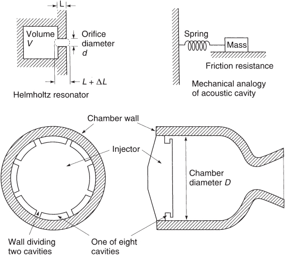
Figure 9–7 Simplified diagram of acoustic energy absorber cavities at the periphery of an injector. In the thrust chamber the cavity restriction is a slot (in the shape of sections of a circular arc) and not a hole. Details of the chamber cooling channels, injector holes, or internal feed passages are not shown.
Absorption cavities designed as Helmholtz resonators placed in or near the injector face offer relatively high absorption bandwidths and energies per cycle. Such resonators dissipate energy twice each cycle because jets are formed upon inflow and outflow. Modern design practices favor acoustic absorbers over baffles. The rocket engine shown in Fig. 8–2 has acoustic absorption cavities in the chamber wall at a location next to the injector.
The resonance frequency f of a simple Helmholtz cavity can be estimated as
Here, a is the local acoustic velocity, A is the restrictor area [![]() ], and other symbols are as shown in Fig. 9–7. ΔL is an empirical factor between 0.05 and 0.9L to allow for any additional oscillating gas mass. It varies with the L/d ratio and the edge condition of the restricted orifice (sharp edge, rounded, chamfered). Resonators in thrust chambers are tuned or designed to perform their maximum damping at predicted frequencies.
], and other symbols are as shown in Fig. 9–7. ΔL is an empirical factor between 0.05 and 0.9L to allow for any additional oscillating gas mass. It varies with the L/d ratio and the edge condition of the restricted orifice (sharp edge, rounded, chamfered). Resonators in thrust chambers are tuned or designed to perform their maximum damping at predicted frequencies.
Small changes in injector geometry may cause unstable combustion to become stable and vice versa. New injectors, therefore, use geometry designs of proven, stable prior units with the same propellants. For example, the individual pattern of concentric tube injector elements used with gaseous hydrogen and liquid oxygen (shown in Fig. 8–4d) are likely to be more stable when the hydrogen gas is relatively warm and its injection velocity is at least 10 times larger than that of the liquid oxygen.
There are other combustion‐driven vibration remedies besides baffles and resonant cavities. They include higher injector pressure drops or higher injection velocities, avoidance of resonances from certain key engine component structures, changes of critical injector dimensions, and changing or modifying the propellants. References 9–2 and 9–6 describe several other methods, such as cooled flame holders, critical dimensions of injector elements, varying the number of injector elements and their distribution over the chamber cross section, making the mixture ratio nonuniform near the face of the injector, and/or adding temporary consumable baffles, which are effective only during starting. Small solid particulates in the reaction gas may cause some damping in nozzle oscillating flows.
In summary, the designer needs to (1) be familiar with and use data from prior successful engines and simulation programs to establish key design features in order to estimate all likely resonances of the new engine and its major components, (2) design the feed system and structure to avoid these identified resonances, (3) use an injector design robust enough to provide appropriate mixing and propellant dispersion and be resistant to disturbances, and if needed, (4) include tuned damping devices (such as cavities) to overcome acoustic oscillations. To validate that a particular thrust chamber is stable, it is necessary to test it over the entire range of likely operating conditions without encountering instabilities. Analyses are needed (e.g., Ref. 9–24) to determine the maximum and minimum likely propellant temperatures, the maximum and minimum probable chamber pressures, and the highest and lowest mixture ratios, using a propellant budget such as shown in Section 11.1. Determining these ranges then establishes the variations of test conditions for the experiments. Presently, because of an improved understanding, the amount of testing needed to validate stability has been greatly reduced compared to that required 30 to 50 years ago.
PROBLEMS
- For a certain liquid propellant thrust chamber the following data are given:
Assume the gas composition and temperature to be uniform in the cylindrical chamber section. Stating any other assumptions that may be needed, determine the approximate resonance frequencies in the first longitudinal, radial, and tangential modes.Chamber pressure 68 MPa Chamber shape Cylindrical Internal chamber diameter 0.270 m Length of cylindrical section 0.500 m Nozzle convergent section angle 45° Throat diameter and radius of wall curvature 0.050 m Injector face Flat Average chamber gas temperature 2800 K Average chamber gas molecular weight 20 kg/kg‐mol Specific heat ratio 1.20 - Discuss how the three frequencies from Problem 1 will change with changes of combustion temperature, chamber pressure, chamber length, chamber diameter, and throat diameter.
- Discuss why heat transfer increases during combustion instabilities?
- Prepare a list of steps for undertaking a series of tests to validate the stability of a new pressure‐fed medium sized liquid bipropellant rocket engine. State your assumptions.
- Estimate the resonant frequency for a set of each of nine cavities similar to Fig. 9–7. Here, the chamber diameter
 , the slot width is 1.0 mm, and the width and height of the cavity are each 20.0 mm. The walls separating the individual cavities are 10.0 mm thick. Assume
  ,
,  , and
, and  .
.
REFERENCES
- 9–1. K. K. Kuo, Principles of Combustion, 2nd ed., John Wiley & Sons, Hoboken, NJ, 2005.
- 9–2. V. Yang and W. Anderson (Eds.), Liquid Rocket Engine Combustion Instability, Vol. 169 of Progress in Astronautics and Aeronautics, AIAA, 1995, in particular Chapter 1, F.E.C. Culick and V. Yang, “Overview of Combustion Instabilities in Liquid Propellant Rocket Engines.”
- 9–3. M. S. Natanzon and F. E. C. Culick, Combustion Instability, Progress in Astronautics and Aeronautics, Vol. 222, AIAA, Reston, VA, 2008.
- 9–4. W. Sirigano, A. Merzhanov, and L. De Luca, Advances in Combustion Science: In Honor of Ya. B. Zel'dovich, Progress in Astronautics and Aeronautics Series, V‐173, American Institute of Aeronautics and Astronautics, 1997.
- 9–5. D. T. Harrje (Ed.), “Liquid Propellant Rocket Combustion Instability,” NASA SP‐194, U.S. Government Printing Office, No. 3300–0450, 1972; NASA NTRS Doc. ID 19720026079; http://hdl.handle.net/2060/19720026079
- 9–6. G. P. Sutton, History of Liquid Propellant Rocket Engines, AIAA, 2006, Chapter 4.10, “Combustion and Vibrations,” and Chapter 8.4, “NPO Energomash.”
- 9–7. V. Yang, M. Habiballah, J. Hulka and M. Popp (Eds.), Liquid Rocket Thrust Chambers: Aspects of Modeling, Analysis and Design, Progress in Astronautics and Aeronautics (server), Vol. 200, American Institute of Aeronautics and Astronautics, Reston, VA, 2004; K. Kobayashi et al., “Studies on Injection‐Coupled Instability for Liquid Propellant Rocket Engines,” AIAA Paper 2015‐3843, Orlando, FL, 2015.
- 9–8. B. R. Lawver, “Photographic Observations of Reactive Stream Impingement,” Journal of Spacecraft and Rockets, Vol. 17, No. 2, Mar.—Apr. 1980, pp. 134–139.
- 9–9. M. Tanaka W. Daimon and I. Kimura, “Explosion Phenomena from Contact of Hypergolic Liquids,” Journal of Propulsion and Power, Vol. 1, No. 4, 1985, pp. 314–316; doi: 10.2514/3.22801; B. R. Lawver, “Photographic Observations of Reactive Stream Impingement,” Journal of Spacecraft and Rockets, Vol. 17, No. 2, Mar.–Apr. 1980, pp. 134–139; doi: 10.2514/3.57719.
- 9–10. R. I. Sujith, G. A. Waldherr, J. I. Jagoda, and B. T. Zinn, “Experimental Investigation of the Evaporation of Droplets in Axial Acoustic Fields,” Journal of Propulsion and Power, Vol. 16, No. 2, Mar.–Apr. 2000, pp. 278–285; doi: 10.2514/2.5566.
- 9–11. P. Y. Liang, R. J. Jensen, and Y. M. Chang, “Numerical Analysis of the SSME Preburner Injector Atomization and Combustion Process,” Journal of Propulsion and Power, Vol. 3, No. 6, Nov.–Dec. 1987, pp. 508–513; doi: 10.2514/3.23018.
- 9–12. M. Habiballah, D. Lourme, and F. Pit, “PHEDRE—Numerical Model for Combustion Stability Studies Applied to the Ariane Viking Engine,” Journal of Propulsion and Power, Vol. 7, No. 3, May–Jun. 1991, pp. 322–329; doi: 10.2514/3.23330.
- 9–13. M. L. Dranovsky (author), V. Yang, F. E. C. Culick, and D. G. Talley (Eds.), Combustion Instability in Liquid Rocket Engines, Testing and Development; Practices in Russia, Progress in Astronautics and Aeronautics, Vol. 221, AIAA, Reston, VA, 2007.
- 9–14. B. W. Oppenheim and S. Rubin, “Advanced Pogo Analysis for Liquid Rockets,” Journal of Spacecraft and Rockets, Vol. 30, No. 3, May–Jun. 1993, pp. 360–373; doi: 10.2514/3.25524.
- 9–15. K. W. Dotson, S. Rubin, and B. M. Sako, “Mission Specific Pogo Stability Analysis with Correlated Pump Parameters,” Journal of Propulsion and Power, Vol. 21, No. 4. Jul.–Aug. 2005, pp. 619–626; doi: 10.2514/1.9440.
- 9–16. T. Shimura and K. Kamijo, “Dynamic Response of the LE‐5 Rocket Engine Liquid Oxygen Pump,” Journal of Spacecraft and Rockets, Vol. 22, No. 7, Mar.–Apr. 1985, pp. 195–200; doi: 10.2514/3.25731.
- 9–17. J. C. Melcher and R. L. Morehead, “Combustion Stability Characteristics of the Project Morpheus Liquid‐Oxygen/Liquid‐Methane Main Engine,” AIAA Paper 2014‐3681, July 2014.
- 9–18. K. Shipley and W. Anderson, “A Computational Study of Transverse Combustion Instability Mechanism,” AIAA Paper 2014‐3679, Cleveland, OH, Jul. 2014.
- 9–19. J. Pieringer, T. Settelmayer, and J. Fassel, “Simulation of Combustion Instabilities in Liquid Rocket Engines with Acoustic Perturbation Equations,” Journal of Propulsion and Power, Vol. 25, No. 5, 2009, pp. 1020–1031.
- 9–20. E. Kirner, W. Oechslein, D. Thelemann, and D. Wolf, “Development Status of the Vulcain (HM 60) Thrust Chamber,” AIAA Paper 90‐2255, Jul. 1990.
- 9–21. Guidelines for Combustion Stability Specifications and Verification Procedures for Liquid Propellant Rocket Engines,” CPIA Publication 655, Chemical Propulsion Information Agency, John Hopkins University, Jan. 1997.
- 9–22. V. Yang, D. D. Ku, M. L. R. Walker, and L. T. Williams, Daniel Guggenheim School of Aerospace Engineering, Georgia Institute of Technology, “Liquid Oxygen (LOX)/Kerosene Rocket Engine with Oxidizer –Rich Preburner, Staged Combustion Cycles”, for NASA Marshall Apace Flight Center/Jacobs Technology, December 10, 2013.
- 9–23. T. L. Acker and C. E. Mitchell, “Combustion Zone–Acoustic Cavity Interactions in Rocket Combustors,” Journal of Propulsion and Power, Vol. 10, No 2, Mar.–Apr. 1994, pp. 235–243; doi: 10.2514/3.23734.
- 9–24. J. Garford, B. Barrewitz, S. Rari, and R. Frederic, “An Analytical Investigation Characterizing the Application of Single Frequency/Acoustic Modulation for High Frequency Instability Suppression,” AIAA Paper 2014–3679, Cleveland, OH, July 2014.