
3.3 Autostereoscopic Display
Instead of splitting left and right view image with the aided glasses at the viewer side for a stereoscopic display, the autostereoscopic display adopts the spatial multiplexing method to direct light emitted by pixels belonging to different views to the corresponding eyes. According to how the light-directing mechanism and optical effect are adopted, in general, we can categorize the autostereoscopic display into two major approaches: occlusion-based and refraction-based.
3.3.1 Occlusion-Based Approach
The occlusion-based approach exploits the parallax effects from the human visual system by utilizing the straight line direction characteristics of light. Imagining watching a scene through a small pinhole with the left eye only or the right eye only, each eye will observe a different image owing to the viewing angle and the occlusion caused by the opaque areas around the pinhole. By carefully applying this principle, one can build a parallax barrier display with a two-layer design as shown in Figure 3.1. The back layer consists of a pixelated emissive display panel, such as LCD, which interleaves the pixels from the left image and the right image such that the odd column pixels show the image for one eye and the even column pixels for the other eye. The front layer consists of an opaque layer with narrow regularly spaced vertical slits to allow light pass only to the desired viewing eye.
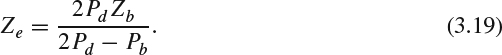
Since the light emitted from the left and right pixels is directed/blocked by the parallax barrier, the viewers need to watch the stereo image pair from the designed position, or so called viewing zone or sweet spot defined by the display. We use Figure 3.2 to illustrate the fundamental design principle for the parallax barrier. Denote the viewing distance between the viewers and the LCD panel as Ze, the distance between the parallax barrier and the emissive display panel as Zb, the viewing distance between viewers and parallax barrier as Zeb (Zeb = Ze − Zb), the emissive display pixel pitch as Pd, the parallax barrier slit pitch as Pb, and the distance between the left eye and the right eye as Pe. By applying similar triangular geometry, we have the following equation:
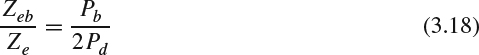

Figure 3.1 Illustration of parallax barrier display.
Bringing Zeb = Ze − Zb to (3.18), the viewing distance Ze for best viewing quality can be expressed as
The other triangular geometry equation can be formed as:

Then, the pitch of the parallax barrier Pb can be expressed as:

Substituting (3.19) to (3.21), we obtain:
The above equation indicates that the design of the barrier pitch should be less than twice the display pixel pitch.
Figure 3.2 Design principle of parallax barrier display.
Multiple viewing zones are formed in terms of the viewing distance and the viewing angle. As illustrated in Figure 3.3, as the viewer moves horizontally in front of the parallax barrier display and watches the display from different angles, he/she will leave one viewing zone and enter the next one. When a viewer watches a 3D video from the defined viewing zone, light from partial pixels belonging to different view may enter the opposite eye and cause crosstalk artifacts. When a viewer straddles between two different viewing zones, the viewer will experience pseudoscopic (reversed stereo) image where the left eye perceives the image representing the right view and the right eye observes the image representing the left view.
The crosstalk caused by the imperfect separation of the left and right images can be alleviated by reducing the pitch of the opaque slit aperture. However, reducing the pitch of slit aperture blocks more light from the emissive pixels and causes more loss of light. The other way to alleviate the crosstalk is to place the parallax barrier between the backlight and the LCD. The drawback brought by this kind of design is that the intensity needs more control for uniformity. Therefore, the tradeoff between crosstalk and the light efficiency is the major problem in the occlusion-based approach.
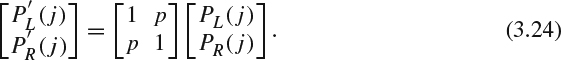
Besides the hardware solution, the crosstalk can be reduced by software solutions, such as precorrecting the video signals before displaying the left and right image [9]. Denote the intensity value of the jth row for each column at the left image and right image as IL(j) and IR(j), respectively; and denote the perceived intensity value at the jth row for each column at the left image and right image as BL(j) and BR(j) respectively. Assume the leakage from the other view to one view as p. Then, the perceived value for the pixel pair (affected by the crosstalk) can be expressed as a linear combination of the original left and right image:

Figure 3.3 Viewing zone and pseudoscopic image.

If the original pixel value is precorrected to PL(j) and PR(j), similar to (3.23), the perceived signal of the precorrected pixel pair (affected by crosstalk) can be represented as
The goal for this precorrection process is to make the perceived signal of the precorrected value as close to the original pixel value as possible, namely:
Substituting (3.25) to (3.24), the optimal precorrected pixel pair can be calculated as follows:

Besides the direct-view display shown above, the occlusion-based approach can be implemented through projectors by using two parallax barriers [10]. The parallax barrier projector consists of four layers: multiple 2D projectors at the lowest layer, the first layer of parallax barrier, a projection screen, and the second layer of parallax barrier on the top. The first parallax barrier controls the output of the projectors such that the size of image pixels on the projection screen matches the width of slit aperture. The functionality of the image pixel on the projection screen is similar to the pixelated emissive display panel used in the direct-view parallax barrier display. The second parallax barrier is placed in front of the projection screen and its functionality is the same as the parallax barrier used in direct-view display.
3.3.2 Refraction-Based Approach
Light changes its direction when it passes through mediums with different refractive index. We could take the advantage of this refraction property to direct the light through optical systems to our desired direction. For the 3D direct-view display application, lenticular technology places a vertically cylindrical microlens in front of the pixelated emissive display panel, as shown in Figure 3.4. Each vertical microlens is placed in front of two corresponding columns of pixels and the light from each pixel belonging to either left or right images will be directed to its targeted direction. One could further extend the refraction methodology to have a display equipped with both horizontal and vertical parallax, which is normally called an integral image display. Instead of using cylindrical microlenses, the integral image display uses a large number of small convex lenslets to pass light to its intended direction. These convex lenslets are arranged as a regular 2D array, or fly's eye, in the integral imaging display. Each microlens directs light to the targeted horizontal and vertical directions to generate the required parallax.

Figure 3.4 Illustration of lenticular display.

Figure 3.5 Design principles of lenticular display.
Similar to the parallax barrier display, the viewing distance Ze for the best viewing quality can be found via similar triangles in Figure 3.5 as:

Then, the pitch of the lenticular Pl can be expressed as:

There are several common major challenges in the design of refraction-based 3D display. The top two concerns are the alignment issue and intensity variation. As the refraction-based system is designed to manipulate light to the targeted direction, any slight misalignment between the lenticular array and pixelated emissive display panel will cause distortion for the perceived image. This problem will become worse when the required image dimension increases. The second issue arises when the viewer walks along the viewing zone: he/she will observe the brightness changes. Additional challenges based on the lenticular optics manufacturing are the additional coating needed on the surface of lenticular lens to alleviate the reflection from the viewer side and handling the light scatting inside the lenticular lens.
Besides the direct-view system, one could also apply the refraction-based approach to 3D projector design [11]. Similar to the occlusion-based 3D projector, the lenticular projector also consists of four layers: 2D projectors at the lowest layer, the first layer of lenticular screen, one projection screen, and the second layer of lenticular screen on the top.
To display a stereo color image, each pixel with square ratio consists of three subpixels alternating horizontally as shown in Figure 3.6a. Each subpixel has vertical rectangle ratio to represent different primary colors, namely, red, green, and blue. Each color subpixel has its own viewing zone and the overall observed combined color depends on the viewing angle as illustrated in Figure 3.6b. In some viewing zones, the viewer may encounter the color separation (or color dispersion) problem that the observed color is distorted.
Since the occlusion-based and refraction-based approach adopt the spatial multiplexing method, subject to the limited number of pixels in the horizontal resolution, the left image and the right image pixels are column interleaved to represent the stereo image. The simplest way is to put the odd column of the left view image at the odd column LCD pixels and the even column of the right view image at the even column LCD pixels. By doing so, the pixel perceived in each eye is only half resolution along the horizontal direction for a two-view system. Approaches with low-pass filtering with half decimation should be adopted to alleviate the aliasing during the half-resolution image generation process [12]. Note that the interleaving can be further implemented at the subpixel level, as seen in Figure 3.6a, where the odd and even subpixel columns display the image from left and right view, respectively.
The pixel subsampling problem will be relieved with the newly introduced higher resolution 4K (3840×2160) display. Since the number of pixels in the 4K display in the horizontal direction is twice the resolution of HD 2K (1920×1080) video, the 4K display should be able to display the full resolution of the original 2K content in two views.
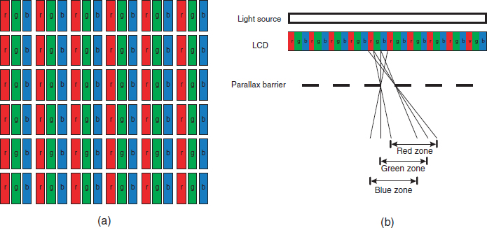
Figure 3.6 Illustration of subpixels in autostereoscopic display. The rectangle box with label “r”, “g”, and “b” represent the red, green, and blue subpixel, respectively. (a) RGB subpixel layout. (b) Viewing zone for each color component.
Rather than applying spatial multiplexing on one single LCD panel, a full-resolution, full color, and high intensity system for each view can be realized by using dual LCD panels, each of which is perpendicular to the other. The back layer of each LCD panel is equipped with a field len to direct light from light source through LCD. A half mirror is placed 45° between two LCD panels to further direct each view to its corresponding eye [13]. This system is shown in Figure 3.7. Note that as the position of the light source changes, the viewing window changes, too. We can take this property to design a 3D display to support multiple viewers and provide greater freedom to change viewing angles. To support multiple viewers, we can install additional light sources, and each light source will direct light to a different viewing zone. With a head-tracking system and a steerable light source, the light will be directed to the viewer's eyes.