
![]()
State Machine Workflows
In the previous two chapters I briefly skimmed over the basics of state machine workflows. This chapter will quickly have you building state machine workflows to model some really cool scenarios, but before we get going, let’s review the basics.
State machine workflows provide an alternative approach for modeling human behavior when the flow of events cannot usually be predicted. An example is an approval process when events drive the flow of execution for the process, usually as external events and guide transitions between other possible states. Basic characteristics of state machine workflows include an initial and a final state. This means that a process must have a predefined state for starting a process and a final state that represents that the process has completed. They also have a flexible flow of logic that can cycle back and forth between states within a workflow. Because external events drive a state machine workflow, they are reactive in nature (see Figure 4-1).
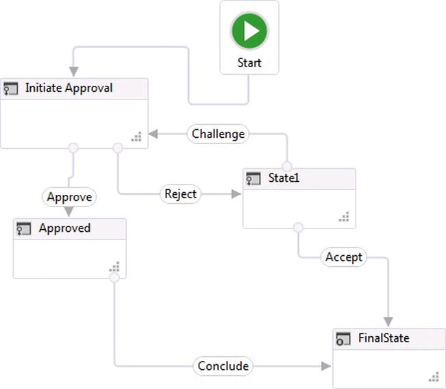
Figure 4-1. Approval as state machine
State machine workflows were a part of the initial release of WF but they were not included with the release of WF4. One reason was the thought that flowchart workflows would be a natural alternative for modeling state machine processes. Also, state machine workflows were probably not included in WF4 because of the short window for rewriting the entire WF framework and the lack of time to design a new state machine workflow. After WF4 was released, and in response to strong demand from developers, a new state machine workflow experience was introduced within .Net 4.0 Platform Update 1, which is also included with WF4.5. Compared to the state machine workflows released with WF 3.x, there is a much better modeling experience using the WF designer.
The best part about using state machine workflows is that they seamlessly integrate with sequential and flowchart workflows, which was a complex task within WF 3.x. Because each type of workflow presents its own rich features for modeling work, integrating multiple workflows combines the flexibility for modeling complex business processes. A workflow can inherit the functionality and benefits gained from using different types of workflows to work together.
Most of the workflows I have built in the past have included state machines for long-running processes, so I think re-introducing state machines into WF4.5 was a good thing. Primarily, long-running process flow usually includes some human decision making.
Recently I was working with a client who asked me to make some enhancements to an existing online orders application. The ordering process integrated with other external systems, and I was tasked with reviewing the code to understand where specific changes could be made. I could not help thinking how the system could have benefitted by implementing a state machine workflow using WF.
First, each step of the ordering process relied on either a customer or employee to make a decision. This is a key characteristic when making the decision for using state machines. Second, there was no documentation I could use to understand the process. Thus I had to reverse-engineer the current application by reviewing the code. If WF had been used, there would at least have been a visual representation of a workflow that I could have used instead of looking through code to understand the logic. Third, the current application could have benefited from some concurrent logic that could have been easily implemented with out-of-the-box activities. For instance, two of the external systems could have been accessed at the same time for retrieving order information.
This chapter will demonstrate when state machine workflows should be used to model business processes based on characteristics and requirements. It will also walk you through the steps for implementing state machine workflows within an application.
State Machine Components
Let’s take a look at the components that WF4.5 offers to developers for building state machines. The components described in this section of the chapter are available for implementing state machine workflows in WF4.5.
State Machine Workflow
The state machine workflow activity resides within the namespace System.Activities.Statements.StateMachine and provides the canvas for adding other activities. It is the first activity used for orchestrating state machine workflows. One of the major features in WF4 was removing the boundary for the designer to care about the type of workflow being built. Therefore, when creating a new workflow project, the default canvas for a workflow is blank. By adding a state machine workflow to the designer canvas, additional state activities can be dragged to the designer to model states within a process (see Figure 4-2).
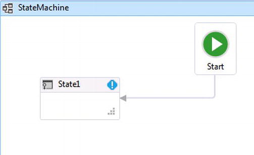
Figure 4-2. State machine workflow
When a state machine workflow is dragged to the designer, a design time exception is automatically indicated within the initial default state, State1. Hovering over the exclamation mark reveals a pop-up tooltip that says, "State1 must have at least 1 transition." This really means that another state needs to be manually added and connected to State1 before the workflow will compile.
State
A state resides within the namespace System.Activities.Statements and is a sealed class, meaning that it is not intended to be used as a base class for building custom objects. It also does not inherit from any of the base activity objects, which means that is not an actual WF activity. States represent a logical position that a workflow can have at any given time as the workflow executes. Each state on a workflow has an entry and exit action. These are containers for adding additional child activities for modeling logic and executing units of work as the state changes from one to another (see Figure 4-3). There is also a Transition(s) section that reflects the transitions are directed to and away from a state.
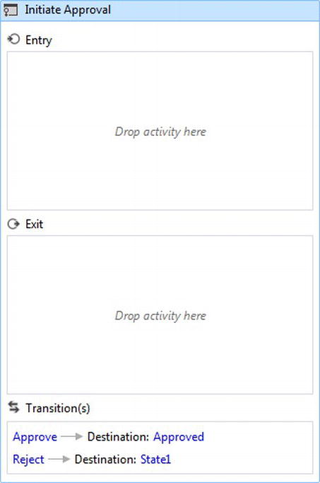
Figure 4-3. Entry and exit activity containers
State Entry
A state machine workflow by default provides a default state (see Figure 4-2), the first state that is transitioned to automatically when a workflow is executed. When a transition is made to another state, the entry activity container executes. Figure 4-4 shows the entry of a state that contains a Sequence activity that contains WriteLine activity that says Entered State1. This activity will indicate to the console that the workflow is being transitioned to another state. I added an If activity to demonstrate that the state entry itself executes as a workflow its self.
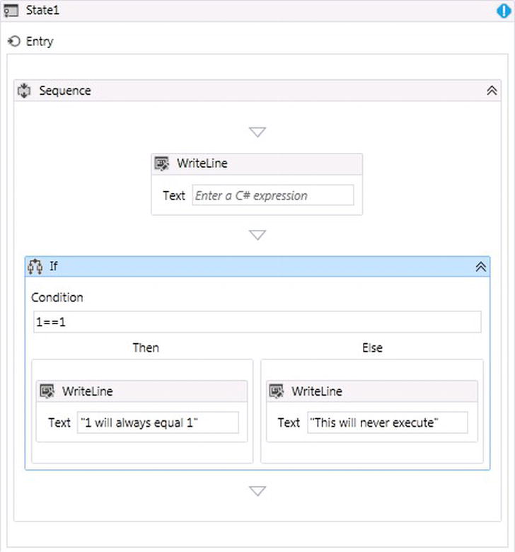
Figure 4-4. State entry activities
After adding activities to a state’s entry action, the next time the complete state machine workflow is viewed within the designer, there will be a circle with an arrow pointing into the left side that indicates the state has activities contained within its entry action (see Figure 4-5).
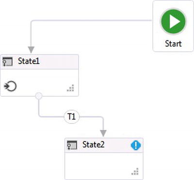
Figure 4-5. State1’s entry indicator arrow
State Exit
A state’s exit action also allows activities to be added for performing business logic as the state is transitioned to another state (see Figure 4-6).

Figure 4-6. State exit point
Figure 4-7 indicates that after adding activities to the exit action of a state, a circle appears within State1 with an arrow pointing out of the circle, indicating that activities exist while the state is about to transition to another state.

Figure 4-7. State1’s exit indicator arrow
Transitions
State machines use transitions for flowing from one state to another. The logical flow of states can be transitioned to and from one another within the same workflow; however, a transition can only flow in one direction. So if state changes from one state to another and then back to the original state, there must be two transitions to model the flow back and forth (see Figure 4-8).

Figure 4-8. Transitions
Each transition represents an event that is fired externally; transitions can only be executed from the current state of the workflow. Each event is described using a bookmark that can be called externally from the workflow (see Figure 4-9).
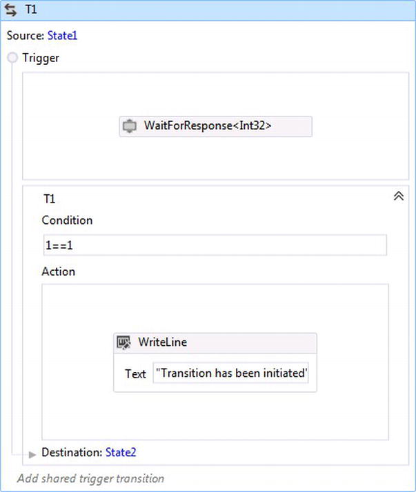
Figure 4-9. Transition trigger, condition, and action
A custom bookmark activity can be defined through code and is used for triggering the execution for a state machine transition. When a bookmark is initiated from the hosted WorkflowRuntime, the corresponding bookmark activity is executed initiating the execution for a transition. A transition’s trigger is used as a container for a bookmark activity.
Once the trigger has been fired from a bookmark activity, in order for the transition to succeed to another state, business logic can be described using an expression determining if the transition should succeed or fail.
After the condition passes for a triggered transition, the action allows additional activities for modeling business logic that should be performed as the transition completes from one state to another.
![]() Note The same bookmark can be defined for firing an external event for more than one transition. The condition for the transition uses an expression that determines which transition will execute.
Note The same bookmark can be defined for firing an external event for more than one transition. The condition for the transition uses an expression that determines which transition will execute.
The FinalState models the last unit of work performed within a business process before it finally ends. It is identified by a unique icon that differentiates it from the other states (see Figure 4-10). The FinalState is used to finalize any leftover work.

Figure 4-10. FinalState
Once the transition is made to the FinalState of the workflow, any last bit of logic can be executed because it contains an entry action for adding additional activities, just like regular states (see Figure 4-11).
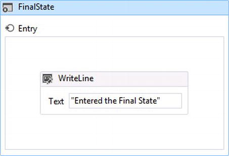
Figure 4-11. FinalState entry point
The main difference of the FinalState is that it does not have an exit action, because once the workflow has transitioned to the FinalState, there are no other states to transition to and the workflow completes.
With the WF designer enhancements in WF4.5, state activities no longer have to be manually connected to other states that do not already have a transition associated with them. Connecting states can now be automatic after a state is selected from the toolbox and dragged within close proximity to an existing state on the designer canvas.
In WF4.5, states can also be automatically connected in between states that are already associated through a transition, by positioning the mouse over a selected state from the toolbox and dragging it over an existing transition. When the activity is released, it becomes the middle transitional state between the other existing two.
Debugging State Machine States
The WF4.5 designer also allows breakpoints to be added to a state itself, indicating that a state is about to be executed during runtime (see Figure 4-12).
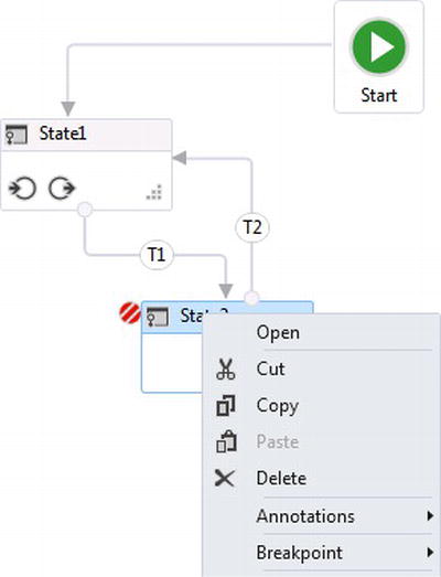
Figure 4-12. Red circles with diagonal white lines indicate that a breakpoint has been added onto state activities
State Machine Behavior
There are some behaviors for state machine workflows in WF I want to cover so that you are aware of them while building workflows. I will start off by demonstrating some of the behaviors by using functionality out of the box. I’ll use a standard workflow console application and the state machine workflow activity that will be extended for demonstration purposes.
Transition Requirement
Earlier I mentioned that after a new state machine workflow is added to the designer canvas, by default it will contain a single state as depicted in Figure 4-2, but a transition must be set to another state. This is the case for each state that is added to the workflow other than the FinalState, or an exception will be thrown for the latest state added to the workflow (see Figure 4-13).
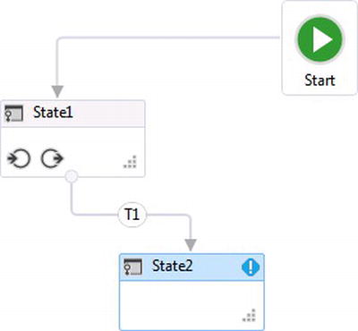
Figure 4-13. State transition requirement
Adding a FinalState to the workflow will satisfy the requirement; however, a transition can also be added back to State1 from State2 and this will also satisfy the requirement (see Figure 4-14).
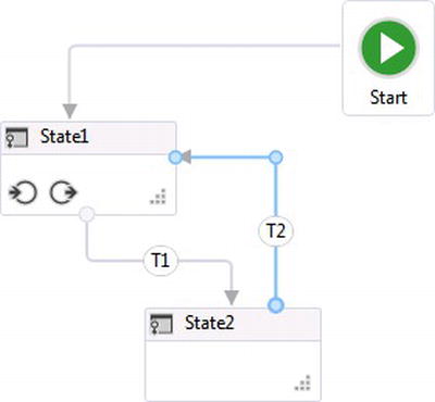
Figure 4-14. Circular transitions
As you can imagine, this could cause an infinite loop within the workflow depending on how the transition is implemented. In this case, the transition has not been altered after making the connection from State1 to State2. Therefore, there is no condition set up for the transition, which means that the transition will automatically execute. This can be demonstrated through the console window by adding two WriteLine activities within the states. Add one within the entry action of State1 saying Entered State1 and the other within the entry action of State2 saying Entered State2 (see Figure 4-15).
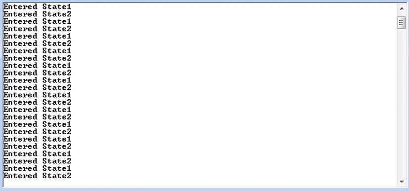
Figure 4-15. Demonstrating circular transition
Transition Conditions
A state can make more than one transition to another state. Figure 4-16 shows that State1 has two transitions to the FinalState of the workflow.
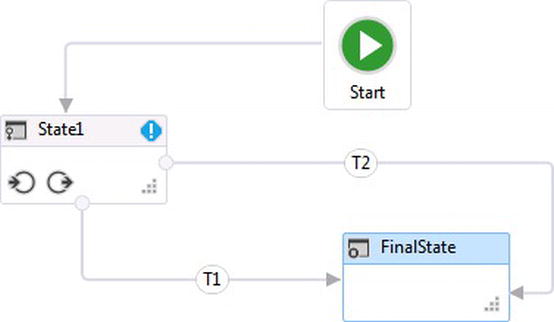
Figure 4-16. More than one state transition
When this happens, the condition of the transition has to be set. If not, you will get an error like in Figure 4-17.

Figure 4-17. Error message
To get rid of the exception, a condition using a C# or VB expression can be used. In this case, I used the C# expression, which is a new feature in WF4.5. The syntax is 1==1 since the workflow project is a C# project (see Figure 4-18).
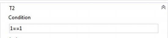
Figure 4-18. Transition expression
The problem is that one or more transitions from the same state can actually use the same expression (see Figure 4-19).
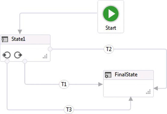
Figure 4-19. Multiple transitions with the same condition
If they do, the transitions will fire in the order that they were added to the workflow. This can be seen for workflows built with XAML by looking through the XML for a workflow indicated as the first transition within the transition’s XML element (see Listing 4-1). The good thing is that only one of the transitions will succeed, cancelling out the other transitions.
Listing 4-1. Possible Transitions with the Same Transition Condition
<State.Transitions>
          <Transition DisplayName="T1" sap2010:WorkflowViewState.IdRef="Transition_3">
            <Transition.Condition>
              <mca:CSharpValue x:TypeArguments="x:Boolean">1==1</mca:CSharpValue>
            </Transition.Condition>
            <Transition.To>
              <State x:Name="__ReferenceID0" DisplayName="FinalState" sap2010:WorkflowViewState.IdRef="State_3" IsFinal="True" />
            </Transition.To>
          </Transition>
          <Transition DisplayName="T2" sap2010:WorkflowViewState.IdRef="Transition_4" To="{x:Reference __ReferenceID0}">
            <Transition.Condition>
              <mca:CSharpValue x:TypeArguments="x:Boolean">1==1</mca:CSharpValue>
            </Transition.Condition>
          </Transition>
          <Transition DisplayName="T3" sap2010:WorkflowViewState.IdRef="Transition_5" To="{x:Reference __ReferenceID0}">
            <Transition.Condition>
              <mca:CSharpValue x:TypeArguments="x:Boolean">1==1</mca:CSharpValue>
            </Transition.Condition>
          </Transition>
        </State.Transitions>
![]() Tip A workflow created using the designer has a XAML file that can be viewed by right-clicking the workflow and selecting View Code.
Tip A workflow created using the designer has a XAML file that can be viewed by right-clicking the workflow and selecting View Code.
If a bookmark were to be used within trigger for transition T4, the next transition would fire within the transition’s XML element because the T4 transition would then be waiting on an external event.
A transition trigger is what really drives a transition into execution. The condition is merely used to determine if the transition is successful for transitioning to the next state; therefore it does make sense for more than one transition of a state to use the same condition. In fact, the same bookmark could be used for more than one transition within the same state. This behavior is called a shared trigger because the bookmark is what drives the execution for more than one transition. However, it’s not common for the same bookmark to be used more than once with the same condition. See Listing 4-2.
Listing 4-2. WaitForResponse Bookmark Activity
using System;
using System.Collections.Generic;
using System.Linq;
using System.Text;
using System.Activities;

namespace FlowFocus.WF.Activities
{
    public sealed class WaitForResponse<TResult> : NativeActivity<TResult>
    {
        public WaitForResponse()
            : base()
        {

        }

        public string ResponseName { get; set; }

        protected override bool CanInduceIdle
        {
//override when the custom activity is allowed to make he workflow go idle
            get
            {
                return true;
            }
        }

        protected override void Execute(NativeActivityContext context)
        {
            context.CreateBookmark(this.ResponseName, new BookmarkCallback(this.ReceivedResponse));
        }

        void ReceivedResponse(NativeActivityContext context, Bookmark bookmark, object obj)
        {
            this.Result.Set(context, (TResult)obj);
        }
    }
}
![]() Caution State transitions for the same state should not share the same bookmark trigger and the same condition. This behavioral logic would be considered redundant.
Caution State transitions for the same state should not share the same bookmark trigger and the same condition. This behavioral logic would be considered redundant.
USING BOOKMARKS FOR STATE MACHINES
I will use the code in Listing 4-1 to build a generic bookmark activity to demonstrate using bookmarks with state machine transitions for different scenarios. To create a bookmark using the code in Listing 4-2 and walk through the different scenarios, create a new Visual Studio 2011 solution by following these steps.
- Open Visual Studio 2012 and create a new Project.
- Select the Workflow template to see a list of installed workflow templates.
- Select Workflow Console Application, and name it Chapter4.StateMachine.
- Right-click on the project and select Add
 Class.
 - Name the new class file WaitForResponse.cs.
- Delete the default code in WaitForResponse.cs and replace it with the code from Listing 4-1.
- Compile the project. At this point there is now a WaitForResponse activity that will be used for adding bookmarks to the state machine workflow.
- Click on the default workflow file, Workflow.xaml, and add a new StateMachine activity from the toolbox to the designer canvas.
- Drag a FinalState over to the workflow and hover over the existing State1 state. Arrows will appear on State1 and the bottom arrow will bold as the FinalState is hovered over it. Drop the FinalState onto the bottom arrow as it bolds and it will automatically provide a new transition called T1 to the FinalState (see Figure 4-20).

Figure 4-20. Auto connecting FinalState
- To see the entry and exit activity containers within a state, double-click on State1.
- Drag a WriteLine activity from the toolbox and drop it within the entry container. Set the Text property for the activity to Entered State1.
- Double-click the FinalState activity and drag another WriteLine activity from the toolbox and drop it within the entry container. Set the Text property for the activity to Entered the FinalState.
Double-click transition T1 to view its trigger, condition, and action points. At the top of the toolbox, you will notice the WaitForResponse bookmark activity that you added earlier. Drag it from the toolbox and add it to the Trigger container. The Select Types box appears, requesting what type of data the bookmark is in charge of passing from the WorkflowRuntime to the active bookmark. The default value type in this case is Int32, and for simplicity Int32 will be used for executing the state-machine Transition. See Figure 4-21. If I needed to pass in a certain entity, like an order object, then I could browse for that order type and use it to pass in an order that I would like to appear in a workflow.

Figure 4-21. Adding WaitForResponse bookmark
- After selecting the bookmark type of Int32, the bookmark needs to be given a ResponseName property so the workflow knows which bookmark the WorkflowRuntime intends to resume. This is set within the Properties window while the new WaitForResponse activity has been selected. Set the ResponseName property to BookMarkResponse (see Figure 4-22).

Figure 4-22. WaitForResponse bookmark properties
- Usually there would be one last step to open up the Program.cs file and add Console.Read(); right after WorkflowInvoker.Invoke(workflow1); This will allow the console window to stay open after the workflow completes; however the workflow will not complete now because of the bookmark you added. The bookmark tells the workflow that it needs to wait for an event before it can complete, which is unlike the behavior you saw earlier in the chapter where transitions without triggers were automatically transitioning to other states (see Figure 4-23). The workflow can now be run; however the WriteLine activity that you placed within the FinalState activity will never write to the console because State1 never transitions.
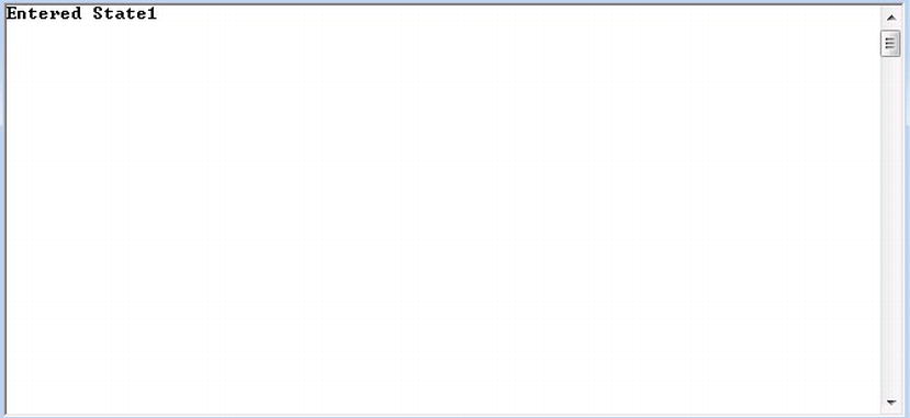
Figure 4-23. Workflow waiting on bookmark
![]() Tip The Result property of a bookmark can be set to a WF variable within the workflow so the value that is passed in through the bookmark can assist in executing logic within the workflow.
Tip The Result property of a bookmark can be set to a WF variable within the workflow so the value that is passed in through the bookmark can assist in executing logic within the workflow.
Hosting WF Bookmarks
Bookmarks will not work while using WorkflowInvoker.Invoke(). Bookmarks demand a closer intimacy with the WorkflowRuntime that WorkflowInvoker does not provide. Instead WorkflowApplication must be used for hosting workflows that request internal interaction with the WorkflowRuntime through bookmarks. The WorkflowApplication hosts a workflow on a separate thread from the hosting application. Because of this, delegates are set up for handling WorkflowRuntime events like when a workflow completes, aborts, goes idle, or encounters an unexpected exception.
The WorkflowApplication must be instantiated to host workflows. This is different than using the static WorkflowInvoker. I will demonstrate this using the same code that was created in the exercise “Using Bookmarks for State Machines.” Opening the Program.cs file will reveal the default code used for invoking Workflow.xaml (see Listing 4-3).
Listing 4-3. Default Program.cs
using System;
using System.Linq;
using System.Activities;
using System.Activities.Statements;

namespace Chapter4.StateMachine
{

    class Program
    {
        static void Main(string[] args)
        {
            // Create and cache the workflow definition
            Activity workflow1 = new Workflow1();
            WorkflowInvoker.Invoke(workflow1);
        }
    }
}
Because there are two threads executing, one for the application and the other for the workflow, the using statement, Using System.Threading must be added and WorkflowInvoker.Invoke(workflow1); can be removed. The WorkflowApplication code can now be added to host the workflow built in the previous exercise. The following code is added to instantiate the new host:
WorkflowApplication wfApp =
 New WorkflowApplication(workflow1);
The next code to add handles the synchronization between the two threads between the host and the workflow:
AutoResetEvent autoEvent = new AutoResetEvent(false);
The next piece of code that is needed is notification for when the workflow completes, using the WorkflowApplication host’s Completed action:
wfApp.Completed = delegate(WorkflowApplicationCompletedEventArgs e)
{
 Console.WriteLine("Workflow has completed!");
 autoEvent.Set();
};
Finally, the WorkflowApplicaton is started, and the WorkflowRuntime is notified that there is a bookmark for the workflow that is intended to resume workflow execution. The WorkflowApplication host uses the ResumeBookmark method to pass in the bookmark’s name and value:
wfApp.Run();
wfApp.ResumeBookmark("BookmarkResponse",Convert.ToInt32(Console.ReadLine()));
Console.ReadKey();
The above code will accept an entered value typed in from the console, and since the bookmark within the workflow in the exercise requires an integer, the value entered is converted to an integer. After the code mentioned above is added to Program.cs, the workflow can be run. The first console window that appears is pretty much the same as what you received in the exercise (see Figure 4-24)
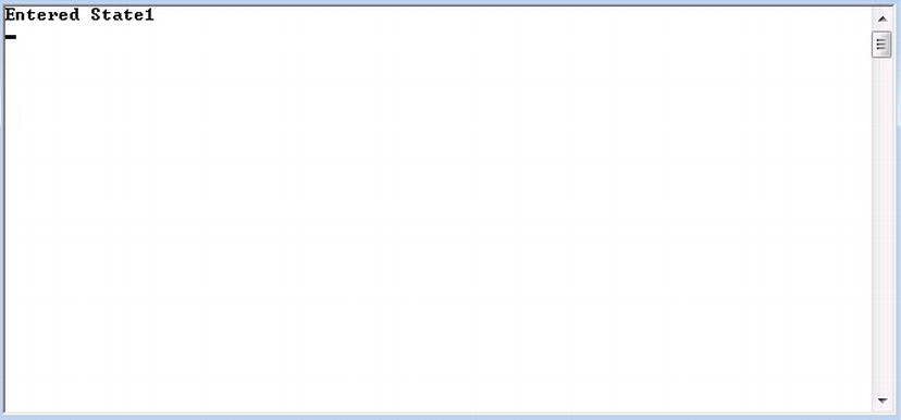
Figure 4-24. Workflow waiting on a bookmark to resume execution
At this point, entering any number and pressing Enter will resume execution of the workflow to completion (see Figure 4-25).
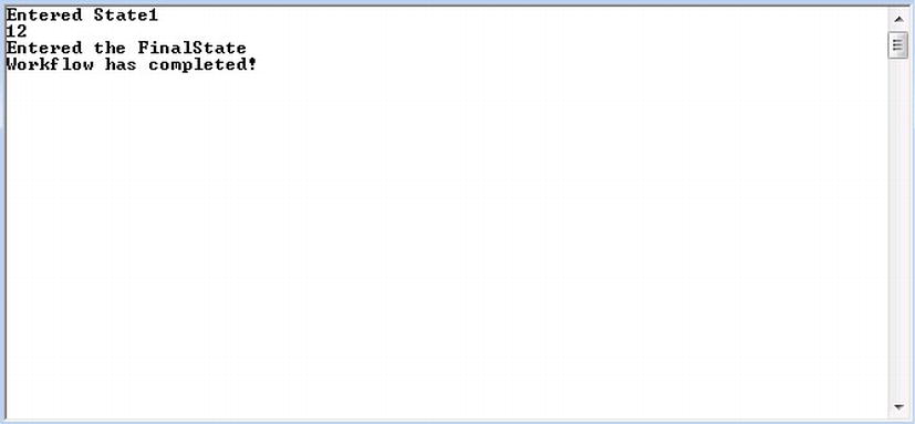
Figure 4-25. The workflow completing
Congratulations, you have now created a bookmark and resumed a state machine workflow from the hosting application.
Building State Machine Workflows
So far this chapter has helped you discover the components and basic behavior patterns used for building with state machine workflows, and it briefly introduced a new way of communicating externally to hosted state machine workflows using bookmarks. Now I want to show you how to tie this knowledge together and model a state machine starting off with a simple familiar process for driving an automobile. You will learn the following concepts:
- Hosting application
- Implementing state
- Wiring up transitions
- Shared triggers
Driving a car is an activity that most of us either do every day or are at least have some familiarity with performing, therefore modeling the process should be quite simple. The steps to modeling a process are another important exercise that WF requires, because while requirements are being analyzed, WF can be used for modeling the logical process. I have worked on many projects where I felt more comfortable using WF to model requirements than Visio, and WF allows state machines to model work at a higher level, so additional requirements can be discovered. But back to modeling driving an automobile: it may seem like an unrealistic business case, but to make the concept more interesting you might like to know that there is software already doing what I am about to demonstrate to you.
The first step in driving an automobile is getting in it. Well, since we are talking about states, before a driver can get in to a car, it must be parked. But I think I was on to something when I mentioned “getting in.” This could be modeled as a transition to another state. The next state could be to drive the car, or more specifically maybe the next step should be to start the engine. There are a bunch of other obvious things that should happen before putting an automobile in gear, such as the following:
- Fastening the seatbelt.
- Inserting the key.
- Locking the door.
This is why it is important to have requirements—because something that a stakeholder feels is very important could be different than what developers think should be implemented. Modeling the flow allows developers to use visual representations that can be used for driving additional requirements. To keep things simple, the states will model the following:
- Parked
- EngineStarted
- Neutral
- Reverse
- Drive
- TurnedOff
Something to note about these states is the indented section for Drive and Reverse. Indentation could either define states or even transition. One way to differentiate between the two is to identify a transition as an action and a state as a status. In this case they are states because they define a status of being in gear.
Out of the box, these bullets can be modeled into a logical flow without having to wire up anything within WF; you can just simply drag and drop states and connect them using transitions (see Figure 4-26).

Figure 4-26. Driving state machine model
Immediately there is an exception indicating that there is more than one transition that does not have a trigger associated with it. The other interesting thing is how the workflow modeled the bullets of
- Neutral
- Reverse
- Drive
A little bit of inferred logic indicates that Drive and Reverse must be set back to Neutral before the automobile can be turned off; however this representation could also be used to prove the case that this should be the only logical flow for turning off an automobile. Annotations can now be used in WF4.5 for indicating this logical decision. Annotations can be added to the workflow or to individual activities. Figure 4-27 indicates an annotation was added to the Neutral state to capture the requirement decision.

Figure 4-27. Activity annotation
Transition descriptions can also be added to make the state machine more descriptive. By default WF adds a “T,” followed by a sequential number that uniquely represents each transition. A transition has a DisplayName property that can be customized to represent the action that the transition will take while the transition occurs (see Figure 4-28). Selecting a transition, by clicking on it, allows the transition’s properties to be viewed within the Properties window, where the DisplayName property can be changed.
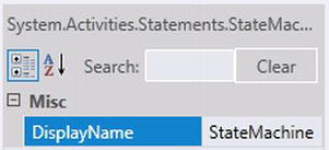
Figure 4-28. Transition’s DisplayName property
The goal for building workflows is to visually make a process’s logical flow of execution as easy as possible to interpret. Changing the names for the transitions of a workflow makes it look just as good as any other modeling tool used for producing process models (see Figure 4-29).

Figure 4-29. Descriptive transitions
State Machine Host
Since the Driving state machine workflow provides some of the same basic functionality as a production state machine workflow, the hosting application needs to provide additional functionality for hosting the workflow and giving the user feedback on how the workflow is responding. In the last example, I demonstrated how to build a simple console application used for hosting a state machine workflow through WF’s hosting provider WorkflowApplication. This time I will demonstrate how the driving workflow can be hosted within a Windows Presentation Foundation (WPF) application (see Figure 4-30), but first let’s walk through the Driving workflow.
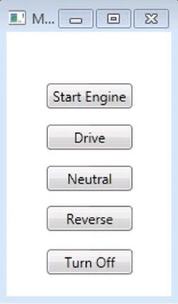
Figure 4-30. Driving workflow hosted in WPF
The transition descriptions added in Figure 4-29 really help to visually infer the modeled process for driving an automobile, but just to make sure the workflow is clear, let’s walk through how it should flow while it is executed. As the workflow is started, the first thing that happens is the workflow anticipates the automobile gear to be in Park, so the workflow will automatically transition its state to In Park. While In Park, the driver has the ability to start the engine. While In Park, the workflow indicates that the automobile has to be started and gear changed to neutral. The automobile can then be driven by changing the gear to Drive or the engine can be turned off. If the engine is turned off, you can see that the TurnedOff state uses a FinalState, so the workflow would then be completed, but if automobile’s gear is put into drive, then later the automobile can be put back into neutral or even reverse. Let’s now see how the workflow flows while it is hosted within the application, and how the hosting application functions and response to the driving workflow as it is being executed.
The hosting application built to host the driving workflow will instruct the workflow how it needs to flow as the buttons on the user interface (UI) are clicked. Commands are then communicated to the workflow through the WorkflowRuntime, using WF bookmarks that are associated when a button is clicked. Figure 4-30 shows that there are five buttons:
- Start Engine
- Drive
- Neutral
- Reverse
- Turn Off
Each button commands how the workflow will flow and react based on the workflows feedback. As the application is started, something interesting happens. The WorkflowRuntime is started and accepts the driving workflow state machine as the model that will be executed. As a result, the workflow starts the workflow’s state goes to In Park. Figure 4-31 illustrates how the UI reacts based on the workflow’s execution.
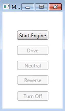
Figure 4-31. Start Engine application command
This feedback is then returned to the hosting WPF application; the results seen in Figure 4-32 mirror the same logic represented within the current state. Pressing the Start Engine button, the workflow is sent its first command through a bookmark to change its state to In Neutral. The workflow then communicates back to the hosting application the next possible transitions (see Figure 4-32).
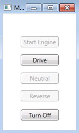
Figure 4-32. Drive and Turn Off application commands
If the Drive button is selected, the workflow flows to the In Drive state, and the workflow can then either flow back to the In Neutral state or the In Reverse state. The hosted application guides these choices by enabling the corresponding buttons (see Figure 4-33).
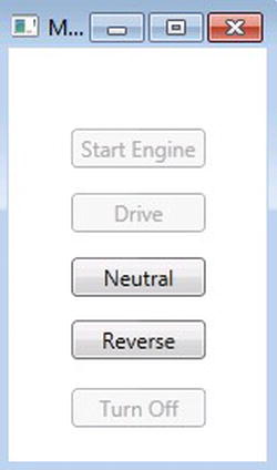
Figure 4-33. Neutral and Reverse application commands
The workflow can then go back to the In Neutral state or decide to go to the In Reverse state (see Figure 4-34).
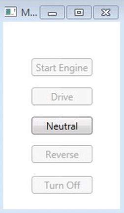
Figure 4-34. Neutral application command
Clicking the Neutral button will take the workflow back to the In Neutral state where the Drive and Turn Off buttons are available. Clicking the Turn Off button will then complete the workflow. Once the workflow has completed, all of the button commands are disabled, as you can see in Figure 4-35.

Figure 4-35. Hosting application indicates workflow completion
Now that you see how the hosting application functions with the driving state machine workflow work, I want to walk through the code. The first thing is the UI. If you are not familiar with WPF applications, it is similar to WF workflows because WPF uses XAML as its markup for defining its UI. This is much different if you are used to building Windows Forms applications.
I wanted it to be pretty simple to follow, since I want you to focus on the integrating interaction with the application and the WorkflowRuntime using the WorkflowApplication hosting provider. WPF uses code the same way as Windows Forms does for driving the UI, and building the UI is very similar to building a Windows Forms front end, too (see Figure 4-36).
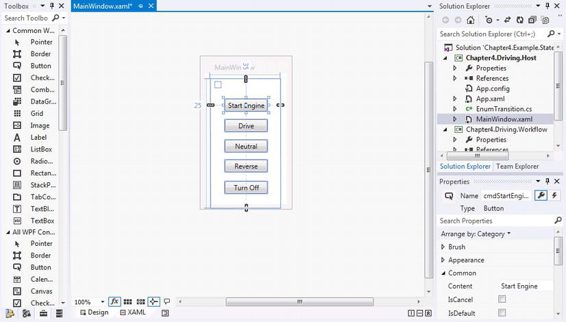
Figure 4-36. WPF hosting application UI
While controls are dragged from the toolbox, XAML is also being automatically built, representing the form as markup (see Listing 4-4).
Listing 4-4. UI Markup (MainWindow.xaml)
<Window x:Class="Chapter4.Driving.Host.MainWindow"
        xmlns="http://schemas.microsoft.com/winfx/2006/xaml/presentation"
        xmlns:x="http://schemas.microsoft.com/winfx/2006/xaml"
        Title="MainWindow" Height="269" Width="159.5">
    <Grid Margin="10,10,11,-6" RenderTransformOrigin="0.5,0.5">
        <Grid.RenderTransform>
            <TransformGroup>
                <ScaleTransform/>
                <SkewTransform/>
                <RotateTransform Angle="-0.09"/>
                <TranslateTransform/>
            </TransformGroup>
        </Grid.RenderTransform>
        <Button Name="cmdStartEngine" Content="Start Engine" HorizontalAlignment="Left"
 Margin="25,35,0,0" VerticalAlignment="Top" Width="75" Click="cmdStartEngine_Click"/>
        <Button Name="cmdDrive" Content="Drive" HorizontalAlignment="Left"
 Margin="25,71,0,0" VerticalAlignment="Top" Width="75" Click="cmdDrive_Click"/>
        <Button Name="cmdNeutral" Content="Neutral" HorizontalAlignment="Left"
 Margin="25,107,0,0" VerticalAlignment="Top" Width="75" Click="cmdNeutral_Click" />
        <Button Name="cmdReverse" Content="Reverse" HorizontalAlignment="Left"
 Margin="25,142,0,0" VerticalAlignment="Top" Width="75" Click="cmdReverse_Click"/>
        <Button Name="cmdTurnOff" Content="Turn Off" HorizontalAlignment="Left"
 Margin="25,180,0,0" VerticalAlignment="Top" Width="75" Click="cmdTurnOff_Click"/>
        <Label Name="lblEvent"  HorizontalAlignment="Left" Margin="8,5,0,0" VerticalAlignment="Top"/>
    </Grid>
</Window>
After getting the UI built, a representation for the transitions within the workflow are defined using enums. This is shown in Listing 4-5.
Listing 4-5. Transition Enums (EnumTransition.cs)
using System;
using System.Collections.Generic;
using System.Linq;
using System.Text;
using System.Threading.Tasks;

namespace Chapter4.Driving.Host
{
    public enum DriveTransition
    {
        StartEngine,
        TurnOff,
        InGear,
        PutInReverse,
        PutInNeutral,
    };
}
Other than the workflow, these are the only files that are external to the WPF hosting application. The actual code that works with the WorkflowApplication is represented in Listing 4-6.
Listing 4-6. Hosting Application (MainWindow.xaml.cs)
using System;
using System.Activities;
using System.Collections.Generic;
using System.Linq;
using System.Text;
using System.Threading;
using System.Threading.Tasks;
using System.Windows;
using System.Windows.Controls;
using System.Windows.Data;
using System.Windows.Documents;
using System.Windows.Input;
using System.Windows.Media;
using System.Windows.Media.Imaging;
using System.Windows.Navigation;
using System.Windows.Shapes;

namespace Chapter4.Driving.Host
{
    /// <summary>
    /// Interaction logic for MainWindow.xaml
    /// </summary>
    public partial class MainWindow : Window
    {
        public MainWindow()
        {
            InitializeComponent();
            StartWFRuntime();
        }

        private void cmdStartEngine_Click(object sender, RoutedEventArgs e)
        {
            StartEngine();
        }
        private void cmdDrive_Click(object sender, RoutedEventArgs e)
        {
            GoForward();
        }

        private void cmdNeutral_Click(object sender, RoutedEventArgs e)
        {
            PutInNeutral();
        }
        private void cmdReverse_Click(object sender, RoutedEventArgs e)
        {
            PutInReverse();
        }
        private void cmdTurnOff_Click(object sender, RoutedEventArgs e)
        {
            TurnOffEngine();
        }
        private static WorkflowApplication wfApp = null;
        private void StartWFRuntime()
        {
            try
            {
                if (wfApp == null)
                {
                    wfApp = new WorkflowApplication(new wfDriving.Activity1());
                    wfApp.SynchronizationContext = SynchronizationContext.Current;
                    wfApp.OnUnhandledException = OnUnhandledException;
                    wfApp.Completed = OnWorkflowCompleted;
                    wfApp.Idle = OnWorkflowIdle;
                    wfApp.Run();
                }
            }
            catch (Exception ex)
            {
                throw ex;
            }
        }
        public void PutInReverse()
        {
            try
            {
                ResumeBookmark("PutInReverse");
            }
            catch (Exception ex)
            {
                throw ex;
            }
        }
        public void PutInNeutral()
        {
            try
            {
                ResumeBookmark("PutInNeutral");
            }
            catch (Exception ex)
            {
                throw ex;
            }
        }
        public void GoForward()
        {
            try
            {
                ResumeBookmark("InGear");
            }
            catch (Exception ex)
            {
                throw ex;
            }
        }
        public void TurnOffEngine()
        {
            try
            {

                ResumeBookmark("TurnOff");
            }
            catch (Exception ex)
            {
                throw ex;
            }
        }
        public void StartEngine()
        {
            try
            {
                ResumeBookmark("StartEngine");
            }
            catch (Exception ex)
            {
                throw ex;
            }
        }

        private void ResumeBookmark(string Bookmark)
        {
            try
            {
                wfApp.ResumeBookmark(Bookmark, string.Empty);
            }
            catch (Exception ex)
            {
                throw ex;
            }
        }

        private UnhandledExceptionAction OnUnhandledException(WorkflowApplicationUnhandledExceptionEventArgs uh)
        {
            return UnhandledExceptionAction.Terminate;
        }

        /// <summary>
        /// The on workflow completed.
        /// </summary>
        /// <param name="wc">
        /// The event args
        /// </param>
        private void OnWorkflowCompleted(WorkflowApplicationCompletedEventArgs wc)
        {

            DisableButtons();
        }

        /// <summary>
        /// Called when the workflow is idle
        /// </summary>
        /// <param name="args">
        /// The event args.
        /// </param>
        private void OnWorkflowIdle(WorkflowApplicationIdleEventArgs args)
        {
            var bookmarkList = new StringBuilder();

            DisableButtons();
            foreach (var bk in args.Bookmarks)
            {
                DriveTransition ret;
                Enum.TryParse(bk.BookmarkName, out ret);
                switch (ret)
                {
                    case DriveTransition.InGear:
                        cmdDrive.IsEnabled = true;
                        break;
                    case DriveTransition.PutInNeutral:
                        cmdNeutral.IsEnabled = true;
                        break;
                    case DriveTransition.PutInReverse:
                        cmdReverse.IsEnabled = true;
                        break;
                    case DriveTransition.StartEngine:
                        cmdStartEngine.IsEnabled = true;
                        break;
                    case DriveTransition.TurnOff:
                        cmdTurnOff.IsEnabled = true;
                        break;
                }

                bookmarkList.Append(bk.BookmarkName);
            }
        }
        private void DisableButtons()
        {
            cmdDrive.IsEnabled = false;
            cmdNeutral.IsEnabled = false;
            cmdReverse.IsEnabled = false;
            cmdStartEngine.IsEnabled = false;
            cmdTurnOff.IsEnabled = false;
        }
    }
}
As the hosting application is started, the first thing that happens in the constructor is spinning up the WorkflowRuntime so the application can send and receive feedback from the workflow, like so:
                if (wfApp == null)
                {
                    wfApp = new WorkflowApplication(new wfDriving.Activity1());
                    wfApp.SynchronizationContext = SynchronizationContext.Current;
                    wfApp.OnUnhandledException = OnUnhandledException;
                    wfApp.Completed = OnWorkflowCompleted;
                    wfApp.Idle = OnWorkflowIdle;
                    wfApp.Run();
                }
As demonstrated in this code, the WorkflowRuntime receives the workflow definition for the driving workflow, wfDriving.Activity1(). Because the WorkflowRuntime is run within its own thread and not the applications UI thread, calling wfApp.SynchronizationContext=SynchronizationContext.Current; tells the WorkflowRuntime to run within the same thread as the application. This makes debugging and processing events within the application during the execution of the workflow much easier to manage. The next couple of lines wire up the events for when the WorkflowRuntime completes, receives an unhandled exception, or goes idle. If you compare it to the example earlier where you used this syntax
wfApp.Completed = delegate(WorkflowApplicationCompletedEventArgs e)
{
 Console.WriteLine("Workflow has completed!");
 autoEvent.Set();
};
this example works off of the delegate used for defining the action for when a workflow completes. In this example, the following function and methods handle each of the events being wired up to the WorkflowRuntime through the WorkflowApplication:
private UnhandledExceptionAction OnUnhandledException(WorkflowApplicationUnhandledExceptionEventArgs uh)
private void OnWorkflowCompleted(WorkflowApplicationCompletedEventArgs wc)
private void OnWorkflowIdle(WorkflowApplicationIdleEventArgs args)
So at this point you have started up the WorkflowRuntime within the hosting application and its events. Now a workflow can be executed; however, the following code starts the initial communication point to the workflow using a bookmark. This code is the method used for handling all of the bookmark calls from the host using WorkflowApplication.ResumeBookmark. At this point the hosting application is not passing any information to the workflow, so each time a bookmark is called, a string.empty is all that is passed to the workflow. In the next exercise, I will demonstrate passing data to the workflow from the hosting application.
private void ResumeBookmark(string Bookmark)
{
   try
   {
       wfApp.ResumeBookmark(Bookmark, string.Empty);
   }
   catch (Exception ex)
   {
       throw ex;
   }
}
The first bookmark that can be called once the workflow is executed is StartEngine().
public void StartEngine()
{
   try
   {
        ResumeBookmark("StartEngine");
   }
   catch (Exception ex)
   {
        throw ex;
    }
}
The StartEngine() method is called when the corresponding click event is called from the Start Engine button.
private void cmdStartEngine_Click(object sender, RoutedEventArgs e)
{
            StartEngine();
}
Listing 4-6 shows that the other buttons are also wired the same way as just described to call ResumeBookmark, passing in the name of the bookmark described in the bookmark:
- PutInReverse
- PutInNeutral
- InGear
- TurnOff
As a bookmark is called from the hosting application, and the event is registered within the workflow to transition to another state, the transition is made and the workflow waits for another bookmark. Then it goes idle. The hosting application is then notified that the workflow has gone idle through the WorkflowRuntime and via the method that was used to handle the Idle event.
private void OnWorkflowIdle(WorkflowApplicationIdleEventArgs args)
        {
            DisableButtons();
            foreach (var bk in args.Bookmarks)
            {
                DriveTransition ret;
                Enum.TryParse(bk.BookmarkName, out ret);
                switch (ret)
                {
                    case DriveTransition.InGear:
                        cmdDrive.IsEnabled = true;
                        break;
                    case DriveTransition.PutInNeutral:
                        cmdNeutral.IsEnabled = true;
                        break;
                    case DriveTransition.PutInReverse:
                        cmdReverse.IsEnabled = true;
                        break;
                    case DriveTransition.StartEngine:
                        cmdStartEngine.IsEnabled = true;
                        break;
                    case DriveTransition.TurnOff:
                        cmdTurnOff.IsEnabled = true;
                        break;
                }
            }
        }
The OnWorkflowIdle method really handles the magic for knowing what the next interaction point(s) are with the workflow by calling the eventargs, WorkflowApplicationIdleEventArgs, returned with the method. First, all of the buttons are disabled until a determination can be made for what commands are allowed to be sent to the workflow. As the next available bookmarks are collected, they are compared with the enum DriveTransition in Listing 4-5 because each DriveTransition is matched with the workflow’s bookmarks. Once the available bookmarks are matched, logic is used to identify corresponding buttons that are enabled so that the command(s) can be sent to the workflow.
State Machine Flexibility
How else could this example for driving a car be implemented if WF was not an option? One solution could be to write code that represents the execution of logic that was modeled in Figure 4-29. Another solution could be to use database table structures with one table called State that has all of the states required for driving and another table called Transition that has two columns, StateTo and StateFrom, with foreign keys to the primary key of the State table. Records could then be added to the Transition table to show which states could transition to other states.
Although these approaches are not ideal now that WF is available, if they were to be used, you automatically lose transparency for the process being modeled, and the flexibility and functionality for how the workflow is to be processed. Implementing this through code means that the changes have to be recompiled. Modeling the flow using table structures might provide a better level of flexibility, but all of the functionality is lost for building the business logic that has to be processed as the flow is executed.
Many of the software projects that developers work on will have some level of requirement changes. A good deal of the changes could be the flow process that a state machine workflow was built to execute. Depending on the development methodology that is being used for writing software, sometimes the changes are introduced during the development phase. WF allows the separation of business process logic, and executed application logic was mentioned in an earlier chapter, so solutions gain a heightened level of flexibility that was not available without using a workflow technology like WF. Now I’ll demonstrate the real power of WF and using state machines!
I’ll introduce some changes that change up the flow and execution of how an automobile should be driven; these changes need to be reflected within the workflow that was already built. This could be a significant task without workflow, but I will show you how these changes can be made within a matter of seconds. Here are the changes that need to be implemented:
- Neutral state is not important for driving.
- Put in Park to start the engine.
- Put in Park to turn off the engine.
- Shifting gears from Drive and Reverse should be done from Park.
The first thing I did was rename the hosting application’s button called Neutral to In Park, since the term “Neutral” is no longer needed. Next, the state of In Neutral was renamed to Engine Running. The Stop Engine transition was then selected and reconnected by dragging and dropping the origination and destination from the In Park state to the TurnedOff state. Then the transition of Put In Neutral from the In Drive state was reconnected to the In Park state and renamed to Put In Park. The other transition called Put In Neutral that was connected from the In Reverse state to the In Neutral state was renamed to Put In Park and its destination was reconnected to the In Park state. Thus the Driving workflow is transformed from the previously built workflow in Figure 4-29 to the workflow represented in Figure 4-37.

Figure 4-37. Modified workflow from requirement changes
If the description for one of the buttons on the hosting application was not changed from Neutral to Park, the application would not need to be recompiled to handle the changes implemented because first, the workflow is authored in XAML, and second, there is a clear separation between the workflow and the hosting application. Restarting the hosting application after the changes will reveal the flow changes that model the new changes, and the buttons will respond accordingly to the changes as the workflow is executed.
DRIVING STATE MACHINE
I will now walk you through the steps for building the Driving workflow in Figure 4-37. Some additional functionality includes:
- While In Park before the car is started, bookmarking Start Engine is possible.
- Add another transition from In Park to In Reverse.
- Automatically go to Engine Started when the car is started.
This solution will consist of two projects: Chapter4.Driving.Host will strictly be used to host the workflow and Chapter4.Driving.Workflow will contain files pertaining to the workflow and its activities.
- Open Visual Studio 2012 and create a new Project.
- Select the Windows template if it is not already selected and then select WPF Application.
- Name the project Chapter4.Driving.Host and change the name of the solution to Chapter4.Example.StateMachine.
- Add another project to the solution, but this time select the Workflow template and select Activity Library.
- Name the workflow project Chapter4.Driving.Workflow.
- Add a reference for the project Chapter4.Driving.Host to the workflow project Chapter4.Example.StateMachine by right clicking References within the project and select Add Reference, Visual Studio 2012 has a cool new interface for selecting references. Selecting the Solution tab will display all of the projects represented within the current solution that can be referenced.
- Select Chapter4.Driving.Workflow to add it as a reference as the hosting 4 application (see Figure 4-38). This will allow the workflow to be hosted within the WPF application.

Figure 4-38. Adding a project reference
- Locate the MainWindow.xaml file within the WPF application and add the same XAML from Listing 4-4. Locate the button with the Name property and rename it to cmdPark, Change the Content property for the same button to Park. Find the Click property again for the same button and change it to cmdPark_Click.
- Right-click MainWindow.xaml and click View Code, The changes made to the button’s Name and Click property need to be reflected within the code, too.
- Replace the code in MainWindow.xaml.cs by pasting in the code from Listing 4-6 instead.
- While MainWindow.xaml is open, press Ctrl-F to pull up the Find and Replace dialog box. Do a find for cmdNeutral and replace it with cmdPark for the document (see Figure 4-39).
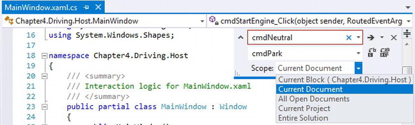
Figure 4-39. Find and Replace in Visual Studio 2012
- Press Ctrl-F and do another Find and Replace for PutInNeutral and replace it with PutInPark.
- Add a new class to the WPF project by right-clicking the project and selecting Class. This file will hold the enum object for the possible transitions within the state machine workflow. Add the code from Listing 4-4 and rename the class file to EnumTransition.cs. Change the last enum of PutInNeutral to PutInPark.
- Add a new class to the workflow project by right-clicking the project and selecting Class. This file will hold the bookmark activity.
- Rename the new class file as WaitForResponse.cs and copy in the following code:
using System;
 using System.Collections.Generic;
 using System.Linq;
 using System.Text;
 using System.Activities;

 namespace Chapter4.StateMachine
 {
     public sealed class WaitForResponse<TResult> : NativeActivity<TResult>
     {
      public WaitForResponse()
             : base()
         {

         }

         public string ResponseName { get; set; }

         protected override bool CanInduceIdle
         { //override when the custom activity is allowed to make he workflow go idle
             get
             {
                 return true;
             }
         }

         protected override void Execute(NativeActivityContext context)
         {
             context.CreateBookmark(this.ResponseName, new BookmarkCallback(this.ReceivedResponse));
         }

         void ReceivedResponse(NativeActivityContext context, Bookmark bookmark, object obj)
         {
             this.Result.Set(context, (TResult)obj);
         }
     }
} - Compile the workflow project so the WaitForResponse compiles and can later be used from the activity toolbox.
- Rename the default workflow file of Activity1.xaml to wfDriving.xaml. At this point you are ready to start building the workflow.
- Hover over the Toolbox tab if it is not already pinned to within the designer. Drag and drop a new StateMachine activity onto the designer fabric for the workflow.
- Drag and drop three new states and one FinalState onto the workflow, so the one that was already included by default should make a total of five.
- Rename the State1 that was included by default to In Park. Rename the other states to Engine Running, In Reverse, and In Drive. Rename the FinalState as Turned Off. At this point, it does not matter how the states are organized within the designer fabric. After the transitions are added, they can be reorganized so that the transitions are not spread so far apart.
- Add a transition from the Engine Running state to the Turned Off state by hovering over the Engine Running state until a transition node appears on the edge of the state. Click on the node to drag a new transition from the state to the Turned Off state. Click on the new transition and within the Properties window, change the DisplayName property to Stop Engine. A transition can also be added automatically by dragging one state close to another state and dropping it on one of the arrows that appears around the state’s edges.
- Follow the same directions from the step above and add another transition from the In Park state to the Engine Running state and change its DisplayName property to Start Engine.
- Add another transition from the In Drive state to the In Park state and change its DisplayName property to Put In Park.
- Add another transition from the In Drive state to the In Reverse state and change its DisplayName property to Put In Reverse.
- Add another transition from the In Reverse state to the In Park state and change its DisplayName property to Put In Park.
- Add another transition from the Engine Running state to the In Drive state and change its DisplayName property to Put In Drive.
- Add another transition from the Engine Running state to the In Drive state and change its DisplayName property to Put In Reverse.
- Add one last transition from the In Reverse state to the In Drive state and change its DisplayName property to Put In Drive. At this point the workflow’s states and transitions should follow the same flows as indicated in Figure 4-40. There are probably a couple of design time errors but the next couple of steps will clear those up as the bookmark activities are added for each transition.
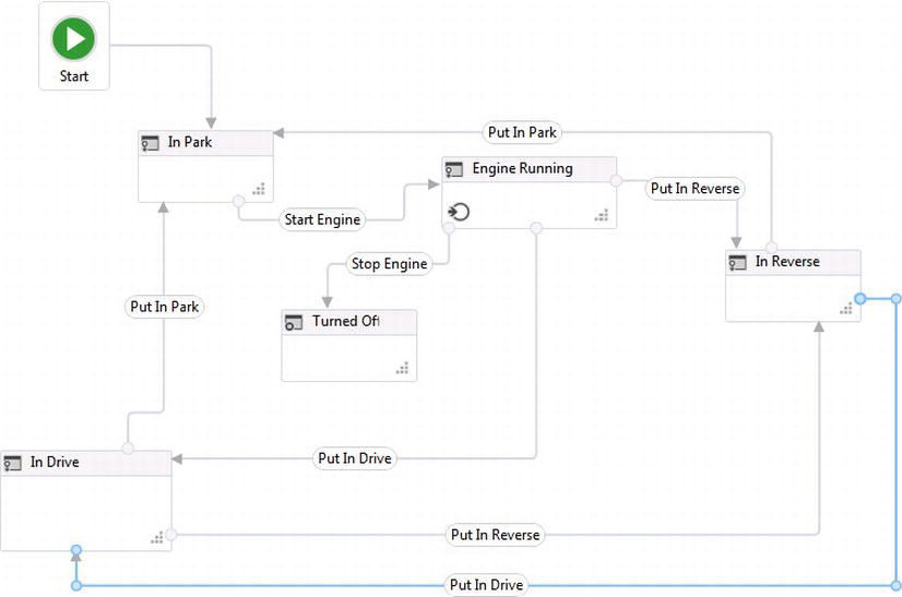
Figure 4-40. Completed states and transitions
- Double-click the transition named Put In Drive from the state In Reverse to the In Drive state. Drag the WaitForResponse activity from the Chapter4.StateMachine section of the toolbox and drop it into the trigger of the transition. Select String as the TResult value for the bookmark that will passed to the workflow; however values will not be passed into the workflow in this lab.
- While the WaitForResponse activity is selected, change the property of ResponseName within the Properties window to InGear.
- Double-click the transition named Put In Reverse from the state In Drive to the In Reverse state, and add another WaitForResponse activity using String as the TResult value. Change the ResponseName property to PutInReverse.
- Double-click the transition named Put In Drive from the state Engine Running to the In Drive state, and add another WaitForResponse activity using String as the TResult value. Change the ResponseName property to InGear.
- Double-click the transition named Put In Park from the state In Drive to the In Park state, and add another WaitForResponse activity using String as the TResult value. Change the ResponseName property to Put In Park.
- Double-click the transition named Put In Park from the state In Reverse to the In Park state, and add another WaitForResponse activity using String as the TResult value. Change the ResponseName property to PutInPark.
- Double-click the transition named Put In Reverse from the state Engine Running to the In Reverse state, and add another WaitForResponse activity using String as the TResult value. Change the ResponseName property to PutInReverse.
- Double-click the transition named Stop Engine from the state Engine Running to the Turned Off state, and add another WaitForResponse activity using String as the TResult value. Change the ResponseName property to TurnOff.
- Finally, double-click the transition named Start Engine from the state In Park to the Engine Running state. This time add an If activity within the trigger, and then add a WaitForResponse activity using String as the TResult value. Change the ResponseName property to StartEngine.
- Click on the Variables tab at the bottom of the workflow designer and add a new variable named varEngineStarted with a variable type of Boolean and a default value of false. Set the scope for the variable to StateMachine.
- Add the variable name varEngineStarted within the condition of the If activity. If the engine is already started, the bookmark will not be needed. If not, then a manual event using the bookmark will indicate when the engine starts. See Figure 4-41.

Figure 4-41. Engine started condition
- Double-click the Engine Running state and add an Entry action. Drag and drop an Assign activity and set the To property of the activity to varEngineStarted and the Value property to true. Make sure that Chapter4.Driving.Host is set as the startup project and then press F5 to run the solution.
After the solution compiles, the WPF application hosting the workflow should appear (see Figure 4-42).
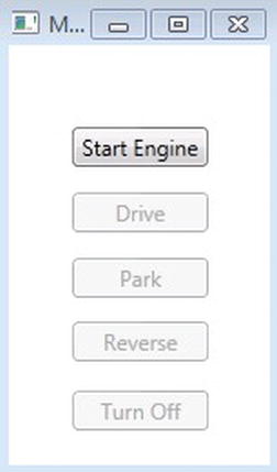
Figure 4-42. Starting the workflow
Pressing the Start Engine button will allow the state to transition over to Engine Running, where the buttons for Reverse, Turn Off, and Drive appear, as shown in Figure 4-43.
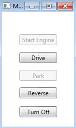
Figure 4-43. Engine started
Selecting the Drive button cycles the buttons again, making Park and Reverse available, as shown in Figure 4-44.
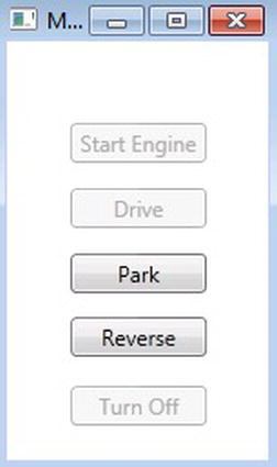
Figure 4-44. Automobile in Drive
This time, go into the workflow and add a breakpoint on the Engine Running state. This is a new feature in WF4.5 for adding breakpoints on states, but you will notice that the buttons clearly show that the state can only be changed to Park and Reverse while In Drive (see Figure 4-45).

Figure 4-45. Auto-transitioning to Engine Running from In Park
Pressing the Park button transitions the workflow back to In Park but because you set the variable indicating that the automobile is running, the breakpoint in Figure 4-44 catches the transition being made automatically from the In Park state to the Engine Running state. While the automobile is running, it can finally be turned off, which will gray out all the buttons, indicating that the workflow has completed (See Figure 4-46).
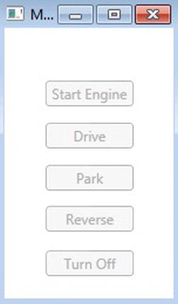
Figure 4-46. Driving workflow completed
Summary
This chapter focused on the components for building state machine workflows within WF4.5 and provided steps for how they can used to implement state machine workflows within applications. State machine workflows are an important type of workflow for implementing workflows within WF and one that models human behavior. State machine workflows model states and human events that are required for a business process to be executed. The majority of the workflows built for modeling long-running business processes can take advantage of state machine workflows, but I also demonstrated that applications can have their UI functionality driven by workflows as well.
State machines are made up of predefined states within a process that are connected through transitions and defining states. Wiring up transitions has been simplified in the latest release in WF4.5, so state machine workflows can be implemented very quickly. State machine workflows can be built without worrying about how to combine them with flowchart and sequential workflows.
This chapter covered the important functionality for building and executing state machine workflows. Tracking was not covered, however, so I want to mention two new classes that are included for tracking information on state machine activities:
- StateMachineStateQuery
- StateMachineStateRecord
Although tracking state machine workflows was not covered in this chapter, Chapter 10 is dedicated to tracking workflows; it will demonstrate how to track the different types of workflows in WF, including state machines. The next chapter, Chapter 5, will show you how to build a different type of flow control called a Flowchart, which is used for modeling decisions within workflows.