20 Real-Time Operating Systems
Acronym
| AC | Advisory Circular |
| AFDX | ARINC 664 avionics full-duplexed switched ethernet |
| APEX | APplication EXecutive |
| API | application program interface |
| BSP | board support package |
| CAN | controller area network |
| CEO | chief executive officer |
| COTS | commercial off-the-shelf |
| CPU | central processing unit |
| EAL | evaluation assurance levels |
| EPROM | erasable programmable read-only memory |
| FAA | Federal Aviation Administration |
| IEEE | Institute of Electrical and Electronic Engineers |
| IMA | integrated modular avionics |
| I/O | input/output |
| ISR | interrupt service routine |
| MMU | memory management unit |
| MOS | module operating system |
| POS | partition operating system |
| POSIX | portable operating system interface |
| RAM | random access memory |
| RSC | reusable software component |
| RTOS | real-time operating system |
| SAP | support access port |
| SVA | software vulnerability analysis |
| UNIX | uniplexed information and computing system |
| VMM | virtual machine monitor |
20.1 Introduction
Since the arrival of the new millennium, the real-time operating system (RTOS) has become a common component in aviation systems. This chapter explains what an RTOS is, why it is used, how it fits into the typical avionics system, desired RTOS functionality, issues to be addressed when using an RTOS, and some future RTOS-related challenges.
20.2 What Is an RTOS?
H.M. Deitel writes:
Operating systems are primarily resource managers; the main resource they manage is computer hardware in the form of processors, storage, input/output (I/O) devices, communication devices, and data. Operating systems perform many functions such as implementing the user interface, sharing hardware among users, allowing users to share data among themselves, preventing users from interfering with one another, scheduling resources among users, facilitating I/O, recovering from errors, accounting for resource usage, facilitating parallel operations, organizing data for secure and rapid access, and handling network communications [1].
In general, an operating system is software that manages the hardware resources of a computer, providing controlled access for one or more applications running on the computer. A general-purpose RTOS performs these operations but is also specially designed to run applications with very precise timing. Safety-critical RTOSs are a subset of the general-purpose RTOS and tend to have the following characteristics: deterministic (predictable), responsive (in a guaranteed timeframe), controllable (by the software developer and integrator), reliable, and fail-safe [2]. These characteristics will be further discussed when considering the desirable features of a safety-critical RTOS.
The following terms are used in this chapter and in RTOS literature:*
Application: Software which consists of tasks or processes that perform a specified function on the aircraft. An application may contain one or more partitions [3].
Application Program Interface (API): A formal set of software calls and routines that can be referenced by an application program in order to access supporting system or network services.
Partition: “A program, including instruction code and data, that is loadable into a single address space in a core module” [3]. The RTOS has control over each partition’s use of computer resources (processing time, memory, and other resources) in order to isolate each partition from all others that share the core processing hardware.
Interpartition: Communication between partitions.
Robust Partitioning: “A mechanism for assuring the intended isolation of independent aircraft operational functions residing in shared computing resources in all circumstances, including hardware and programming errors. The objective of robust partitioning is to provide the same level of functional isolation as a federated implementation (i.e., applications individually residing on separate computing elements). This means robust partitioning must support the cooperative coexistence of applications on a core processor, while assuring unauthorized, or unintended interference is prevented” [3].
20.3 Why Use an RTOS?
The RTOS is the heart of many modern avionics systems. An RTOS can impact software dependability, productivity, and maintainability [4]. Using an API, the RTOS provides a clearly defined and controlled interface between the application and the underlying hardware. Additionally, an RTOS narrows the possible interactions, making it easier to verify correctness of the applications. Without an RTOS, the programmer needs detailed knowledge of the underlying hardware and its functionality.
In the past, the software in embedded systems was written as a monolithic set of code and was tightly coupled to the underlying hardware. This was necessary to ensure that the performance requirements were met. Unfortunately, this type of design made the software difficult to maintain, reuse, and port to different hardware.
By abstracting and encapsulating the hardware interface, an RTOS largely eliminates the need for the application developer to write hardware-specific code. The RTOS improves portability and
screens the complexities of the computer from the programmer, leaving him to concentrate on the job at hand. Detailed knowledge of interrupts, timers, analogue-to-digital converters, etc. is no longer needed. As a result the computer can be treated as a virtual machine, providing facilities for safe, correct, efficient, and timely operation. In other words, it makes life easy (or at least easier) [4].
Another driver of increased RTOS usage has been the microprocessor’s increased capability. With the speed and capacity of today’s processors, it is now possible to run multiple applications on a single processor. Additionally, since weight reduction saves cost over the life of an aircraft, there is a great desire to minimize hardware on the aircraft. In order to maximize the benefits of the processor, minimize weight on the aircraft, and improve maintenance, integrated modular avionics (IMA) systems are replacing many of the traditional federated systems. An IMA allows multiple applications to run on a single processor.
To enable IMA, robust partitioning between the applications is needed. A robustly partitioned RTOS ensures the following [6]:
The execution of an application does not interfere with the execution of any other application.
Dedicated computer resources allocated to applications do not conflict or lead to memory, schedule, or interrupt clashes.
Shared computer resources are allocated to applications in a way that maintains the integrity of the resources and the separation of the applications.
Resources are allocated to each application independently of the presence or absence of other applications.
Standardized interfaces to applications are provided.
Software applications and the hardware resources needed to host them are independent.
IMA implementation hinges on the robustly partitioned RTOS and its environment. Chapter 21 discusses partitioning in more detail.
The competitiveness of the aviation market has also made the use of commercial off-the-shelf (COTS) RTOSs appealing. Use of a COTS RTOS largely eliminates the need for system developers to develop their own RTOS and maintain operating system development as a core competency. A DO-178C (or DO-178B) compliant COTS operating system is quite expensive, but can be more cost effective than building an RTOS from scratch, maturing it to support safety needs, developing it to meet DO-178C, and maintaining it. Some of the common issues with COTS RTOSs are discussed later in this chapter.
20.4 RTOS Kernel and Its Supporting Software
Figure 20.1 illustrates the typical place of the RTOS in an avionics system. The applications software may be in one or multiple partitions. Both partitioned and nonpartitioned RTOSs are used in safety-critical systems. The partitioned RTOSs are becoming more common in aviation projects. Since the RTOS kernel and its supporting software are part of the embedded system, they need to meet DO-178C (or DO-178B).* Figure 20.1 shows that the RTOS kernel is supported by several components, including libraries, board support package (BSP), device drivers, and an API. The RTOS kernel and each of the main supporting components are briefly described in the following subsections.
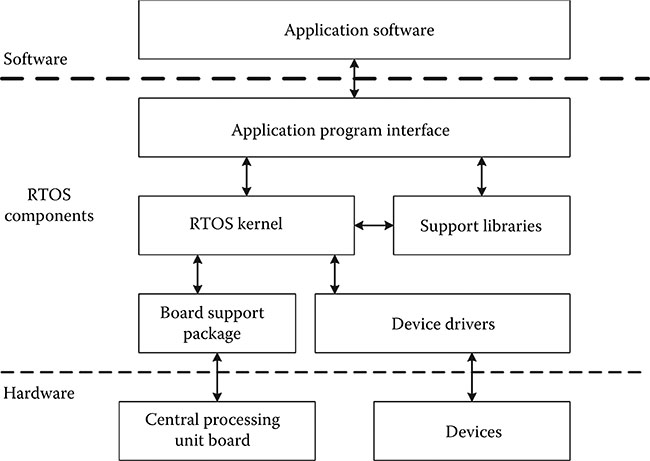
Figure 20.1 Typical RTOS components and relationship to applications.
20.4.1 RTOS Kernel
The kernel is the heart of the RTOS. It provides the basic services (such as the ARINC 653 services described in Section 20.8.1) and is designed to be independent of the underlying hardware, as much as possible.† The goal of most RTOS developers is to isolate the kernel from the hardware in order to allow reuse and portability. The hardware-specific code is normally implemented in the BSP and device drivers.
20.4.2 Application Program Interface
The applications access the RTOS services through an API, which functions as the interface between the RTOS kernel and an application.
The API provides a list of available calls that a programmer can make using the RTOS. The ARINC 653 APEX (APplication EXecutive) is the most common API used in avionics for IMA systems. The POSIX (portable operating system interface) is also employed by some RTOSs. POSIX standards (such as Institute of Electrical and Electronic Engineers [IEEE] 1003.1b) include the following interface definitions for an RTOS: task management, asynchronous I/O, semaphores, message queues, memory management, queued signals, scheduling, clocks, and timers [7]. POSIX is based on UNIX (uniplexed information and computing system). Because there were multiple flavors of UNIX, there are several IEEE standards related to POSIX [4]. As UNIX was not developed for a hard real-time environment, POSIX must be used carefully in avionics. This was one of the motivations for the development of the ARINC 653 APEX. There is some similarity between ARINC 653 and POSIX, since many of the POSIX concepts influenced ARINC 653. The difference between POSIX and ARINC 653 APEX is small at the API level; however, the differences are more significant at the program organization level. APEX was conceived to provide separation between different applications sharing the same processor; i.e., to provide robust partitioning between the APEX partitions. POSIX does not provide the same kind of robust partitioning, but it does provide support for multiple processes to collaborate. Table 20.1 provides a high-level general comparison of ARINC 653 and POSIX.
20.4.3 Board Support Package
The BSP isolates the RTOS from the target computer processing hardware. It allows the RTOS kernel to be portable to various hardware architectures within the same central processing unit (CPU) family. “The BSP initializes the processor, devices, and memory; performs various memory checks; and so on. Once initialization is complete, the BSP can still function to perform low-level cache manipulations” [9], as well as some other hardware access (e.g., flash manipulation or timer access). Much of the BSP code operates in privileged mode and works closely with the RTOS. The BSP is sometimes called a hardware abstraction layer, a hardware interface system, or platform enabling software. It is customized for the specific hardware and is often implemented using C and assembly. The BSP is sometimes developed by the RTOS users (e.g., the avionics developer) using a template from the RTOS supplier—especially when the avionics utilize custom hardware. At other times, the BSP is provided and/or tailored by the RTOS supplier. Depending on the nature of the hardware, the BSP can be a rather large component.
20.4.4 Device Driver
Similar to the BSP, the device driver provides the interface between the RTOS kernel and a hardware device. The hardware devices may be on the processor board or separate. Hardware on the processor board may be handled by the BSP or a separate driver. The driver is a low-level, hardware-dependent software module that provides the interface between an application (sometimes mediated by higher level RTOS library or kernel functions) and a specific hardware device. A device driver is responsible for accessing the hardware registers of the device and may include an interrupt handler to service interrupts generated by the device. Most avionics systems have multiple devices, such as Ethernet devices, ARINC 664 avionics full-duplexed switched ethernet (AFDX) end systems, RS-232 serial devices, I/O ports, analog-to-digital converters, and controller area network (CAN) databuses.
Table 20.1 Basic Comparison of POSIX and ARINC 653 Features

20.4.5 Support Libraries
Oftentimes, language-specific run-time support is provided as libraries with the RTOS kernel. For example, “in the C language, a number of standard library specifications permit the user to call functions to move memory, compare strings, and use mathematical functions such as mod, floor, and cos” [9]. These run-time libraries are often packaged with the RTOS (either within the kernel or as a separate library package). The libraries are normally provided by the RTOS supplier as precompiled object code that can be linked together with the applications. That way, only the library functions needed are linked in. Some smart linkers can actually identify which library functions are called by the application and only link those functions into the executable.
20.5 Characteristics of an RTOS Used in Safety-Critical Systems
This section identifies the key characteristics of safety-critical RTOSs used in the aviation domain.
20.5.1 Deterministic
A safety-critical system delivers the right answer in the right order and at the right time. “Determinism is the characteristic of a system which allows the correct prediction of its future behavior given its current state and knowledge of future changes to its environment (inputs)” [10]. Nondeterminism on the other hand “means that a systems’ future behavior cannot be correctly predicted. (An unpredictable system cannot be called ‘safe.’)” [10]. The behavior of an RTOS in a safety-critical domain must be predictable. That is, given a particular input, the RTOS generates the same output. In particular, the outputs are within the bounds defined in the requirements. A deterministic RTOS provides both functional correctness and temporal correctness as defined by the requirements; it also only consumes known and expected (bounded) amounts of memory and time.
20.5.2 Reliable Performance
The RTOS must meet the horsepower requirements needed to enable the application to perform its intended functionality. Many factors determine the RTOS performance, including computation times, scheduling techniques, interrupt handling, context switch times, cache management, task dispatching, etc. [4]. Performance benchmarks are typically provided in a data sheet with the RTOS. Performance varies widely depending on the specific hardware, interfaces, clock speed, compiler, design, and operating environment. Thus, when selecting an RTOS, companies almost always run their own benchmarks before deciding which RTOS to purchase.
20.5.3 Compatible with the Hardware
The RTOS kernel must be compatible with the selected processor. Likewise, the BSP must be compatible with the selected processor board and core devices, and the device drivers must be compatible with the system devices.
20.5.4 Compatible with the Environment
The RTOS should be capable of supporting the selected programming language and compiler. Most RTOSs are supported with an integrated development environment, which includes the compiler, linker, debugger, and other tools for successful integration of the applications, RTOS, supporting software, and the hardware.
20.5.5 Fault Tolerant
Fault tolerance is “the built-in capability of a system to provide continued execution in the presence of a limited number of hardware or software faults” [11]. A fault tolerant RTOS plans for application failures and provides mechanisms for recovery or shutdown. The RTOS enables fault management which consists of (1) detecting faults, failures, and errors; (2) correctly identifying faults, failures, and errors when they are detected; and (3) performing the response preplanned for the system [11].
20.5.6 Health Monitoring
Health monitoring is closely related to fault management and is another feature of a fault tolerant RTOS. Health monitoring is a service frequently provided by an RTOS to provide fault management for most (if not all) of the system that uses the RTOS. DO-297 explains that health monitoring is responsible for detecting, isolating, containing, and reporting failures that could adversely affect resources or the applications using those resources [11]. DO-297 focuses on the IMA platform; however, the RTOS plays a key role in the overall health management scheme of the system. The Federal Aviation Administration (FAA) research report on RTOSs in IMA systems states the following:
Health monitoring is specified in ARINC 653. The health monitor is the RTOS function responsible for identifying, responding to, and reporting hardware, application, and RTOS faults and failures. Health monitoring helps to isolate faults and prevents failures from propagating.
By classifying and categorizing faults and the health management responses, a range of possibilities exists that helps the application supplier and IMA system integrator select appropriate behavior. Configuration tables are used to describe intended recovery of identified faults, such as ignoring the fault, reinitializing a process, restarting (warm or cold) a partition, performing a total system reset, or calling a system-specified routine to take system-specified actions [12].
ARINC 653 identifies a number of error codes that must be detected and handled. “An error can be handled within a process, in a partition, or in the health monitoring module or process” [9].
The objective of the ARINC 653 health monitoring function is to
contain faults before they propagate across an interface boundary. In addition to self-monitoring techniques, application violations, communication failures and faults detected by applications are reported to the RTOS. A recovery table of faults is used to specify the action to be taken in response to the particular fault. This action [is] initiated by the Health Monitor and might include terminating an application and starting an alternative application, together with an appropriate level of reporting [13].*
The recovery action is dependent on the system design and requirements.
20.5.7 Certifiable
Certifiability is a necessary characteristic of an RTOS utilized by safetycritical systems. If the RTOS is to be installed in an aircraft, it will need to satisfy the objectives of DO-178C.† It is worth noting that the RTOS itself is not certified; rather, it is developed to be certified as part of an aircraft, engine, or propeller.‡ Most COTS RTOSs suitable for installation in aviation products have a certification package available to support the overall certification. The certification package contains the artifacts to show compliance with DO-178C (or DO-178B) and to support safety and certification. Some of the typical certification challenges for RTOSs are presented later in this chapter (Section 20.7).
20.5.8 Maintainable
Maintainability is a desirable characteristic for all software used in safetycritical systems, including the RTOS. Since the life of the system is likely to be quite long (possibly over 20 years), the RTOS must be maintainable (i.e., able to be modified to accommodate additional applications, equipment, hardware, etc.). The life cycle data and configuration management processes required by DO-178C support maintainability.
20.5.9 Reusable
While not a required characteristic, most RTOSs are designed to be reusable. As noted previously, the kernel is abstracted from the hardware using a BSP and device drivers. The FAA’s Advisory Circular (AC) 20-148, entitled Reusable Software Components, is typically applied to an RTOS. AC 20-148 provides FAA guidance for packaging a reusable software component (RSC) for reuse in multiple systems. Even if the project does not seek an RSC letter from the FAA, they will probably want to follow the suggestions of the AC in order to develop the RTOS component to be as reusable as possible. Reuse is further discussed in Chapter 24.
20.6 Features of an RTOS Used in Safety-Critical Systems
This section identifies the key features of most safety-critical RTOSs used in the aviation domain. These features are closely related to the characteristics noted earlier and provide the means to implement those characteristics. The features most pertinent from a safety perspective are discussed.
20.6.1 Multitasking
Multitasking is a method where multiple tasks, also known as processes, share a common processor. Multitasking creates the appearance that many tasks are running concurrently on a processor when, in fact, the kernel interleaves (for a single core processor) their execution using a scheduling algorithm. When the processor stops executing one task and starts executing another task, this is called a context switch. When context switches occur frequently enough, it appears that tasks are running in parallel. Each seemingly independent program (task) has its own context, which is the processor environment and system resources that the task sees each time it is scheduled to run by the kernel.
20.6.2 Guaranteed and Deterministic Schedulability
Meeting deadlines is one of the most fundamental requirements of an RTOS. For safety-critical systems, the scheduling and timely completion of multiple tasks must be deterministic. For RTOSs used in advanced avionics (e.g., IMA systems), two kinds of schedulability are normally desired:* (1) scheduling between partitions and (2) scheduling within partitions. Each is discussed here.
20.6.2.1 Scheduling between Partitions
The ARINC 653 model requires a round-robin execution sequence between partitions. This establishes a time frame called the major time frame. Time slots of fixed duration are defined within the major time frame. However, the duration of each time slot does not need to be the same. A configuration table defines which partitions will execute in which time slot within a frame:
A partition may be allocated to more than one slot within a frame. Execution of each partition follows in sequence, starting at the beginning of a frame. When the last partition in the frame is executed, the sequence is repeated. The time slots are strictly enforced by the MOS [Module Operating System]. A clock device is used to ensure the timely switching between partitions [9].†
20.6.2.2 Scheduling within Partitions
Many types of scheduling schemes can exist within a partition. Most RTOSs do their scheduling using priorities and preemption. Each task is assigned a priority. A higher priority task is executed before all tasks with lower priority. Preemptive means that as soon as a higher priority task is ready to run, it can stop the execution of a lower priority task that is currently executing. It’s similar to when you’re in a meeting with the boss. If the chief executive officer (CEO) of the company comes by, your discussion with your boss is preempted until he or she is finished with the higher priority discussion with the CEO. The following list summarizes the most common scheduling approaches used in safety-critical RTOSs. There is a plethora of literature available on each of these processes; only a brief synopsis is discussed here:‡
Cyclic executive. This technique cycles through a set of processes whose execution order has been predetermined. It is a common approach even when an RTOS is not used.
Round-robin. The name of the algorithm comes from the round-robin principle, where each person has an equal share of something. I once made it to the 4-H showmanship round-robin competition. Each competitor was given an equal time to show a horse, a steer, a pig, and a lamb. You’ll be pleased to know that I earned the Reserved Grand Champion trophy. The round-robin scheduling algorithm is one of the simplest scheduling algorithms for sharing time on a processor. A minor time slice is defined by the system, and all processes are kept in a circular queue. The scheduler goes around the queue, allocating processor resources to each process for a time slice interval. As new processes arrive, they are added to the tail of the queue. The scheduler functions by selecting the first process from the queue, setting a timer to interrupt after one time slice, and then dispatching the process. If the process is not finished at the end of the time slice, it is preempted and added to the tail of the queue. If the process does finish before the end of the time slice, it releases the processor. A context switch occurs every time a process is granted access to the processor. The context switching adds overhead to the process execution time [9].
Fixed priority preemptive scheduling. Each task has a fixed priority that does not change. With fixed priority preemptive scheduling, the scheduler ensures that at any given time the highest priority task is executed out of all the tasks that are currently ready to execute. This approach uses an interrupt to preempt a lower priority task if a higher priority task becomes ready. The advantage of this approach is that it ensures that lower priority tasks don’t monopolize the processor time. However, the negative aspect is that it can block a lower priority task from executing indefinitely. Many RTOSs support this scheduling scheme.
Rate monotonic scheduling. The rate monotonic scheduling algorithm is considered the optimal static priority algorithm. It is a priority preemptive algorithm that assigns fixed priorities to tasks in order to maximize schedulability and to ensure that all deadlines are met. Each task is assigned a priority according to its period. The shorter the period (higher frequency), the higher the priority. This scheduling algorithm is implemented in several of the COTS RTOSs for safety-critical systems.
Deadline monotonic scheduling. The deadline monotonic scheduling algorithm is similar to rate monotonic scheduling, except the priority is assigned to the task with the shortest deadline, rather than the shortest period. Thus, the process with the shortest deadline is assigned the highest priority and the process with longest deadline gets the lowest priority.
Earliest deadline first scheduling. This is a dynamic priority preemptive policy. It places tasks in a priority queue, so that whenever a task finishes, the queue is searched for the process closest to its deadline.* This process becomes the next task scheduled for execution. Basically, the scheduler selects the process that has the earliest deadline to run first, which preempts any processes with a later deadline.
Least slack scheduling (also known as least laxity first scheduling). As with earliest deadline first approach, this is a dynamic priority preemptive policy. The priority is assigned based on the slack time (the remaining time to deadline minus the remaining execution time, which can be difficult to precisely predict). Slack time might also be described as the difference between the time until a task’s completion deadline and its remaining process time requirement. The process with the smallest slack preempts processes with larger slack.
20.6.3 Deterministic Intertask Communication
Since only one task can be run at a time (for single core processor), there must be mechanisms for tasks to communicate with one another. For many RTOSs, queues and messages provide a means for intertask communication; this approach helps to avoid the situation where a task reads a segment of memory while another is writing to it. There are at least three reasons that intertask communication is needed [4]:
To synchronize or coordinate activities without data transfer. Generally such tasks are linked by events, including time-related factors, such as time delays or elapsed time. Task synchronization or task cooperation is used to synchronize the shared resources. There is some overlap between task synchronization and task coordination because task synchronized operations may be used to coordinate tasking operations. However, as soon as an interrupt is used to block and release tasks, it is no longer task coordination because the tasks are synchronized with the real-time interrupts.
To exchange data without synchronizing. There are times when tasks exchange information without the need for synchronization or coordination. This is often accomplished with a data store (e.g., pools or buffers) that incorporates mutual exclusion to ensure data are not corrupted.
To exchange data at carefully synchronized times. This is the scenario where tasks wait for events and use data associated with those events. For example, task synchronization may be achieved by suspending or halting tasks until the required conditions are met.
20.6.4 Reliable Memory Management
RTOSs support memory allocation and memory mapping and take action when a task uses memory. Most processors include an on-chip memory management unit (MMU) that allows software threads to run in hardwareprotected address space [14]. The MMU is responsible for handling accesses to memory. MMU functionality typically includes virtual addresses to physical addresses translation, memory protection, cache control, and bus arbitration. Since the MMU is COTS functionality provided with the processor and the integrity of the MMU is unknown, the MMU typically requires some special attention during the certification effort. Generally, the accuracy of the MMU’s functionality, as well as the overall processor functionality, is verified through the detailed testing of the RTOS and its supporting software (e.g., BSP). Some of the common memory issues (such as memory leakage, fragmented memory, and memory coherency) to avoid are discussed later.
20.6.5 Interrupt Processing
Real-time systems usually respond to external events using interrupts through interrupt service routines (ISRs). The RTOS normally saves the context of the interrupted task to return after the interrupt is processed. The interrupt processing can have a significant impact on the system performance. Generally, interrupt processing does the following [15]:
Suspends the active task.
Saves the task-related data that will be needed when resuming the task.
Transfers control to the appropriate ISR.
Performs some processing in the ISR to determine necessary action.
Retrieves and saves critical (incoming) data associated with the interrupt.
Sets required device-specific (output) values.
Clears the interrupt hardware so the next interrupt can be recognized.
Transfers control to the next task, as determined by the scheduler.
In order to prevent race conditions (two tasks attempting to change the same data without coordination), RTOSs sometimes disable interrupts while accessing or manipulating internal (critical) operating system data structures. The maximum time that an RTOS disables interrupts is referred to as the interrupt latency. Worst-case interrupt latency times should include “all software overhead that must be endured before the actual ISR is executed” [16]. There is typically a trade-off between interrupt latency, throughput, and processor utilization.* This should be factored in when determining worstcase performance [17]. A key to meeting performance is to have low interrupt latency [18].
Some RTOSs reduce interrupt latency through a technique called work deferral. If an ISR causes other RTOS work to be scheduled during an interrupt, the work may be saved on a work queue and invoked later. This reduces the times of critical regions and makes the system more responsive; however, it adds complexity when calculating the worst-case execution time.
20.6.6 Hook Functions
Many RTOSs include what is referred to as hook functions (or callback functions). A hook function allows a developer to associate application code to a particular function within the RTOS. The hook is executed by the RTOS function (sometimes with elevated priority and access to RTOS resources). These hooks can be used to extend the RTOS for specific user needs, particularly if the proprietary RTOS source code is not available. Hook functions allow customization without modifying the RTOS source code and inadvertently introducing a defect. Hook functions can allow the RTOS user to perform some actions before or after the RTOS responds to some event without the overhead of a separate task creation. Oftentimes, hook functions are used to assist with debugging during development. They may be deactivated or disabled in the final product. Obviously, hook functions must be handled carefully in safety-critical systems because they have the ability to modify the behavior of the RTOS itself [19].
20.6.7 Robustness Checking
An RTOS should be designed to protect itself against certain user errors. Examples of built-in robustness checks include validating parameters passed through the API by an application making a system call, ensuring that a task priority is within the permitted range of the RTOS, or ensuring that a semaphore operation works only on a semaphore object. Robustness checking is complex and verification of the robustness features may require special testing techniques [20].
20.6.8 File System
File system is a way of managing data storage.† Similar to the file system in a desktop environment, the RTOS file system manages and hides the details of the various forms of data storage on the hardware. The file system provides the ability to open, close, read, write, and delete files and directories.
The implementation is unique to the type of storage media (such as random access memory (RAM), flash memory, erasable programmable read-only memory (EPROM), or network-based media). The file system allows multiple partitions to access the storage media. The RTOS kernel or its supporting library implements the file system to manage the low-level details of the media for the partitions that use it. Avionics applications often use a file system to store and retrieve data. For example, flight management systems and terrain awareness systems may use a file system to access their databases [13].
20.6.9 Robust Partitioning
Many IMA RTOSs support robust partitioning. The definition of robust partitioning was included earlier (in Section 20.2). DO-297 section 2.3.3 explains the following:
The objective of robust partitioning is to provide an equivalent level of functional isolation and independence as a federated system implementation (i.e., applications individually residing on separate Line Replaceable Units (LRU)). This means robust partitioning supports the cooperative coexistence of applications using shared resources, while assuring that any attempted unauthorized or unintended interaction is detected and mitigated. The platform robust partitioning protection mechanisms are independent of any hosted applications, that is, applications can not alter the partitioning protection provided by the platform [11].
The RTOS plays a key role in implementing the robust partitioning—to ensure that the shared resources of time, memory, and I/O are protected. Partitioning is described in more detail in Chapter 21.
20.7 RTOS Issues to Consider
This section summarizes technical and certification issues that often require consideration when developing an RTOS and when implementing it for a safety-critical system. Some issues were noted earlier but are further elaborated here. This is not an exhaustive list of issues that may be encountered on a program but is some of the ones that have traditionally arisen and that are generally most pertinent to safety.
20.7.1 Technical Issues to Consider
20.7.1.1 Resource Contention
As the name implies, resource contention is a conflict over a shared resource, such as processor or memory. Three specific contentions that need to be dealt with in an RTOS are deadlock, starvation, and lockout. Each is described in the following:
Deadlock is a condition where no processes will be completed because they cannot access the resources they require to make progress. The following conditions must be true for a deadlock to occur: (1) mutual exclusion (resources may only be allocated to one process at a time), (2) hold and wait (a process may allocate a resource and wait for others), (3) no preemption (a resource may not be forcibly taken away), and (4) circular wait (processes are holding resources that other processes need). Deadlock is almost impossible to find by testing, but may be found by analysis (formal methods can help with this). Deadlock is typically avoided through design [7] by preventing one of the four conditions in the RTOS architecture [21].
Starvation occurs “when a task does not receive sufficient resources to complete processing in its allocated time” because other tasks are using the needed resources [22].
Lockout is a special condition of starvation where a task is locked out because another task is blocked before returning a shared resource [7].
20.7.1.2 Priority Inversion
Priority inversion is a type of deadlock that occurs when a high priority task is forced to wait for the release of a shared resource owned by a lower priority task. “The period of time that a task has a lock on a shared resource is called the task’s critical section or critical region” [21]. A famous example of priority inversion is the Mars Pathfinder mission. A few days into the mission, the Pathfinder started to have persistent resets, causing loss of the system for long periods of time. Testing and analysis revealed that the problem was caused by priority inversion. A low priority software task on the Pathfinder shared a resource with a high priority task. The low priority task blocked the shared resource after it was preempted by some medium priority tasks. “When another high priority task discovered the previous high priority task had not completed, it initiated a system reset” [5]. A global default setting in the RTOS allowed the priority inversion.
There are two approaches that are typically used to address the priority inversion issue: (1) priority inheritance protocol or (2) priority ceiling protocol. Some RTOSs provide both protocols and let the user decide the preferred algorithm [14]. Kyle and Bill Renwick cover the advantages and disadvantages of both protocols in their paper entitled How to use priority inheritance. They suggest that the “best strategy for solving priority inversion is to design the system so that inversion can’t occur” [23]. There is considerable literature available on priority inversion. This section only provided an introduction.
20.7.1.3 Memory Leaks
A memory leak is “an error in a program’s dynamic-store allocation logic that causes it to fail to reclaim discarded memory, leading to eventual collapse due to memory exhaustion” [24]. It is typically addressed by avoiding dynamic memory manipulation in safety-critical applications; this is accomplished by locking the memory allocation mechanism after initialization and disabling the freeing of memory.
20.7.1.4 Memory Fragmentation
Memory fragmentation occurs when memory is used inefficiently, leading to poor performance and possibly memory exhaustion. To avoid this, the memory allocation technique needs to be well defined, organized, and controlled. The following practices can help to avoid memory fragmentation: (1) fix the block size allocation, (2) partition and size the allocated memory, (3) use identifiers to track allocated memory, and (4) protect and isolate segments [4].
20.7.1.5 Intertask Interference
Intertask interference occurs when a task can modify the memory of another task or even the operating system itself. This is addressed by separating the RTOS from applications (e.g., using protected modes) and by utilizing the MMU facilities [4]. As noted earlier, memory protection is critical when implementing robust partitioning.
20.7.1.6 Jitter
The cache and pipeline features of a processor improve performance, but they also add uncertainty to task execution times. “This uncertainty is termed jitter, and is practically impossible to quantify analytically” [25]. Jitter depends on the hardware platform, operating system scheduling approach, and the tasks that share the processor. Selective flushing of the cache is a common solution to address cache jitter. The cache is flushed during the partition switch so that the incoming partition has a clear cache memory at the start of its duration. “Flushing means copying all the cache values only present in the cache back to main memory (i.e., they have been updated, and copy-back mode is used). This places the overhead at the start of the partition rather than it being distributed throughout” [9]. The amount of time to perform the flushing varies, depending on the number of values that need to be written to memory [9].
20.7.1.7 Vulnerabilities
Since the RTOS is typically developed separate from the applications that use it, it may have vulnerabilities that the users should note. A software vulnerability analysis is needed to identify the RTOS vulnerabilities and to mitigate them. Any vulnerabilities that are not mitigated by the RTOS design need to be identified for the systems integrator and/or the applications developers to address. Additionally, any assumptions or limitations on the RTOS users should be identified to ensure the RTOS is used properly. Some hazards may require special design or coding practices by the applications. “Other hazards may be mitigated by special analysis or verification technique undertaken during the subsequent states of the verification process” [20].
A software vulnerability analysis (SVA) can identify areas of potential anomalies, which can be provided as input not only to a robustness or stress-test plan, but also to a system functional hazard analysis or SSA [system safety assessment]. How an SVA is conducted is up to the RTOS developer or applicant [26].*
The SVA is based on a specific RTOS implementation. The FAA research report, Study of Commercial Off-The-Shelf (COTS) Real-Time Operating Systems (RTOS) in Aviation Applications, provides a table that can be used as the starting point for an SVA. The table identifies seven functional areas to consider: data consistency, dead or deactivated code, tasking, scheduling, memory and I/O device access, queuing, and interrupts and exceptions [26]. This table is included in Appendix B for convenience.
FAA AC 20-148 section 5.f explains that an RSC developer, such as an RTOS developer, needs to produce the following:
An analysis of the RSC’s behavior that could adversely affect the users’ implementation (for example, vulnerabilities, partitioning requirements, hardware failure effects, requirements for redundancy, data latency, and design constraints for correct RSC operation). The analysis may support the integrator’s or applicant’s safety analysis [27].
An SVA is comparable to a safety assessment of the RTOS functionality.† For a partitioned RTOS, the SVA is normally combined with the partitioning analysis, since many of the vulnerabilities are in the area of partitioning. However, the approach varies for each project; there isn’t a standardized packaging scheme for this analysis. Some RTOS developers package it as an SVA, some as a hazard analysis, and others as a partitioning analysis.
20.7.2 Certification Issues to Consider
This section identifies some of the common certification-related scenarios or issues that are encountered when using an RTOS in a safety-critical aviation system.
20.7.2.1 Creating a Safe Subset
Many of the current RTOSs used in safety-critical applications are based on a commercially available operating system with widespread usage and a proven track record for quality and performance. Most general-purpose RTOSs were developed with time-to-market as a priority rather than safety. In order to make the RTOS suitable for safety-critical applications, a new RTOS is created using a subset of the fully featured, general-purpose RTOS. Any functionality that might not be suitable for the safety-critical environment is removed or modified. Identifying the safety issues and removing or modifying them without impacting other RTOS functionality can be challenging and should be carried out with caution. This requires detailed knowledge of the RTOS design and code.
20.7.2.2 User’s Manual
Oftentimes, when a safe subset is created, the user’s manual is not updated to align with the RTOS subset. This could result in improper understanding or use of the RTOS.
20.7.2.3 Reverse Engineering
In order to comply with DO-178C (or DO-178B) the life cycle data for an RTOS is often reverse engineered from the source code. While doing this, issues with the source code itself may be identified. As will be discussed in Chapter 25, there are a number of issues to consider when reverse engineering.
20.7.2.4 Deactivated Features
Most RTOSs are designed to be used by multiple customers and have features that are not necessarily used or needed on every project. Some RTOSs are designed to be scalable, so the user can select and compile or link only the RTOS functions needed. Other RTOSs may have features that are available but not used. An RTOS built specifically for an application will have the advantage that only features used by the application will be present. Constructing an application-based subset may be difficult as the RTOS features are often interrelated. A more common approach is to define and verify an RTOS irrespective of the specific features used by each application and then to treat unused RTOS functionality as deactivated code. Chapter 17 provides a discussion of deactivated code and some of the things to consider when features are available in the RTOS but are not used by the applications.
20.7.2.5 Complexity
Some RTOSs are extremely complex, containing code with complex interactions and features that may not be needed. The complexity can make it difficult to prove the determinism and safety characteristics. Additionally, data coupling and control coupling analyses may be difficult if complexity is not managed. See Chapters 7 and 8 for design and coding practices to reduce complexity.
20.7.2.6 Disconnect with the System
Because the RTOS is developed separate from the system that will use it, there may be inconsistencies between the system needs and expectations and the RTOS functionality. Additionally, since the RTOS is part of the airborne software, it needs to link into the system or software requirements. The system which implements the RTOS must have requirements (typically software requirements) that trace or link to the RTOS requirements to ensure that the RTOS functionality supports the overall system needs, performs its intended functionality, and does not have any undesired or unused functionality.
20.7.2.7 Code Compliance Issues
If the RTOS was not originally developed for the safety-critical environment and DO-178C (or DO-178B) compliance, the code itself is often not up to the expected standards. In fact, the code may have been developed without any coding standards at all. Many times, the code for commercial RTOSs has limited comments and is so complex that even the original author may not be able to determine what was intended. Additionally, the code is generally written with complex data structures, nesting, and interconnectedness, making it difficult to verify.
20.7.2.8 Error Handling Issues
Error handling is an important feature in embedded systems. The RTOS is often employed to help with the error handling. Interestingly, error handling can account for a substantial portion of the RTOS code. Unfortunately, RTOS error handlers are prone to errors themselves; this is because they may not have been adequately verified since the conditions that activate them can be rare or esoteric. It is not uncommon to have faults reported at the lower levels but not be visible to the API; this may not be a problem with the error handler itself, but rather in code that is supposed to use the error handler.
20.7.2.9 Problem Reporting
Since many of the RTOSs are developed by organizations that are independent of the application developer or system integrator, the problem reports generated by the RTOS developer may not be available to the users (e.g., applications developers, system integrators, avionics manufacturers, or aircraft manufacturers). In the certification world all problem reports need to be visible to the aircraft applicant and confirmed that they don’t have a safety impact. This is an ongoing process. Some RTOS developers may not normally share problem reports throughout the life of the RTOS with their customers (this may be a business decision driven by fear that the product will look bad). When choosing to use a COTS RTOS, the user should ensure that problem reports are provided as problems are identified and for as long as the RTOS is on an aircraft.
20.7.2.10 Partitioning Analysis
As noted earlier, many RTOSs include support for robust partitioning. In order to prove the adequacy of the robust partitioning, a partitioning analysis is performed. The RTOS kernel is analyzed, as well as supporting components (such as BSP, device drivers, CPU, MMU, and device hardware), to confirm the adequacy of the partitioning. The partitioning analysis is like a safety analysis of the partitioning implementation. The analysis considers how partitioning violations could occur with shared time, space, and I/O resources; then mitigations are required for each vulnerability. In some projects, the partitioning analysis may be incomplete or inadequate to prove robust partitioning. Chapter 21 discusses partitioning analysis further.
20.7.2.11 Other Supporting Software
Frequently, much of the focus is on the RTOS kernel. However, libraries, BSPs, middleware, device drivers, etc. that connect the RTOS with the hardware or the applications also need to be considered. That is, they also need to comply with DO-178C, since they are part of the safety-critical system.
20.7.2.12 Target Testing
Many times, the RTOS is initially tested using a COTS BSP and COTS hardware. However, the RTOS must be tested with the actual hardware and supporting software that will be installed. This will normally require additional tests and modifications to some of the existing tests that were used with the COTS BSP and hardware. The target-based test not only is important to prove the functionality of the RTOS, BSP, and device drivers, it is also needed to verify that the COTS processor, MMU, etc. work as intended. A key selection criterion when choosing an RTOS is the availability of test suites and the anticipated level of rework necessary to reuse those tests for certification credit.
20.7.2.13 Modifications
While RTOS reuse is a goal, it is rarely fully realized. AC 20-148 provides guidance for RSCs. However, in reality most RTOSs are modified for each specific user. It is important to understand what is modified and what is not (i.e., a thorough change impact analysis is needed). Normally, it is recommended that the entire RTOS be retested when modifying for different users or when integrating with different hardware. Automated test suites tend to make this relatively straightforward.
20.8 Other RTOS-Related Topics
This section considers various topics related to RTOSs, including ARINC 653 overview, tool support, open source RTOSs, multicore processors, virtualization, and hypervisor technology.
20.8.1 ARINC 653 Overview
ARINC 653, Avionics Application Software Standard Interface, is a three-part standard that is about three inches thick when printed double-sided. Only a high-level overview is presented here. ARINC 653 specifies the APEX interface between applications and the underlying run-time system. It provides an API standard for a robustly partitioned operating system but allows flexibility for implementing the RTOS.
Paul Prisaznuk explains two key benefits of the ARINC 653 standard ized RTOS interface. First, it provides a clear interface boundary for the avionics software development. The avionics software applications and the underlying core software can be developed independently, allowing concurrent development of the RTOS and the applications that use the RTOS. Additionally, the same applications may be portable to other ARINC 653 compliant platforms. Second, the ARINC 653 RTOS interface definition enables the underlying core software and the hardware platform to evolve independent of the software applications that will be hosted on them [13].
The APEX API defines the following functionality for an RTOS: (1) sending and receiving data to/from other software applications or networked systems; (2) managing resources like time, memory, I/O, and displays; (3) handling errors; (4) managing files; and (5) scheduling software tasks or processes.
There are some unique things about the APEX API compared to other APIs. First, it is designed specifically for the aviation community with safety in mind. Second, it is designed for a partitioned computing environment. It includes two-tiered scheduling of applications (between partitions and within partitions) to ensure that one partition will not affect another partition. It also defines interpartition communications to allow safe communication between partitions. Third, it provides a health monitor interface that allows errors and conditions at the computing module level to be communicated to applications, as well as application level errors to be communicated and handled at the module (board) level [3]. Section 20.4.2 and Table 20.1 provide a high-level comparison of the ARINC 653 APEX features and the POSIX features.
In addition to the API, APEX provides a standardized, configurable operating environment for software applications to facilitate the abstraction of the application software from the underlying hardware. ARINC 653 defines the configuration specification and an assumed operating environment.
The basic concept of ARINC 653 is that an application is given a partition (like a container) to function in. The dimensions of the partition are defined by attributes such as memory size, processor utilization (e.g., in terms of period and duration), interpartition I/O ports and connections (communication channels), and health monitor actions. The attributes of the partition are determined by configuration data that are defined by the system integrator.
ARINC 653 contains three parts. Each part is briefly described in the following.
Part 1 defines the required services in order to meet safety needs, ensure application portability, and allow communication between partitions. Part 1 defines the following core services [3]:
Partition management: allows applications (even with different criticality levels) to execute on the same hardware with no undue influence on one another, spatially or temporally.
Process management and control: includes the resources needed to manage the processes within a single partition.
Time management: allows the management of one of the most critical resources controlled by the operating system (i.e., time). In the APEX philosophy, time is independent of process or partition execution. All time values are related to the core module time and are not relative to the partition or process.
Interpartition communication mechanisms: allow the communication of messages between two or more partitions executing either on the same hardware or on different hardware. Two paradigms are provided: queuing for variable-sized messages and sampling for fixedsize messages.
Intrapartition communication mechanisms: allow the communication of messages between processes within the same partition without the overhead needed for global message passing.
Health monitoring functions: monitors and reports platform and application faults and failures. It also helps isolate faults in order to prevent failures from propagating. In an IMA system the health monitor performs fault monitoring, fault containment, and fault management at both the application level and the system level.
Part 2 extends the Part 1 services to include the following [28]:
File system: a general-purpose, abstract method for managing data storage, as noted in Section 20.6.8.
Sampling port data structures: a standardized set of data structures for exchanging parametric data. These help to reduce unnecessary variability in parameter formats, thus reducing the need for custom I/O processing. These data structures also enable portability of applications and improve efficiency of the core software.
Multiple module schedules: extend the single static module sched ule in Part 1 to allow multiple schedules to be defined in the configuration table.
Logbook system: used to store messages. It retains the stored data after a power failure, so the data can be recovered when power is restored to the module. Each logbook is accessible by only one partition, and the logbook content and status are not altered by partition reset.
Sampling port extensions: extend Part 1 basic services for sampling ports with the following services:
READ_UPDATED_SAMPLING_MESSAGEGET_SAMPLING_PORT_CURRENT_STATUSREAD_SAMPLING_MESSAGE_CONDITIONAL
Support access port (SAP): a special kind of queuing port that allows access to addressing information when sending and receiving messages.
Name service: a companion to the SAP services. It allows a partition to retrieve an address based on a name and to retrieve a name based on an address.
Memory blocks: provide a means for a partition to access blocks of memory within the module’s memory space. Access privileges for the partition are defined in the configuration tables. Partitions can be granted read-only or read-write access to a memory block.
Part 3 is a conformity test specification. It describes test assertions and responses necessary to demonstrate conformity to the required services software interface defined in Part 1. This specification is intended to be used to evaluate ARINC 653 compliance.
Most RTOSs comply with parts of ARINC 653 Part 1 and Part 2 but not all of them. At this time, Part 3 is not required for certification, since the APIs are tested as part of DO-178B or DO-178C compliance. It may be used in the future by potential RTOS customers to evaluate RTOS functionality and to confirm ARINC 653 compliance. Additionally, if the ARINC 653 becomes administered by an independent standards body, the conformity testing will become a valuable measure of adherence to the standard.
ARINC 653 is updated on a regular basis to address the needs of the aviation community; therefore, it’s important to confirm the version of ARINC 653 being used, as well as the specific services implemented.
20.8.2 Tool Support
Significant tool support is necessary in order to successfully integrate and verify the installed RTOS and to analyze the real-time applications that use the RTOS. An RTOS is usually supported with an integrated development environment. Gerardo Garcia writes: “The development environment has an enormous impact on the quality and speed of development as well as the project’s overall success” [18].
Tools are provided to support code development and analysis. Code developmenttoolsincludean editor, assembler, compiler, debugger, browser, etc. Toolsto support run-time analysis include a debugger, coverage analyzer, performance monitor, etc. “The debugging capabilities of your real-time software development tools can mean the difference between creating a successful control system and spiraling into an endless search for elusive bugs” [18]. Debug tools (such as application profilers, memory analysis tools, and execution tracing tools) help to optimize the real-time applications [18].
Tools are also provided to evaluate the RTOS behavior and application performance. RTOS-oriented tools include tools to analyze timing behavior of tasks and ISRs, effects caused by task/task and task/ISR interactions (such as synchronization and preemption), problems related to resource protection features (e.g., priority inversion and deadlocks), and overheads and delays due to intertask communication [4].
Additionally, tools are often provided to help with RTOS configuration. Configuration tools help to configure memory, partitioning constraints, communication mechanism (e.g., buffers and ports), I/O devices, health monitoring parameters, etc. For ARINC 653 compliant platforms, many deployment and implementation details are defined in the configuration tables. Some RTOS or platform developers provide tools to support the configuration; however, this is an area that is still evolving. Horváth et al. claim that despite the complexity of ARINC 653 configurations, current tools are only available for the very low-level design. Tools are lacking at the higher levels to capture configuration process, validate configuration design constraints, record design decisions, trace the configuration data to the requirements, etc. “As a result, verification of configuration tables is a tedious activity” [29].
20.8.3 Open Source RTOSs
An open source RTOS is one that has the source code publicly available, free of charge, for use and/or modification from its original design. Such RTOSs are normally created as a collaborative effort in which programmers improve the code and share the changes within the community. There are a number of open source RTOSs available, such as Linux, which has drawn considerable attention. However, to date I know of no open source RTOS that has the supporting DO-178C data available to support certification. Additionally, the code is regularly updated—normally without attention to safety impact. If one were to use an open source RTOS in a safety-critical system, one would probably either need to implement architectural mitigation (such as wrappers) to limit the impact of the RTOS or reverse engineer the DO-178C life cycle data using a defined code baseline. Some government-funded research is being performed to investigate if it’s possible to reap the benefits of open source and the vast toolset available, while still meeting the safety and certification requirements.
Serge Goiffon and Pierre Gaufillet performed a research study considering ARINC 653 and Linux. Their paper points out the Linux is not ready for DO-178B (and now DO-178C) compliance for the following reasons: no development and verification plans exist, the development environment is heterogeneous and complex (distributed over Internet, multiplatform, etc.), there are no universal development standards (requirements, design, or code standards) used, and little-to-no design documentation exists [8]. The paper also identified some steps that are needed to address DO-178B* certification, including reverse engineering the missing data, the addition of ARINC 653 partition scheduling, and APEX API compliance [8]. Getting an open source RTOS ready for use in a safety-critical application that requires DO-178C would be a major undertaking.
20.8.4 Multicore Processors, Virtualization, and Hypervisors
Many avionics organizations are considering the feasibility of multicore processors and the use of virtualization and hypervisor technology. Virtualization provides a software environment in which programs (including entire operating systems) can run as if on bare hardware, when in reality they are not running on the hardware but on a layer between called a virtual machine. A virtual machine is basically an isolated duplicate of the real machine. A software layer provides the virtual machine environment which is normally called a virtual machine monitor (VMM) or a hypervisor. The VMM has the following essential characteristics [30]:
It provides an environment that appears to be identical to the original machine.
Programs running in this environment only have minor decreases in speed.
The VMM completely controls the system resources.
Virtualization has gained popularity in the mainstream computing community and is now starting to be offered with COTS RTOSs. It isolates operating systems, applications, devices, and data from each another while running on the same hardware platform. A hypervisor is used to provide virtualization and protection services. In order to tune performance, the size of the hypervisor is relatively small [30].
If virtualization or hypervisor technology is used, DO-332, Object-Oriented Technology and Related Techniques Supplement to DO-178C and DO-278A, should be considered. The related techniques portion of DO-332 could apply to such technology.
At this time, the use of multicore processors, virtualization, and hypervisors are being considered for installation in aircraft. However, to my knowledge none have been approved for installation in a commercial civil aircraft. Manufacturers and certification authorities are currently performing investigations, identifying the issues, and working to resolve them. I have no doubt that such technology will be used on commercial aircraft in the not-too-distant future.
20.8.5 Security
Many RTOSs are required to meet both safety and security standards, particularly when the RTOS is used in military aviation applications. For the security domain, the Common Criteria* is applied. The Common Criteria has seven evaluation assurance levels (EALs), with EAL 7 being the highest. For RTOSs that are used in safety and security domains, both DO-178C and the Common Criteria are applied.†
20.8.6 RTOS Selection Questions
When choosing an RTOS for use in safety-critical systems, there are several aspects to evaluate. Appendix C provides three categories of questions to consider when selecting an RTOS: (1) general RTOS questions, (2) RTOS functionality questions, and (3) RTOS integration questions.
References
1. H. M. Deitel, Operating Systems, 2nd edn. (Reading, MA: Addison-Wesley, 1990).
2. W. Stallings, Operating Systems Internals and Principles, 3rd edn. (Upper Saddle River, NJ: Prentice Hall, 1998).
3. Aeronautical Radio, Inc., Avionics application software standard interface part 1—Required services, ARINC Specification 653P1–3 (Annapolis, MD: Airlines Electronic Engineering Committee, November 2010).
4. J. Cooling, Software Engineering for Real-Time Systems (Harlow, U.K.: Addison-Wesley, 2003).
5. I. Bate and P. Conmy, Safe composition of real time software, Proceedings of the Ninth IEEE International Symposium on High-Assurance Systems Engineering (Dallas, TX, 2005).
6. B. L. Di Vito, A formal model of partitioning for integrated modular avionics, NASA/CR-1998-208703 (Hampton, VA: Langley Research Center, August 1998).
7. E. Klein, RTOS design: How is your application affected? Embedded Systems Conference (San Jose, CA, Spring 1999).
8. S. Goiffon and P. Gaufillet, Linux: A multi-purpose executive support for civil avionics applications? IFIP—International Federation for Information Processing, 156, 719–724, 2004.
9. J. Krodel, Commercial off-the-shelf real-time operating system and architectural considerations, DOT/FAA/AR-03/77 (Washington, DC: Office of Aviation Research, February 2004).
10. K. Driscoll, Integrated modular avionics (IMA) requirements and development, Integrated Modular Avionics Conference for the European Network of Excellence on Embedded Systems (Rome, Italy, 2007).
11. RTCA DO-297, Integrated Modular Avionics (IMA) Development Guidance and Certification Considerations (Washington, DC: RTCA, Inc., November 2005).
12. J. Krodel and G. Romanski, Real-time operating systems and component integration considerations in integrated modular avionics systems report, DOT/FAA/AR-07/39 (Washington, DC: Office of Aviation Research, August 2007).
13. P.J. Prisaznuk, ARINC 653 role in integrated modular avionics (IMA), IEEE Digital Avionics Systems Conference (St. Paul, MN, 2008), pp. 1.E.5-1–1.E.5-10.
14. D. Kleidermacher and M. Griglock, Safety-critical operating systems, Embedded Systems Programming 14(10), 22–36, September 2001.
15. W. Lamie and J. Carbone, Measure your RTOS’s real-time performance, Embedded Systems Design 20(5), 44–53, May 2007.
16. R. G. Landman, Selecting a real-time operating system, Embedded Systems Programming 79–96, April 1996.
17. N. Lethaby, Reduce RTOS latency in interrupt-intensive apps, Embedded Systems Design 23–27, June 2009.
18. G. Garcia, Choose an RTOS, Embedded Systems Design 36–41, November 2007.
19. IAR Systems, How to choose an RTOS, Embedded Systems Conference (San Jose, CA, 2011), pp. 1–22.
20. G. Romanski, Certification of an operating system as a reusable component, IEEE Digital Avionics Systems Conference (Irvine, CA, 2002), pp. 1–8.
21. S. Ferzetti, Real time operating systems (RTOS), on-line tutorial. http://www.slidefinder.net/r/real_time_operating_systems_rtos/realtimeoperatingsystems/26947789 (accessed December 2011).
22. P. Laplante, Real-Time Systems Design and Analysis: An Engineer’s Handbook (New York: IEEE Press, 1992).
23. K. Renwick and B. Renwick, How to use priority inheritance, EE Times, article #4024970, May 2004. http://www.eetimes.com/General/PrintView/4024970 (accessed December 2011).
24. C. Z. Yang, Embedded RTOS memory management, YZUCSE SYSLAB tutorial. http://syslab.cse.yzu.edu.tw/~czyang (accessed December 2011).
25. F. M. Proctor and W. P. Shackleford, Real-time operating system timing jitter and its impact on motor control, Proceedings of the SPIE Sensors and Controls for Intelligent Manufacturing II (Boston, MA, October 2011), Vol. 4563, pp. 10–16.
26. V. Halwan and J. Krodel, Study of commercial off-the-shelf (COTS) real-time operating systems (RTOS) in aviation applications, DOT/FAA/AR-02/118 (Washington, DC: Office of Aviation Research, December 2002).
27. Federal Aviation Administration, Reusable Software Components, Advisory Circular 20-148 (December 2004).
28. Aeronautical Radio, Inc., Avionics application software standard interface part 2—Extended services, ARINC Specification 653P2-1 (Annapolis, MD: Airlines Electronic Engineering Committee, December 2008).
29. Á. Horváth, D. Varró, and T. Schoofs, Model-driven development of ARINC 653 configuration tables, IEEE Digital Avionics Systems Conference (Salt Lake City, UT, 2010), 6.E.3-1–6.E.3-15.
30. G. Heiser, Virtualizing embedded Linux, Embedded Systems Design 18–26, February 2008.
*These definitions are based primarily on ARINC 653 Part 1-3, entitled Avionics Application Software Standard Interface: Part 1—Required Services [3].
*At time of this writing RTOSs have met DO-178B, but with the publication of DO-178C, they will be transitioning to DO-178C. This should be a relatively easy transition for RTOSs, since most of them do not use object-oriented technology, model-based development, or formal methods.
†There are some parts of the RTOS that are hardware specific, for example, the code that does context switch, but this is kept to a minimum.
*Brackets added for clarity.
†Most RTOSs that complied with DO-178B will also comply with DO-178C, unless they use object-oriented or related programming techniques, model-based development, or formal methods. However, some attention to DO-178C’s guidance on parameter data, data and control coupling, structural coverage, and trace data may be needed.
‡ The FAA certifies aircraft, engines, and propellers—not the parts.
*For nonpartitioned systems, only the second kind of schedulability is needed.
†Brackets added for clarification. In the ARINC 653 specification, two scheduling mechanisms are suggested. The Module Operating System (MOS) provides scheduling for partitions, and the Partition Operating System (POS) provides scheduling for processes within a partition.
‡Although somewhat dated, FAA Report DOT/FAA/AR-05/27, entitled Real-time scheduling analysis, provides some useful information on real-time scheduling in the aviation industry. It is available at FAA’s website: www.faa.gov.
*This is similar to deadline monotonic scheduling, except earliest deadline first scheduling is dynamic.
*It should be noted that interrupt handling overhead isn’t the only overhead that reduces throughput (i.e., the useful computation of results by applications per time period). Context switching, periodic built-in test, health monitoring, etc. also take time and impact throughput.
† ARINC 653’s Part 2 includes file system as an extended service.
*Brackets added for clarification.
†Bate and Conmy explain typical steps to performing an RTOS failure analysis in their paper Safe composition of real time software [5].
*The paper was written before DO-178C was published.
*Common Criteria refers to ISO/IEC 15408, Common Criteria for Information Technology Security Evaluation.
†In the past, EAL ratings were assigned for the RTOS alone; however, now EAL ratings are based on the entire system.