![]()
Case Studies
Chapters 4 through 7 covered a lot of information about how to create a 3D model, slice it, and print it in your chosen material. But it was a lot of information, so now we will walk through a few different case studies to show you how to think about particular design problems, how to make an object as simple to print as possible, and how to anticipate issues you may have to deal with during the print. The material in this chapter to a degree duplicates the material in Chapters 4 through 7. We don’t explicitly refer back to those chapters by and large, but we apply that material here and in some cases expand upon it a bit for a particular case. The goal of this chapter is to give you some intuition about good practices so that you can over time learn all the details without being overwhelmed.
This chapter gives you some typical settings to use and lays out what we think about when confronted with a particular printing scenario. In general, the best strategy is to keep the model as simple as possible and to try out different slicing settings or orientations one at a time. A good open source 3D printer gives you a lot of flexibility, but it also can have a long learning curve. Find some ways of keeping track of what does and doesn’t work and keep your settings files stored in some systematic way so that you can reproduce success.
Listings of all the settings needed to run several of the prints on a Deezmaker Bukito open source printer are included in Appendix A. This chapter uses screenshots from the open source host program MatterControl (www.mattercontrol.com) and settings appropriate for a Bukito using PLA. As with all open source software, the program’s details and precise instructions can and probably will change, and the detailed settings for your printer may vary. All screenshots in this chapter (except for the one from OpenSCAD) are from a beta Mac version of MatterControl, kindly supplied and provided here courtesy of MatterHackers, Inc. and used with their permission.
At the end of this chapter is a section on setting up prints for multiple extruders. This discussion is somewhat machine-dependent, but a quick example of a two-color object built in OpenSCAD will give you an idea of the workflow to get you started if you have a dual extruder machine.
For your first attempt at 3D printing, try printing a simple object. That’s easy to say, but how do you know that an object is “simple”? To get started, imagine how the object might print up from the build platform:
- Does the object have a big flat area that can be its base on the platform?
- If you put the object down on that flat area, can you print it without encountering any steep overhangs?
- Are all parts of your object substantial, or are there some thin walls?
- Does it have a smooth surface, or is there a lot of fine detail (for example, features like holes or little protrusions less than 2 to 3 mm)? If there is a lot of detail, then this model is not simple; see the section “Printing a Complex Object with Fine Detail” later in this chapter.
A “yes” answer to the first two questions means that the object does not need support. Even if a surface is very smooth and rises gradually (like a sphere) if it has a tiny contact area with the platform, it will need support that typically will be hard to get off. A “yes” to the third question means that you do not need to be concerned with the special issues that arise when you are printing a vase or other hollow object. And finally, sometimes an object’s detail is just too fine to reproduce with a consumer-level 3D printer, although thinking about the orientation of the layers versus the detail can squeeze out a bit more performance.
![]() Note An object that appears simple (like a big sphere) isn’t necessarily a simple object to print. Conversely, something that looks very complex might actually not be all that bad to print if you can find a way to avoid the preceding list of issues.
Note An object that appears simple (like a big sphere) isn’t necessarily a simple object to print. Conversely, something that looks very complex might actually not be all that bad to print if you can find a way to avoid the preceding list of issues.
Simple Print Example 1: Heart Pendant
Chapter 4’s discussion of options for getting started quickly with 3D printing talked about a small heart pendant (Figure 4-2). This pendant was designed to have a significant flat base, relative to the rest of the structure. There are some minor overhangs, but they are gradual enough that they can be printed without support. It can be printed with standard infill and has a relatively smooth, simple surface with crisp corners and no fine detail. Thus, it is a very simple object to print. Let’s try running it through MatterControl.
As you saw in Chapters 5 and 6, most host programs orchestrate slicing your file and loading it onto a printer. To use MatterControl, select a printer and then load in an STL file by adding it to the print queue with the big + symbol or by using the File menu at the top left. Click Advanced Controls to get into the slicing settings area. The program will automatically slice using the slicing program you choose (as of this writing, Slic3r, Cura, or MatterSlice) when you ask it to do something that needs the sliced file, such as exporting G-code.
Figure 8-1 shows the main MatterControl page once you have selected the Advanced Controls and pulled the program open to a full-screen view. In Figure 8-1, there are three files loaded in already and we have launched the advanced controls (on the right). If you mouse over the items in the queue, you will see several options: View, Copy, Export, and Remove. In Figure 8-1, these are visible for the top item in the queue. If you click View, you will be able to view the model in several ways in 3D (you will see that in a minute in some subsequent figures). Copy and Remove do what you would expect. As of this writing, exporting the file is done with the Queue Options tab at the bottom of the page, which allows exporting as STL or G-code files.


Figure 8-1. MatterControl screen (dragged out to show all windows—on a smaller screen only some windows will appear by default) and a close-up of the mouse-over menu for the “Heartornament” item
There are many different slicing settings, as you saw in Chapter 5. Figures 8-2 through 8-6 show some typical settings that MatterControl will pass along to Slic3r. Settings for the other slicing programs are similar. The next few figures show the settings that a user would commonly set; the rest would normally stay the same for virtually all prints and are related to the printer hardware you have, or they are settings that might need to change in some particular advanced circumstances. A full list of the settings for this print is provided in Appendix A.

Figure 8-2. Settings for layers and perimeters for the heart pendant

Figure 8-3. Infill settings for the heart pendant

Figure 8-4. Skirt and Brim settings for the heart pendant (see Appendix A for typical Speed settings)

Figure 8-5. Support Material settings for the heart pendant. These will be ignored, because we did not check Generate Support Material for this case that does not need support

Figure 8-6. Filament settings for the heart pendant, using PLA on a printer that is using blue tape on an unheated (0 degrees) bed (see Chapter 7’s section on printing with PLA)
The Speed, Output Options, Multiple Extruders, and Advanced settings would not normally be altered by a user, so we skipped screen shots of those sections. See Appendix A for typical values of all settings.
Part of the process of setting up a print is to lay the print out on a print bed. Figure 8-7 shows the MatterControl 3D viewer. The gridwork is the platform (Printer settings tell the program how big this is), and the shaded box is the overall build area. As you can see, the program predicts that the heart will not take up much of the space. Figure 8-8 shows the print starting on the printer in real life for comparison.

Figure 8-7. Laying out the heart on the simulation of a real platform

Figure 8-8. Laying out the heart on the platform on the real printer
Host programs provide a simulation of the layer-by-layer buildup of the model, too, so you can anticipate any problems before you print. Figures 8-9 and 8-10 show the simulation and actual views of a honeycomb infill layer in process.

Figure 8-9. The Layer View simulation of a honeycomb support layer being created

Figure 8-10. The same thing happening on a real printer, using the same settings
And finally, the heart will finish! Figure 8-11 shows one on blue tape with its skirt, made with the preceding settings.

Figure 8-11. The finished heart
![]() Tip If you want to try this heart yourself, create a Tinkercad account and download the STL from the author’s Tinkercad files at https://tinkercad.com/things/9fjmzUPBmR9.
Tip If you want to try this heart yourself, create a Tinkercad account and download the STL from the author’s Tinkercad files at https://tinkercad.com/things/9fjmzUPBmR9.
Simple Print Example 2: Abstract Base
You may be getting discouraged that creating each print with all the settings just discussed is going to take forever. The reality is, though, that you will create a few standard groups of settings and will use those over and over. To make this point, next we will create an object that is actually fairly simple to print, but looks like it should need support. We will use exactly the same settings as we used for the heart pendant to create this piece.
It’s an elegant abstract base (something that you could stand a little statue or art piece on) designed by Metalnat Hayes of Deezmaker. He used Blender to create it and uses it frequently as an eye-catching 3D printer demonstration.
Figure 8-12 visualizes how the piece will appear on a Bukito platform. Figures 8-13 through 8-15 show different layers as we approach the top. Figure 8-16 shows it partially built, similar to Figure 8-14, and Figure 8-17 shows the finished item.
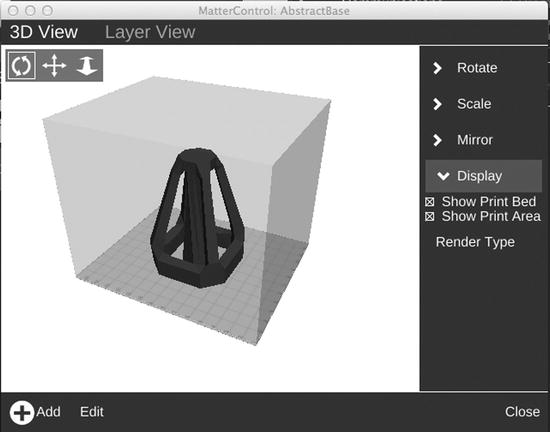
Figure 8-12. MatterControl 3D view of the piece as it will appear on the platform

Figure 8-13. MatterControl visualization of the first layer

Figure 8-14. MatterControl visualization of a layer partway up
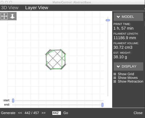
Figure 8-15. MatterControl visualization of a layer near the top (note layer count at bottom)

Figure 8-16. The real thing, partway done; note the grid infill

Figure 8-17. The final piece, in PLA on blue tape (with skirt)
Printing a Vase
STL files include just the surface of an object. When you create a model, the CAD software wallpapers the surface of the object you created with triangles. Normally, slicing software will automatically create infill to fill in the area inside your object to support it internally.
But suppose you want an object to stay hollow, with an open top, like a vase? Slic3r and Cura both have settings for number of top layers and number of bottom layers. If you set the number of top layers to zero, then there will not be a top layer. If that top layer was all that needed support, then the program will not generate any support inside the vase either, and voila—you have your vase. If you specify a nonzero number of top layers when you have selected Spiral Vase, the slicing programs ignore the top layers.
Taking this a step further, if you want to control building up the vase in the vertical direction so there is no visible seam in your delicate vase, you can use the Spiral Vase setting under Print settings, as shown in Figure 8-18. Spiral Vase creates the object by spiraling up from the base rather than by stepping up in discrete layers. The vase walls are just one layer thick with this setting, which can be fairly delicate. Whether a “vase” made in this way will hold water is an open question!
Figure 8-18 shows the settings to create a very simple, small vase (maybe good for one shamrock?) in OpenSCAD (see Chapter 4 for more on OpenSCAD). The entirety of the code is this line:
linear_extrude(height = 50, convexity = 10, twist=60,center=true,scale=0.8) square([25,20]);

Figure 8-18. Selecting vase settings in MatterControl; otherwise we used the same settings as for the simple objects
Figure 8-19 shows the resulting vase, printed in PLA.
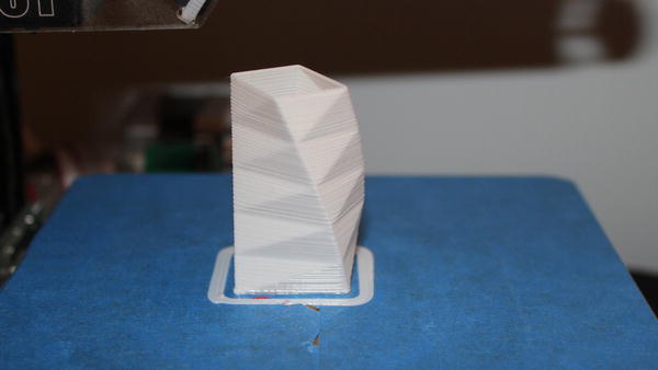
Figure 8-19. The resulting mini-vase
Printing a Complex Object with Fine Detail
Some objects are so complex that slicing can take hours, either because the shape is complex or there is a lot of fine detail or both. In those cases, changing a few settings can speed up the generation of the G-code file, with a little bit of risk that the structure will suffer.
A gimbal is a support that allows something to pivot freely about an axis. According to Wikipedia, the inventor of the gimbal is lost in the mists of time; gimbals have long been used on board ships to isolate items from the rolling motion of the waves or to maintain the upright position of an item from the effects of rolling waves. An example of this is the three-ring gimbal designed by Diego Porqueras in Solidworks, shown in Figure 8-20.
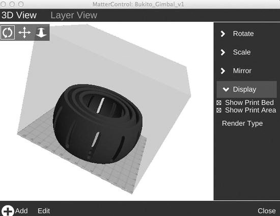
Figure 8-20. A three-ring gimbal
![]() Tip If you want to try this gimbal yourself, download the STL from Youmagine at
Tip If you want to try this gimbal yourself, download the STL from Youmagine at
www.youmagine.com/designs/bukito-gimbal-demo-print.
This gimbal works by having small protrusions on the rings with corresponding holes in the other rings. Slicing this object without some prior thought can result in very, very long slicing times. However, a few minor adjustments can reduce the time to a reasonable period. There is a setting called Avoid Crossing Perimeters under Print, then Layers and Perimeters in Slic3r. Unchecking this box and the “thin walls” box makes the process vastly faster by reducing the amount of inter-triangle checking the slicing program has to do. If you uncheck these settings, watch your print carefully for a few layers and review the visualizations. Figure 8-21 shows the settings that are changed from the earlier “Simple Print” baseline ones.
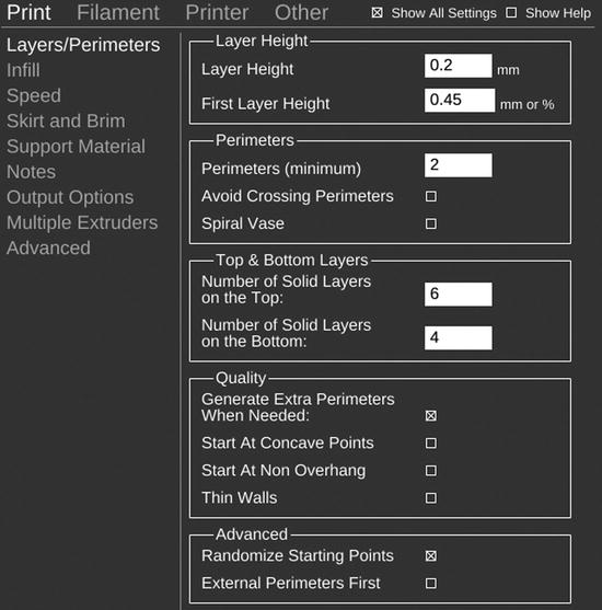
Figure 8-21. Changes to simple object settings for the gimbal
A perusal of the layer visualizations (Figure 8-22) shows that some of the layers near the center of the print will have these protrusions. The shells are nearly hollow, with just 12% infill in this case. Figure 8-23 lets you see what this looks like on the printer.
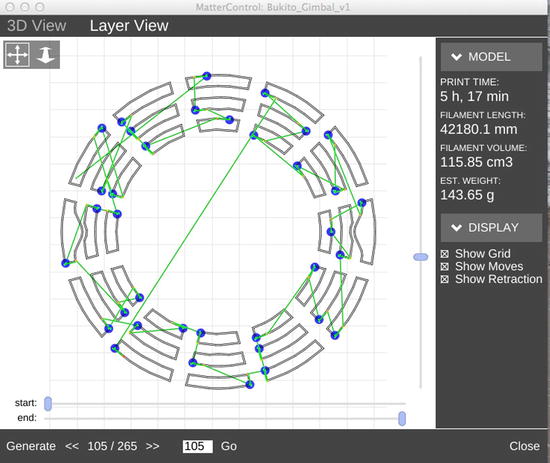
Figure 8-22. A layer in the region that comprises the gimbal pivots

Figure 8-23. An intermediate layer of the actual print
The finished gimbal turns about two axes, as shown in Figure 8-24.

Figure 8-24. The finished gimbal on the printer; it moves freely about two axes
This print could have very easily been impossible without a bit of thought. If the pivots had been tiny, thin ones instead of the gradual, curved ones you can see in Figure 8-22, it would have been very difficult to print. The decorative holes are oriented vertically so that there are small, curved areas to bridge across, and the pivots do not stress the printer’s capability. Avoiding long, skinny protrusions parallel to the build plate or small protrusions in general raises the likelihood of a successful print.
Printing with Support
In Chapters 4 and 5 you saw a variety of examples using a bear that required support to print correctly (unless it was cut in half). We tried various angles in Chapter 5; here we will put the bear on his tail to see how that works out. Figure 8-25 shows MatterControl’s visualization of the bear on the platform in this orientation.

Figure 8-25. The bear on the platform, tail down
The support structure will need to support the bear’s rear and his front legs. Figure 8-26 is a cross-section partway through the build that tells us that there will be two bars of support (the two smaller cross sections) in addition to the bear itself.

Figure 8-26. A typical layer showing a cut through the main part and the support
Generating basic support is straightforward; you tick the box labeled Generate Support Material under Print Settings and then Support Material in the slicing program, as shown in Figure 8-27. We set the Overhang Threshold angle where support starts to be generated to 45 degrees. (Refer back to Chapter 5’s section about support for details about overhangs.) This time we used the MatterSlice slicing engine to see if it will be different from the previous Slic3r attempts with this piece.

Figure 8-27. MatterSlice support settings used in this example
The next two figures show the bear building up. First the program creates a wide skirt (Figure 8-28), the support for the rear of the bear. Because only the tip of its tail actually touches the platform in this orientation, the initial layers are more or less all support. Then in Figure 8-29, we see the bear partially finished, with the columns of support under where his front legs will be. Note that these pillars of support are the smaller, cross-sectioned areas in Figure 8-26.

Figure 8-28. The first (nearly all support and skirt) layers of the bear

Figure 8-29. The bear’s support starting to build up
When the bear is complete (Figure 8-30), it has three areas of support: one under the tail, and one under each front leg. The front leg ones will snap off relatively easily. This time we used a different slicing engine than we did in the previous chapters, but we also used a different orientation. Sometimes a bit of experimentation will reveal that certain pieces of software handle certain cases better than others.
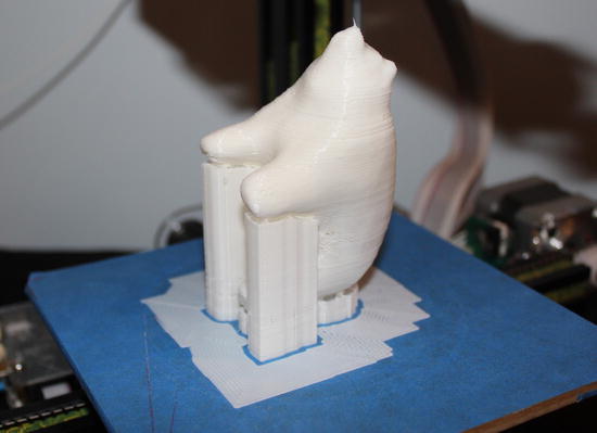
Figure 8-30. The completed bear and support
![]() Tip Some objects have particularly awkward support needs. For example, the Herreshoff cleat historic nautical reconstruction project in Chapter 12 needs support under its protruding parts parallel to the ground, but really does not need support in some hollow enclosed areas.
Tip Some objects have particularly awkward support needs. For example, the Herreshoff cleat historic nautical reconstruction project in Chapter 12 needs support under its protruding parts parallel to the ground, but really does not need support in some hollow enclosed areas.
Hand-Building Support
Sometimes a model’s geometry only requires support in one place (for example, just one long protrusion, like an outstretched arm or hand). In those cases, the slicing programs might decide that you need support in all kinds of places. An alternative is to figure out some minimal support yourself and create a small object or two that you place underneath the problem area to hold it up, just as you would stick a folded-up piece of cardboard under a too-short table leg.
You can use any of the programs from Chapter 4 to create a rectangular solid (or more complex piece) to tuck under the problem area. Then you can add this piece to the build platform in either Repetier Host or MatterControl right along with your primary piece and tuck it under the problematic piece. Make sure that this piece (which is a 3D-printed project in its own right) has enough of a base so that it does not just fall over, and design it so that it is easy to snap off the primary piece. This is rarely necessary, though, and is a last resort if the existing tools just will not work for you.
Dual Extruders
A printer with dual extruders allows you to print in two colors or two materials. Exactly how this works depends a lot on the dual extruder machine in question, but this general guide will give you some ideas on how to get started with your machine. You can use a dual extruder machine in two ways. First, you can use a dissolvable support material in one extruder so that you can just wash off support. Alternatively, you can print in two materials or two colors. We will look at each of these.
![]() Note This section was originally written by the author of this book for the Deezmaker Bukobot Wiki. You might check there for any updates and examples of duo prints at www.bukobot.com.
Note This section was originally written by the author of this book for the Deezmaker Bukobot Wiki. You might check there for any updates and examples of duo prints at www.bukobot.com.
Dual Extruders: Using One Head for Support Material
If you are printing something with significant amounts of support material, you can use dissolvable support. In this case, you can use the regular Repetier Host interface to slice your model. You need to change the Slic3r Printer settings to two extruders and set the support material to be one of the extruders.
![]() Caution You will need to tell your slicing program some details of your dual extruders, most notably how much they are offset from each other. Your manufacturer may have told you this, or you may need to deduce it. The process for deducing this on Deezmaker printers is outlined at www.bukobot.com, which might give you some ideas if you do not have any information on a dual extruder printer that you happen to have acquired.
Caution You will need to tell your slicing program some details of your dual extruders, most notably how much they are offset from each other. Your manufacturer may have told you this, or you may need to deduce it. The process for deducing this on Deezmaker printers is outlined at www.bukobot.com, which might give you some ideas if you do not have any information on a dual extruder printer that you happen to have acquired.
Dual Extruders: Models in Two Colors (or Two Materials)
When you are printing models in two colors (or two materials), you need to follow a somewhat different process than you did for one-color printing. You need to create two STL files that are interleaved into an .AMF (additive manufacturing file format) file. Note that any rotation needed when arranging the files for printing has to be done in the STL file generation, because this process does not allow for any rotation in Slic3r.
You also have to split your model into two STL files so that there are no places with structure created with both colors trying to occupy the space. If something penetrates something else, there must be a hole in the one object to accommodate the second, just as in physical space. The following exercise explains this in more detail.
The steps, then, go like this:
- First, generate your STL file in two parts, but interleaved as they will be in the print.
- In OpenSCAD, for example, if you plan ahead that you are developing a file for two extruders, you can add ! in front of a structure to include only the structures included in that structure, and * at the front to exclude a particular structure. Figure 8-31 shows this code in OpenSCAD before anything is separated out for two extruders.
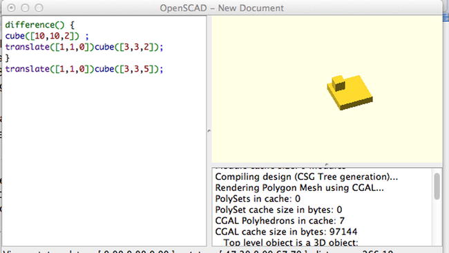
Figure 8-31. OpenSCAD code for this example
Change the code as shown in the following snippet to export the larger square with a hole in it and export that first STL file (note exclamation point ahead of difference):
!difference() {
        cube([10,10,2]) ;
        translate([1,1,0])cube([3,3,2]);
}
translate([1,1,0])cube([3,3,5]);
![]() Note This example as described here has coincident faces and could have resulted in a non-manifold mesh, particularly in older versions of OpenSCAD. This example went through slicing and printing without issues. If you wanted to make absolutely certain that you would not have to clean up some non-manifold faces later (as described in the section on watertight and manifold models in Chapter 5’s discussion on slicing a model using Slic3r in Repetier Host), the cube being subtracted should extend past the faces of the one from which you are subtracting it. However, this means that you cannot use the simple, symmetrical process explained here. If your slicing software complains about a non-manifold edge, go back and extend the piece you are subtracting a little so that it does not exactly lie on a face.
Note This example as described here has coincident faces and could have resulted in a non-manifold mesh, particularly in older versions of OpenSCAD. This example went through slicing and printing without issues. If you wanted to make absolutely certain that you would not have to clean up some non-manifold faces later (as described in the section on watertight and manifold models in Chapter 5’s discussion on slicing a model using Slic3r in Repetier Host), the cube being subtracted should extend past the faces of the one from which you are subtracting it. However, this means that you cannot use the simple, symmetrical process explained here. If your slicing software complains about a non-manifold edge, go back and extend the piece you are subtracting a little so that it does not exactly lie on a face.
Change the code to look like the following (adding an exclamation point ahead of translate) to output the smaller box that will penetrate the larger one, and then export the second STL file that will make up this object:
difference() {
          cube([10,10,2]) ;
         translate([1,1,0])cube([3,3,2]);
             }
!translate([1,1,0])cube([3,3,5]);
After this exercise you will have two STL files. To slice the files, you have to use Slic3r itself, not a host program. Here is the process:
- Bring up Slic3r, and in the File menu select Combine Multi-material STL Files. Bring in the files and then click Cancel when you have brought in both files.
- The Filament setting on top is for Extruder 1.
- The program will create a file ending in .amf.xml, which combines the two. Set your Print, Filament (for both extruders) and Printer settings. Then click Export G-Code to get your G-code.
- To print your piece, go into a host program and import the G-code you just made. Run as normal.
- If your model needs support, in your Slic3r settings under Support you can decide which extruder’s material you want to use for support. This material will be used throughout the model, even to support materials from the other extruder.
Figure 8-32 shows how the box within a box code in the preceding example turned out on a Deezmaker Bukobot Duo. Note that this process in Slic3r generates the little wall around the piece visible in Figure 8-32, called a full-height skirt. It’s intended to wipe off the extruder between colors on each layer. Cura follows the shape of the layer rather than making a constant-width wall and thus builds a sort of wrapper that has to be cut off but is a more efficient use of filament.
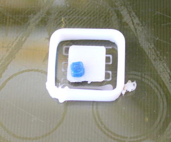
Figure 8-32. The small dual extruder test on a Kapton tape platform, printed in two colors of ABS on a Bukobot Duo
Be sure you rotate the entire model before exporting from the program you are building in (here, OpenSCAD) because the combination file, in Repetier Host as of this writing at least, does not allow rotation.
![]() Tip If you are using a dual-extruder 3D printer to print two colors and, on top of that, support is needed, you will need to pick one of the extruders to do the support for both materials.
Tip If you are using a dual-extruder 3D printer to print two colors and, on top of that, support is needed, you will need to pick one of the extruders to do the support for both materials.
Speed Settings
You probably noticed that there were many speed settings under the Print category. By and large, as a beginner it is best to set these to your manufacturer’s specifications and then leave them alone. However, if you start printing with more exotic filaments (see Chapter 7), you may want to slow down the print. Experts also often adjust the first layer speed downward to ensure that the first layer has the best possible chance of sticking. If your prints are not sticking, slowing down the first layers might be a technique to try.
Adjusting speed is still largely an empirical exercise with consumer open source printers, and with experience you will begin to see what types of print your particular printer might have trouble with and thus might benefit from a slower print. Slowing down a print does have its issues, though. There’s the obvious one of lowering printer throughput if you are using your printer to complete a project on deadline, so you may not want to just keep cranking down the speed unless it looks like the only option.
Summary
This chapter has tied together the material in Chapters 4 through 7 by walking you through some examples. These examples detailed the settings that you would use for prints similar to these circumstances. A few standard combinations of settings should serve you well for most of your projects; learning when you need to get more creative is knowledge that will come with experience.
Next you will learn more about what to do with your print after it finishes printing, with an explanation of some metal-casting processes and some post-processing techniques in the next few chapters. After that, we will get into some applications and predictions for the future—always a dangerous exercise in the fast-changing world of 3D printing.