Chapter 11. Deploying VPNs with PKI Using Cisco Security Manager
This chapter covers the following topics:
• Deploying PKI as a Service Using CSM
• Cisco ASA IPsec VPN Remote Access Using CSM
• DMVPN Using CSM
• GETVPN Using CSM
Chapter 6, “Integration in Large-Scale Site-to-Site VPN Solutions,” discusses that it takes a number of steps to deploy VPN technologies using the Cisco command-line interface, which includes configuring enrollment options, ISAKMP policy, IPsec profile, and VPN technology-specific configurations. This multistep process becomes more tedious when configuring on multiple devices. Moreover, configuring over command-line interface does not support any kind of validation of the configurations. Therefore, using a management tool to deploy these technologies would make installation and management of large number of devices easier and more efficient. This chapter illustrates the deployment of these technologies using Cisco Security Manager (CSM), which is a management tool that provides an ideal solution for large or complex deployments. The following are benefits of a CSM solution:
• Ability to configure, tune, and manage Cisco Firewalls, VPNs, intrusion prevention system (IPS) sensors, and integrated security services across multiple platforms
• Can work with Cisco Secure Access Control Server (ACS) to provide role-based access control
• Flexible device management options, including policy-based management and various methods of deploying configuration changes
The VPN deployments illustrated in Chapter 6 and Chapter 7, “Integration in Remote Access VPN Solutions,” mainly illustrate the use of the Cisco command-line interface. This chapter illustrates the same deployments using CSM.
Cisco ASA IPsec VPN Remote Access
The Cisco IPsec VPN remote access solution also leverages IKE protocol for key negotiation between the clients and the gateways. As we have described in earlier chapters, two methods are available in which both the client and the gateway authenticate with each other before deriving the keys: using preshared keys or digital certificates. With remote access you can have a preshared key for every user, but that does not scale when a large number of users exists. Therefore, the remote user authenticates with s a group-based preshared key and x-auth to do per-user authentication. The disadvantage of using group-based authentication is it opens a security hole when a user leaves the group but still has the group-based keys. Therefore, to enhance better authentication, the remote users can use digital certificates and x-auth for per-user authentication. Before discussing how to use PKI as a service for remote access solutions, you need to review Easy VPN.
Easy VPN Overview
The Easy VPN Server feature enables Cisco IOS routers, Cisco Adaptive Security Appliances (ASA), and Cisco PIX Security Appliances to act as headend devices in site-to-site or remote-access VPNs. The feature pushes security policies defined at the central site to the remote device so that it has up-to-date policies in place before a connection is established. It can also terminate VPN tunnels initiated by remote workers running the Cisco VPN Client software on PCs. This flexibility enables mobile and remote workers to access critical data and applications on their corporate intranet.
Deploying IPsec VPN Remote Access on the ASA Using CSM
This section describes the deployment of a remote access solution using ASA as the VPN gateway for remote clients. Figure 11-1 illustrates the topology used in this deployment example.
Figure 11-1 Remote Access VPN Solution Diagram

Following are some of the design considerations for the topology in Figure 11-1:
• The sub-CAs should be reachable by WAN (Internet). This enables the remote clients to obtain their certificates.
• The sub-CAs and ASAs might be reachable via an internal network or through the Internet. This design assumes they would reach through the Internet.
• The ASAs are used as VPN gateways and are configured in active/standby mode.
• CSM reaches the ASA firewalls using the internal network.
Adding the Device into the CSM Domain
With CSM 4.0 installed, you can use it to deploy VPN with PKI as a service. To begin, add the device into the CSM domain, as described in the upcoming steps, as shown in Figure 11-2.
Figure 11-2 Steps for Adding Device into CSM Domain

Figure 11-3 shows the initial screen.

Step 1. Add the device’s general properties, as shown in Figure 11-4.
Figure 11-4 Adding Device General Properties

Step 2. Add the device’s credentials, as shown in Figure 11-5.
Figure 11-5 Adding Device Credentials

Now the device is ready to be added to the CSM domain. Click the Test Connectivity button to see if the connectivity is successfully established between the CSM and the device.
Configure Enrollment Options
With the device added to the CSM domain, now configure the enrollment options, as illustrated in Figure 11-6 and described in the following steps:
Step 1. Configure the sub-CA information (ra-subca), as shown in Figure 11-7. The fingerprint information must be supplied for enrollment.
Step 2. Configure the subject name parameters for the ASA, as shown in Figure 11-8.
Step 3. Configure the trusted hierarchy, as illustrated in Figure 11-9.
As shown in the Figure 11-9, ASA needs to obtain the root CA certificate only for the purpose of authenticating ra-subca. ASA needs to know that the CA server to which it is enrolling is truly authenticated by the root CA.
Step 4. Obtain the root CA certificate, as illustrated in Figure 11-10.
Figure 11-6 Enrollment Option Steps

Figure 11-7 Configuring Sub-CA Information

Figure 11-8 Configuring Subject Name Parameters for ASA


Figure 11-10 Obtaining Root CA Certificate

Now the certificate chaining is complete. At this point, ASA will have not only its certificate obtained by ra-subca, but also the root CA certificate for chain verification.
Configure the Certificate Map
The next important step is to configure the certificate map, which is used to map the incoming requests to the right tunnel group. In this example, the incoming requests are mapped to a tunnel group “testgroup.” This certificate map enables certificates issued by ra-subca. Figure 11-11 shows how to configure the certificate policy.
Figure 11-11 Configuring Certificate Policy

Figure 11-12 illustrates the completed configuration of the certificate map.

Configure Remote Access VPN
Configure remote access configuration using CSM through the following steps, as illustrated in Figure 11-13.
Figure 11-13 Remote Access VPN Configuration Steps

Step 1. Configure a group policy, as illustrated in Figure 11-14.
Figure 11-14 Creating a Group Policy

Step 2. Configure the group’s properties, as illustrated in Figure 11-15.

Step 3. Configure tunnel group name, as illustrated in Figure 11-16.
Figure 11-16 Configuring Tunnel Group Name

Step 4. Configure the tunnel group properties, as illustrated in Figure 11-17.
Figure 11-17 Configuring Tunnel Group Properties
Step 5. Configure IKE proposal, as illustrated in Figure 11-18.

Step 6. Create the IPSec proposal, as illustrated in Figure 11-19.

Step 7. Start the Configuration Wizard, as illustrated in Figure 11-20.
Figure 11-20 Remote Access Configuration Wizard

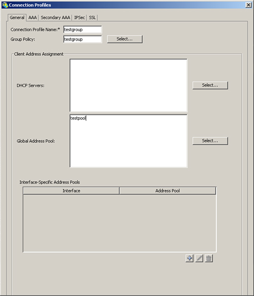
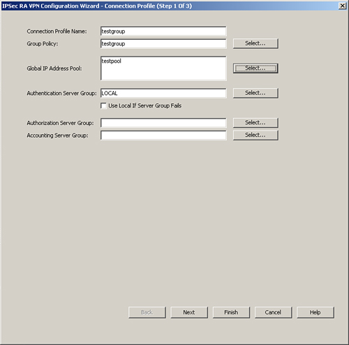
Step 8. Configure the connection profile, as illustrated in Figure 11-21.
Figure 11-21 Configuration Wizard, Connection Profile
Step 9. Configure the IPsec settings, as illustrated in Figure 11-22.
Figure 11-22 Configuring Remote Access, IPsec Settings

Step 10. Configure the defaults, as illustrated in Figure 11-23. Click Finish to exit the Configuration Wizard.
Figure 11-23 Configuring Remote Access Defaults

Deploying DMVPN Using CSM
DMVPM can also be deployed using CSM. Figure 11-24 illustrates the flow of this operation.
Step 1. Configure name and technology, as illustrated in Figure 11-25.
Step 2. Select the hub-and-spoke endpoints, as illustrated in Figure 11-26.
Step 3. Select the WAN interfaces and local interfaces, as illustrated in Figure 11-27.
Figure 11-24 DMVPN Deployment Process Flow

Figure 11-25 Configuration of Name and Technology

Figure 11-26 Selecting Devices: Hub and Spoke

Figure 11-27 Selecting Endpoints

VPN Policy Configuration
You have now set up the first half of your deployment. The following steps and Figure 11-28 illustrate the second set of steps: VPN policy configuration.
Figure 11-28 DMVPN Deployment: VPN Policy

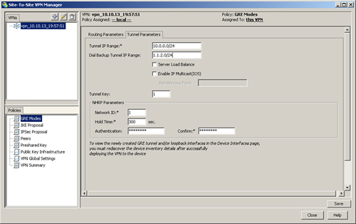
Step 1. Configure the GRE tunnel, as illustrated in Figure 11-29.
Figure 11-29 GRE Tunnel Configuration
Step 2. Configure the routing associated with the DMVPN tunnel, as illustrated in Figure 11-30.
Figure 11-30 DMVPN Routing Configuration

Step 3. Configure the IKE proposal, as illustrated in Figure 11-31.
Figure 11-31 IKE Policy Configuration

Step 4. Configure IPsec proposal, as illustrated in Figure 11-32.
Figure 11-32 IPsec Policy Configuration

Step 5. Configure the PKI trustpoint configuration. (Refer to Chapter 7 for a definition of trustpoint configuration.) Select trustpoints for DMVPN deployment, as illustrated in Figure 11-33.
Figure 11-33 Trustpoint Configuration

Step 6. Review the deployment summary, as illustrated in Figure 11-34.
Figure 11-34 Deployment Summary

Step 7. Finally, select Submit to deploy the configuration at both the head and spoke.
GETVPN Deployment Using CSM
GETVPN is an any-to-any technology, which means that no hub-and-spoke communication occurs; rather, GETVPN is mainly spoke-to-spoke communication. The two major components of GETVPN technology are key server and group member. A key server securely distributes keys to various group members. Group members need to register with a key server before initiating communication with other group members.
Note
For more information on the GETVPN design, refer to http://www.cisco.com/en/US/prod/collateral/vpndevc/ps6525/ps9370/ps7180/GETVPN_DIG_version_1_0_External.pdf.
To deploy GETVPN using CSM, follow these steps:
Step 1. Configure name and technology, as illustrated in Figure 11-35.
Figure 11-35 Configuration of Name and Technology
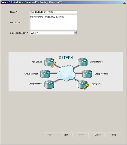
Step 2. Select GETVPN, as illustrated in Figure 11-36.
Figure 11-36 Selecting the VPN Technology
After selecting the technology, configure the policy. Figure 11-37 and the following steps describe the process flow for deploying a GETVPN configuration.
Figure 11-37 Deploying GETVPN Process Flow

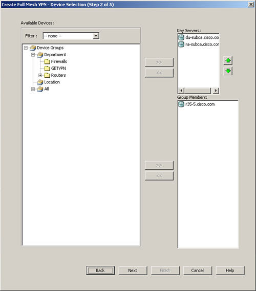
Step 1. The Group member policy consists of two parts: group settings and security associations. Configure the Group settings, as illustrated in Figure 11-38.

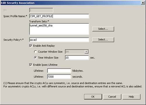
Step 2. Configure the security association, as illustrated in Figure 11-39.
Figure 11-39 Security Association
Step 3. The group member policy appears, as shown in Figure 11-40. The group member configuration consists of defining the external WAN interface and the key servers deployed.
Figure 11-40 Group Member Policy

Step 4. Configure the IKE proposal, as illustrated in Figure 11-41.
Figure 11-41 IKE Policy Definition

The IKE policy uses digital certificates with 3DES for encryption and md5 for authentication.
Step 5. Configure the Key server policy, as shown in Figure 11-42.
Figure 11-42 Key Server Configuration

Step 6. Select the trustpoint configuration, as shown in Figure 11-43.
Figure 11-43 Trustpoint Configuration
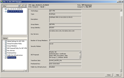
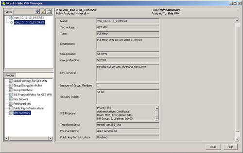
When the preceding configuration is completed, the VPN summary shows all the pieces together, as illustrated in Figure 11-44.
Summary
This chapter looked at how to deploy VPN technologies using PKI as service with CSM as the management tool. A number of benefits exist for using CSM rather than using a command-line interface, such as validation of configs and the ability to deploy on a large number of devices.