
In order to test the application, we will have to execute a ping from the host 1 to host 3. The following sequence of events will take place once you send the ping request from host 1 to host 3:
- ARP request: An address resolution needs to occur because host 1 does not have knowledge of host 3 MAC's address. Therefore, there is an ARP request broadcast from host 1, which is received by host 2 and host 3.
- ARP reply: An ARP reply is sent from host 3 to host 1.
- ICMP echo request: Host 1 then sends an echo request to host 3 because it knows the MAC address of host 3.
- ICMP echo reply: Host 3 also knows the MAC address of host 1; therefore, an echo reply is sent from host 3 to host 1.
In order to understand the packets received by each host in the topology, it is required that we run the tcpdump command:
- Host 1: tcpdump -en -i h1-eth0
- Host 2: tcpdump -en -i h2-eth0
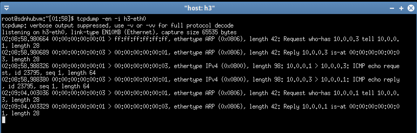
- Host 3: tcpdump -en -i h3-eth0
The result should be in the following format:

Next, we ping from host 1 toward host 3:
mininet> h1 ping -c1 h3
PING 10.0.0.3 (10.0.0.3) 56(84) bytes of data.
64 bytes from 10.0.0.3: icmp_seq=1 ttl=64 time=10.4 ms
--- 10.0.0.3 ping statistics ---
1 packets transmitted, 1 received, 0% packet loss, time 0ms
rtt min/avg/max/mdev = 10.417/10.417/10.417/0.000 ms
mininet>
From the preceding result, we can see that the ICMP request has returned successfully. We will then check the flow table of the switch (s1):

From the preceding screenshot, we can see two new flow entries of priority level 1, which have been registered:
- Receive port in_port=3, destination MAC address dl_dst=00:00:00:00:00:01, actions=output:1.
- Receive port in_port=1, destination MAC address dl_dst=00:00:00:00:00:03, actions=output:3.
From the preceding screenshot, the first entry appeared twice: {n_packet=2}. It comprised communication from host 3 to host 1, which is the ARP reply and ICMP echo reply. The second entry is one, which comprises the ARP request that was broadcast from host 1.
Next, we will look at the output of example_switch_13 running on the Ryu controller:

From the preceding log, we notice that there are three events logged:
- ARP request where host 1 (00:00:00:00:00:01) sends a broadcast (ff:ff:ff:ff:ff:ff).
- ARP reply from host 3 (00:00:00:00:00:03) to host 1 (00:00:00:00:00:01)
ICMP echo request from host 1 to host 3. - Finally, we will look attcpdump of all the hosts.
Host 1 broadcasts the ARP request first and then receives the ARP reply returned from host 3. After this, host 1 issues the ICMP echo request and receives the ICMP echo reply returned from host 3, as shown in the following screenshot:

Host 3 receives the ARP request issued by host 1 and returns the ARP reply to host 1. Host 3 then receives the ICMP echo request from host 1 and returns the echo reply to host 1, as shown in the following screenshot:
The preceding Net App of the simple switching hub describes the steps in implementing a Ryu application.