5
Torsion of Non-circular Shafts
5.1 INTRODUCTION
Generally for power transmission, circular shafts are used because there is uniform stress distribution along any radius of the shaft. Plane sections of shaft remain plane after the application of twisting moment, as a result there is no distortion in the sections of shafts and change in volume of the shaft is zero.
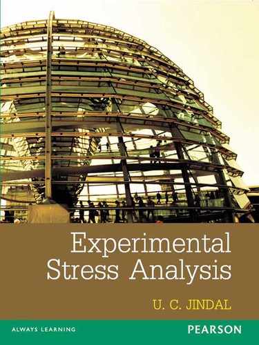
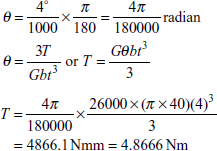
For stationary torque application, non-circular shafts of different sections such as square, rectangular, triangular, elliptical solid, or hollow are used. The assumption that transverse sections of the shaft remain plane after the applications of torque does not hold good for shaft of non-circular section. Only the lines of symmetry remain straight; all other lines in the section go out of plane and the section gets severely distorted. Figure 5.1shows the undeformed shaft of square section and deformed shape after the application of twisting moment along the axis of the shaft.
Figure 5.2 shows the formation of ridges and valleys in the square section of a shaft. Shaft of rectangular section subjected to axial torque T.
A rectangular shaft of section 2b × 2a, fixed at one end, is subjected to axial torque T as shown in figure 5.3 which produces shear stress in shaft which is zero at centre and maximum at the outer surface, but varies from one radial line to another radial line. Figure 5.4 shows that the original plane cross-section has deformed or worked out of its own plane. In general, torsion of shaft which does not possess circular symmetry produces deformation that involves rigid body rotation of one cross-section with respect to another cross-section accompanied by warping out of the original plane. Figure 5.4 shows four dotted lines AC, BD, ac, bd, lines of symmetry remain straight, but all other lines in the cross-section deform when the shaft is twisted.
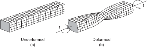
Figure 5.1 Formation of ridges and valleys
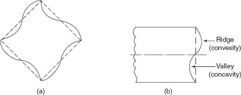
Figure 5.2 (a) Change of shape of cross-section (b) Warping
Figure 5.3 Shaft of rectangular section subjected to axial torque T
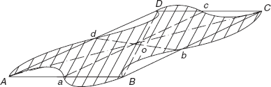
Figure 5.4 Distortion in rectangular section
All non-circular sections are distorted under torsion to a greater or lesser degree. For sections close to circle, these effects are less marked as in the case of elliptical section.
The detailed analysis on torsion of non-circular shafts including the warping of the sections is beyond the scope of this book. However, the results of the theory developed by St. Venant and Prandtl for the calculation of maximum shear stress and angular twist in non-circular shafts are summarized in this chapter.
5.2 RECTANGULAR SECTION
Torque T = GJθ
where GJ = |
Torsional rigidity of the shaft, |
θ = |
angular twist per unit length, and |
J = |
Ka3b. |
Angular twist,
The value of constant K depends upon the ratio of ![]() , where 2b is the longer side of the rectangular section and 2a is the shorter side of the section as shown in Figure 5.5. The values of K for various ratios of
, where 2b is the longer side of the rectangular section and 2a is the shorter side of the section as shown in Figure 5.5. The values of K for various ratios of ![]() are given in Table 5.1.
are given in Table 5.1.
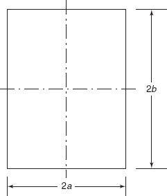
Figure 5.5 Rectangular section
Maximum shear stress, ![]()
where K1 is another constant again depending upon the ratio of ![]() .
.
or
where
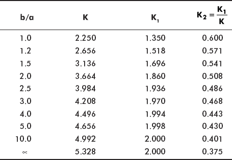
The constants K, K1, and K2 are shown in Table 5.1.
Table 5.1 Values of constants for rectangular section
Expressions for θ and τ can be approximately given as follows, and then one does not need to refer to the table of constants
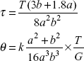
where
For the sake of comparison let us take ![]() = 1.5
= 1.5
From tables K = 3.136, K1 = 1.696, K2 = 0.541
Maximum shear stress, ![]()
Angular twist per unit length ![]()
From approximate analysis
Maximum shear stress, ![]()
Angular twist per unit length
If we compare the results of maximum shear stress and angular twist, from two analyses, we can find only negligible difference between the two analysis.
The maximum intensity of shear stress, τ, occurs at the centre of the longer side as shown in Figure 5.6. Figure 5.7 shows the distortion of the ends of a shaft of square section.
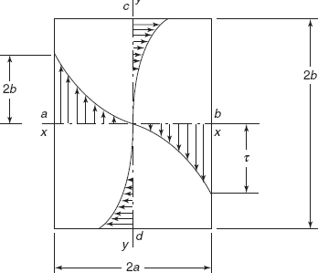
Figure 5.6 Shear stress distribution in shaft of rectangular sections
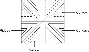
Figure 5.7 warping of a square section
Example 5.1 A 50 mm × 25 mm rectangular steel shaft is subjected to a torque of 1.0 kNm. What is the maximum shear stress developed in the shaft and what is the angular twist per unit length? G = 80 GN/m2.
Solution: |
G = 80 GN/m2 = 80 × 109 N/m2 = 80 × 103 N/mm2 |
Longer side, |
2b = 50 mm, b = 25 mm |
Shorter side, |
2a = 25 mm, a = 12.5 mm |
Torque, |
T = 1.0 kNm = 1.0 × 10⁶ Nmm |
Maximum shear stress, ![]()
From tables for
Angular twist per unit length,
|
|
|
|
|
|
= |
0.06987 × 10⁻³ radian per mm length |
|
|
= |
0.06988 radian/metre length |
|
|
= |
4.0 degrees per metre length |
Example 5.2 A rectangular shaft 6 cm × 4 cm made of steel is subjected to a torque of 3000 Nm. What is the maximum shear stress developed in the shaft and what is the angular twist per metre length? G = 80 kN/mm2. Use approximate relationship.
Solution: |
|
Torque, |
T = 3 kNm = 3 × 10⁶ Nmm |
Longer side, |
2b = 6 cm, b = 3 cm = 30 mm |
Shorter side, |
2a = 4 cm, a = 2 cm = 20 mm |
|
G = 80 kN/mm2 |
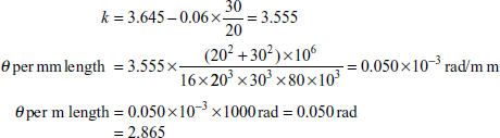
Maximum shear stress,
Angular twist per mm length
where
Exercise 5.1 A rectangular shaft of section 60 mm × 24 mm made of steel is subjected to a torque such that maximum shear stress developed in shaft is 40 N/mm2. What is the magnitude of the torque and what will be the angular twist in 1 m length of the shaft? G = 80 kN/mm2. Take values of constants from the table.
Ans. [355 Nm, 1.23°].
Exercise 5.2 A rectangular shaft of steel 96 mm × 60 mm is subjected to a torque such that the angular twist in a length of 1 metre is 0.5°. What is the magnitude of the torque and what is the maximum shear stress developed in the shaft section?
Ans. [3.876 Nm, 44.26 MPa].
5.3 TORSION OF ELLIPTICAL SECTION SHAFT
For the elliptical section shaft, the expressions for maximum shear stress and angular twist per unit length are
and
where b = semi-major axis and a = semi-minor axis of ellipse.
Maximum shear stress occurs at the ends of the minor axis as shown in Figure 5.8, i.e. at the points B and D. Figure 5.9 shows the contour lines of constant displacement. The convex portions of the cross-section, where displacements in the direction of axis of the shaft are positive, are shown by continuous lines. Where the surface is depressed, depressions are shown by dotted lines.
Example 5.3 A shaft of elliptical section with minor axis 2a and major axis 2b is subjected to a torque of 2 kNm. If the maximum shear stress in the shaft is not to exceed 80 N/mm2, determine the major and minor axes, if b = 1.5a. What will be the angular twist in a metre length in this shaft under the given torque? G = 80000 N/mm2.
Solution: b = 1.5 a
Maximum shear stress, ![]()
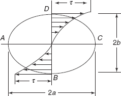
Figure 5.8 Maximum shear stress occurs at the ends of the minor axis
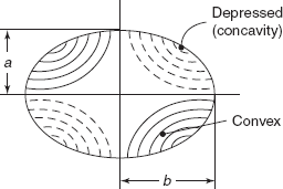
Figure 5.9 Contour lines of displacement
|
|
|
|
|
Minor axis |
= |
44 mm |
|
Major axis |
= |
66 mm |
Angular twist per mm length
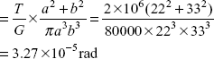
θ per metre length = 3.27 × 10–2 = 1.87°
Exercise 5.3 A shaft of elliptical section with major axis 60 mm and minor axis 40 mm is subjected to an axial twisting moment of 0.5 kNm. What is the maximum shear stress developed in the section and what is the angular twist per metre length? G = 40 kN/mm2.
Ans.[24.5 MPa, 1.37°].
5.4 TORSION OF A SHAFT WITH EQUILATERAL TRIANGULAR SECTION
Figure 5.10 shows an equilateral triangle section of a shaft subjected to the twisting moment T. Say a is the side of the equilateral triangle. Maximum shear stress occurs at the centre of the sides.
Angular twist per unit length
Maximum shear stress,
At the corners of the triangle, i.e. at A, B, and C, shear stress is zero.
Example 5.4 A shaft of equilateral triangular section of side 40 mm is subjected to an axial twisting moment T. Determine the magnitude of T if the maximum shear stress is not to exceed 100 N/mm2. What will be the angular twist in 2 metres length of the shaft? G = 80000 N/mm2.
Solution: τ = 100 N/mm2
Side, a = 40 mm
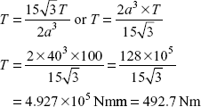
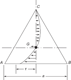
Figure 5.10 Shear stress distribution in equilateral triangular sections
Angular twist per metre length,
|
|
|
|
|
|
= |
0.0625 × 10⁻³ radian/mm length |
|
|
= |
0.0625 radian/m length |
Angular twist in 2 metres length |
= |
0.0625 × 2 |
|
= |
0.125 radian |
|
= |
7.162 degree. |
Exercise 5.4 A shaft of equilateral triangular section of side 60 mm is subjected to a torque of 1.0 kNm. Determine (i) maximum shear stress developed in shaft and (ii) angular twist per metre length of the shaft. G = 84 kN/mm2.
Ans. [60.14 N/mm2, 1.37°].
5.5 MEMBRANE ANALOGY
A German Scientist Prandtl analyzed that the solution of a partial differential equation that must be solved in the elastic torsion problem is mathematically identical to that for a thin membrane, such as a thin rubber sheet stretched over a hole, and the hole is geometrically similar to the cross-section of the shaft under study. On one side of the thin sheet, or membrane, there is a light air pressure. Following rules are followed for the analogous solution.
- Shear stress at any paint of the section (non-circular section of shaft) is proportional to the slope of the stretched membrane at that point.
- The direction of a particular shear stress at a point is at right angles to the slope of the membrane at the same point.
- Torque on the section is proportional to twice the volume enclosed by the stretched membrane.
Figure 5.11(a) shows that the area bound by the edges of a thin rubber sheet- membrane is of the shape of a shaft of non-circular section. The stretched sheet or membrane is subjected to an internal pressure and the membrane is deflected as shown in Figure 5.11(b). Take care that initial tension in membrane should be large enough, so that when membrane is blown up due to internal air pressure, changes in tension can be ignored. With the help of a travelling microscope, deflection at grid points on membrane can be noted down. And deflection contours (lines of constant deflection) are plotted as shown in Figure 5.11(c). From deflection contours, slope at any point of the section can be determined, as shown by a tangent at any point P of non-circular section. Knowing the results of a circular section shaft for a given torque, the membrane is calibrated for a circular section under a given pretension σ, internal pressure p, and membrane thickness.
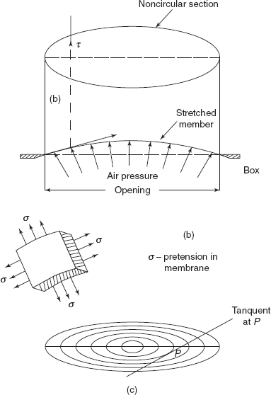
Figure 5.11 Deflection contour lines of membrane
5.6 TORSION OF THIN WALLED SECTIONS
Consider a shaft with thin walled tubular section subjected to a twisting moment T. The thickness of the tube can vary, and we have considered the section of variable thickness as shown in Figure 5.12(a). At any paint along the periphery say t is the thickness and τ is the shear stress. Take a small element abcd on the periphery of tubular section, with thickness t, at cd and t2 at ab. Since there is variation in thickness, there will be variable shear stress.
Figure 5.12 (a) Variable thin walled section (b) Sections of variable thickness
At cd, thickness is t1, and shear stress is τ1.
At ab, thickness is t2, and shear stress is τ2.
Axial length of element is dl. An enlarged view of the element is shown is Figure 5.12(b).
For equilibrium of forces
or
Now
t1τ1 = t2τ2 = tτ= q (shear flow)
= shear force per unit length
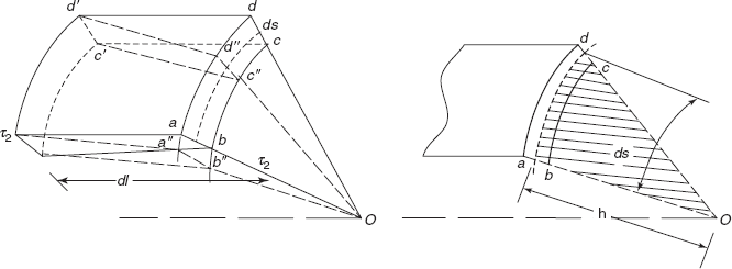
Figure 5.13 Element of variable thin walled section
Let us consider a small element of length ds along the periphery, say thickness is t
Shear force acting on the small element, dQ = qds
= shear flow × length. (Figure 5.13)
Moment of the force dQ at the centre O of the shaft
where q is shear flow q = τ. t.
|
δs |
− |
base of triangle (shaded area) |
|
h |
= |
altitude of the triangle. |
|
dT |
= |
q (hds) |
where = q 2 dA (where dA is the area of small triangle)
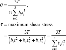
Total torque, ![]()
where A is the area enclosed by the centre line of the thin tubular section as shown for a rectangular section in Figure 5.14.
This equation T = 2q A is generally known as Bredt-Botha equation. (5.2)
Let us determine the angular twist in shaft. Consider a small element abcd of axial thickness dL. Due to the twisting moment point d is displaced to a″ and a is displaced to a″.
Shear force dQ or small element, = τtds
Say displacement of the edge ab or cd = δ
Shear strain, ![]()
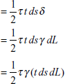
Strain energy for the small element =![]()
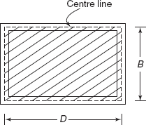
Figure 5.14 Thin rectangular section
But shear strain, ![]()
Shear strain energy ![]()
but ![]()
So, shear strain energy, ![]()
Moreover,
Let us take dL = 1, so that we can find out strain energy per unit length
Total strain energy per unit length ![]()
Using the Castigliano’s theorem,
angular twist θ per unit length ![]()
Again ![]()
where integral ![]() is the summation of (length/thickness) along the periphery of thin tubular section.
is the summation of (length/thickness) along the periphery of thin tubular section.
Example 5.5 A thin walled box section 3a × 2a × t is subjected to a twisting moment T. A solid circular section of diameter d is also subjected to the same twisting moment. Determine the thickness of the box section (a) if the maximum shear stress developed in box section is the same as that in solid circular section, and d = 2a, and (b) if the stiffness for both is the same under the same torque.
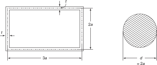
Figure 5.15 Example 5.5
Solution: Figure 5.15 shows the thin walled section 3a × 2a × t and a solid circular section of diameter d.
Maximum shear stress in circular section,
Shear flow in box section,

Taking a ≫ t (side ≫ thickness)
Maximum shear stress in box section,
But

or

Angular twist for solid circular shaft ![]()
or ![]()
where ![]()
but d = 2a
So,
Angular twist for the thin box section,
where area A = 3a × 2a = 6a2
and
But θ = θ′
So,
Exercise 5.5 A shaft of hollow square section of outer side 48 mm and inner side 40 mm is subjected to a twisting moment such that the maximum shear stress developed is 50 N/mm2. What is the torque acting on the shaft and what is the angular twist if the shaft is 1.6 m long? G = 80000 N/mm2.
Ans.[0.7744 kNm, 2.6°].
5.7 TORSION OF THIN RECTANGULAR SECTIONS
Figure 5.16shows a thin rectangular section subjected to the torque T. Thickness t of the section is small in comparison to its width b. This section consists of only one boundary. In this case maximum shear stress occurs at ![]()
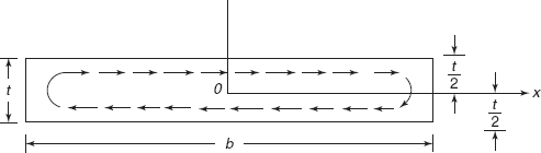
Figure 5.16 Shear stress flow as in thin rectangular sectors
If
θ = angular twist per unit length
T = torque on the section
T = ![]() (5.5)
(5.5)
Angle of twist per unit length,
These results can be applied to sections built up of rectangular strips and having only one boundary such as Angle Section, I section, T and channel sections as shown in Figure 5.17.
In the case of channel section and I section,
Torque,
Angle of twist per unit length,
In the case of Angle section and T section,
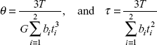
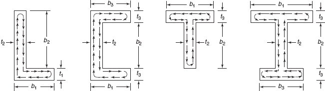
Figure 5.17 Example 5.6
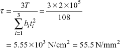
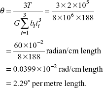
Example 5.6 An I section with flanges 10 cm × 2 cm and web 28 cm × 1 cm is subjected to a torque = 2 kNm. Find the maximum shear stress and angle of twist per unit length. G = 80,000 N/mm2.
Solution: |
G = 8 × 10⁴ N/mm2 = 8 × 10⁶ N/cm2 |
Torque |
T = 2 kNm = 2 × 10⁵ N cm |
2 Flanges, |
b = 10 cm, t = 2 cm |
1 Web |
b′ = 28 cm, t′ = 1 cm |
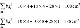
Maximum shear stress,
Angular twist per unit length,
Exercise 5.6 A T-section with flange 10 cm × 1 cm and web 19 cm × 0.8 cm is subjected to a torque of 200 Nm. Find the maximum shear stress and angle of twist per metre length. G = 82 kN/mm2
Ans.[27.08 N/mm2, 2.125°].
5.8 TORSION OF THIN WALLED MULTI-CELL SECTIONS
The analysis of thin walled closed sections can be extended to multi-cell sections. Consider a two cell section as shown in Figure 5.18. Say the shear flow in cell 1 is q1, in cell 2 it is q2 and in the web, shear flow is q3. Now consider the equilibrium of shear forces at the junction of the two cells, taking a small length δl, along the axis of the multi-cell section. The complementary shear stresses τ1, τ2, and τ3 are shown in the longitudinal sections of length δl each but thicknesses t1, t2, and t3, respectively. For the equilibrium along the direction of the axis of multi-cell tubular section:
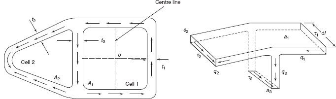
Figure 5.18 Multi cell sections
or τ1t1 = τ2t2 + τ3t3 (5.7)
or q1 = q2 + q3
shear flow, q1 = shear flow q2 + shear flow, q3.
This is equivalent to fluid flow dividing itself into two streams:
Shear flow in web, q3 = q1 – q2
Twisting moment T1 about O due to q1, flowing in cell 1.
where A1 = area enclosed by the centre line of cell 1.
Twisting moment T2 about O due to q2 in cell 2:
where 2 q2 A1′ is the twisting moment due to shear flow q2 in the middle web.
Total twisting moment,
T = T1 + T2
= 2q1 × A1 + 2q2 × A2 (5.10)
For continuity, the angular twist per unit length in each cell will be the same. For closed thin sections
But in this case shear flow is changing, therefore
Say
![]() for cell 1 including web
for cell 1 including web
![]() for cell 2 including web
for cell 2 including web
![]() for the web
for the web
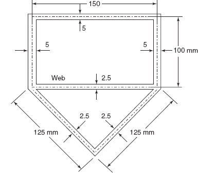
Figure 5.19 For example 5.7
For cell 1,
For cell 2,
From equations (5.11), (5.12), and (5.13), shear flow q1, q2, and angular twist θ can be worked out.
Example 5.7 Figure 5.19 shows the dimensions of a double walled cross-section in the form of a rectangle and a triangle. A torque of 4 kNm is applied. Calculate the shear stress in each part and the angle of twist per metre length. G = 82 kN/mm2.
Solution: Say shear flow in rectangular cell= q1 and shear flow in triangular cell = q2
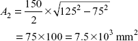
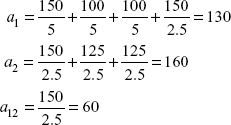
Area,
Area,
Line integrals,
Now torque
T = 2q1 × A1 + 2q2 × A2
4 × 10⁶ Nmm = 2 × 15 × 103 × q1 + 2 × 7.5 × 103 × q2 (i)
2000 = 15q1 + 7.5q2
But θ in cell 1 = θ in cell 2
So,
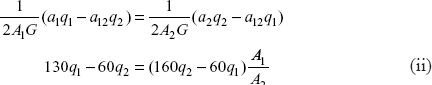
But
Substituting in Equation (ii), we get
or
Substituting in Eq. (i), we get
or shear flow
τ1, shear stress in rectangular part
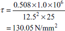
τ2, shear stress in triangular part
τ3, shear stress in web
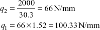
Exercise 5.7 A steel girder of the section is shown in Figure 5.20. It has uniform thickness of 12 mm throughout. What is allowable torque if maxm shear stress is not to exceed 30 MPa? What is the angular twist per metre length of girder? What is shear stress in middle web of section? G = 82 kN/mm2.
Ans. [20.74 N/mm2, 0.26°; No stress in middle web].
Problem 5.1 A shaft of rectangular section is subjected to a torque of 0.8 kNm and maximum permissible shear stress in the shaft is 40 N/mm2. If the ratio of breadth to depth is 1.5, determine the size of the shaft and the angle of twist in a length of 4m. G = 78.4 kN/mm2.
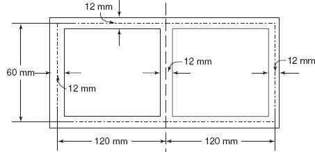
Figure 5.20 Problem 5.1
Solution:
Torque T |
= |
0.8 × 10⁶ Nmm = 800 × 103 Nmm |
Larger side |
= |
1.5 × shorter side |
b |
= |
1.5 a |
Maximum shear stress = 40 N/mm2
Moment of resistance,
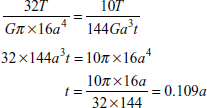
or
14.2857 a3 = 800 × 103 Nmm
a3 = 56 × 103 mm3
Shorter side, a = 38.2 mm
Longer side, b = 1.5 × 38.2 = 57.3 mm
Angle of twist
where

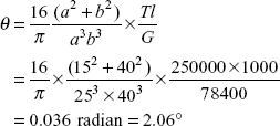
Problem 5.2 A shaft of elliptical section with major axis 40 mm and minor axis 25 mm is subjected to a twisting moment of 250 Nm. Determine the maximum shear stress developed in the shaft and the angle of twist in a length of 1 metre. G = 78400 N/mm2.
Solution:
Torque, T = 250 Nm = 250 × 1000 Nmm
Minor axis, a = 25 mm
Major axis, b = 40 mm
where τ is maximum shear stress at the edges of minor axis.
Angular twist,
Problem 5.3 A closed tubular section of mean radius R and radial thickness t and a tube of the same radius and thickness but with a longitudinal slit are subjected to the same twisting moment T. Compare the maximum shear stress developed in both and also compare the angular twist in these tubes.
Solution: Mean radius = R
Thickness = t
Closed Tubular Section (Figure 5.21)
Maximum shear stress
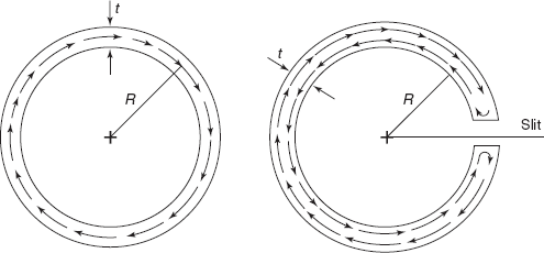
Figure 5.21 Problem 5.3
Angular twist per unit length
Tubular section with a small slit. This can be treated as a thin rectangular section of width 2πR and thickness t. (Figure 5.21)
Maximum shear stress, ![]()
Angular twist per unit length,
So, the closed tubular section is much more stronger and stiffer than the open tubular section with a slit.
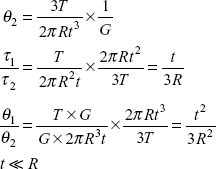
Problem 5.4 An extruded section of a light alloy is in the form of a semi-circle of mean diameter 8 cm and thickness 4 mm. If a torque is applied to the section and the angle of twist is limited to 4° in a length of 1 metre, estimate the torque and the maximum shear stress, G = 26000 N/mm2.
Solution: The semi-circular section having only one boundary can be treated as thin rectangular section of width πR and thickness t.
Width, b = π R = π × 40mm
Thickness, t = 4mm
Angular twist per mm,
Maximum shear stress,
Problem 5.5 An I section with flanges 50 mm × 5 mm and web 140 mm × 3 mm is subjected to a twisting moment of 0.2 kNm. Find the maximum shear stress and twist per unit length neglecting stress concentration. G = 80000 N/mm2.
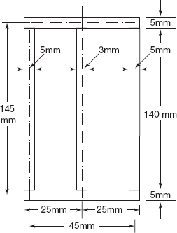
Figure 5.22 Problem 5.5
In order to reduce the stress and the angle of twist per unit length, the I section is reinforced by welding steel plates 140 mm × 5 mm as shown in Figure 5.22. Find the maximum stress due to the same twisting moment. What is then the value of angle of twist per unit length?
Solution:
I section
Flanges 50 × 5 mm
Web 140 × 3 mm
Maximum shear stress

Angular twist per unit length
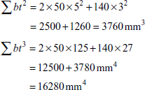
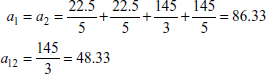
Reinforced I section. As shown in Figure 5.22, there are two cells of area
Line integrals
Say the shear flow in cell 1 is q1 and shear flow in cell 2 is q2. Then
T, Torque = 2q1A1 + 2q2A2
= (q1 + q2)(2 × 3262.5) = 6525(q1 + q2)
But A1 = A2
So, 86.33q1 − 48.33q2 = 86.33q2 − 48.33q1 or q1 = q2
Maximum shear stress ![]()
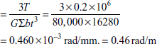
Angular twist per unit length

Problem 5.6 A shaft made of plastic is of elliptical cross-section as shown in Figure 5.23. If it is subjected to torsional loading as shown, determine shear stress at point A. Determine the angle of twist at the end B. Gplastic = 15 GPa.
Solution: T, Torque at the point A = 60 + 30 = 90 Nm = 90 × 103 Nmm
Semi-major axis of ellipse, b = 50 mm
Semi-minor axis of ellipse, a = 20 mm.
Shear stress at point A′ (end of the minor axis)
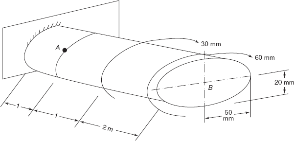
Figure 5.23 Problem 5.6
Torque for 2 m length, T1 = 60 Nm
Torque for another 2 m length, T2 = 60 + 30 = 90 Nm
Angular twist,
So,
Problem 5.7 A light alloy strut member of an aeroplane is 1.8 m long and has the cross-section as shown in Figure 5.24. If the maximum shear stress is limited to 36 N/mm2, determine the torque that can be sustained and the angular twist in the member. G = 28 GPa.
Solution: The area enclosed by the median line through the wall thickness of the section
A = π × 302 + 60 × = 6427.44mm2 |
|
Minimum wall thickness, |
t = 2 mm |
Allowable shear stress |
τ = 36 N/mm2 |
So, Allowable shear flow, |
q = t τ = 36 × 2 = 72 N/mm |
Allowable Torque, |
T = 2Aq = 2 × 6427.44 × 72 |
|
= 925551.36 Nmm = 925.55 Nm |
Length, |
l = 1.8 m = 1800 mm |
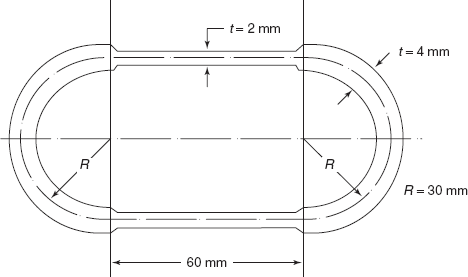
Figure 5.24 Problem 5.7
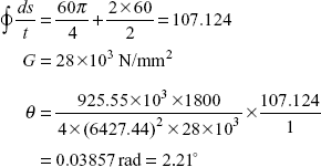
Angle of twist, ![]()
Line integral
Problem 5.8 A shaft section consists of a hollow rectangular section and a solid rectangular section as shown in Figure 5.25. Composite shaft is subjected to a twisting moment of 100 Nm. Determine (i) torque shared by hollow and solid section, (ii) maximum shear stress developed in both the sections, (iii) angular twist per m length in shaft if G = 25 × 103 N/mm2.
Solution:
Solid shaft
Angular twist per unit length
From tables

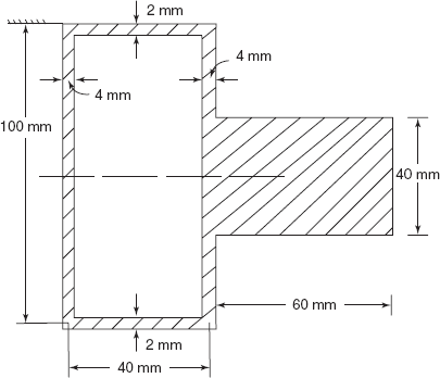
Figure 5.25 Problem 5.8
Hollow Shaft
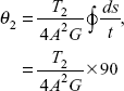
where A = 100 × 40 = 4000 mm2
But θ1 = θ2 because both portions twist simultaneously by the same amount.
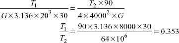
But
- T2 = 73.9 Nm, Torque shared by hollow portion.
T1 = 24.1 Nm, Torque shared by solid portion.
- Solid Shaft
Maximum shear stress,

where
Hollow Shaft
Shear flow,

- Angular Twist
G
=
25000 N/mm2
θ1
=
=
1.387 × 10⁻⁶ rad/mm
=
1.387 × 10⁻³ rad/m
=
0.08° = θ2 Angular twist in composite shaft over 1m length
MULTIPLE CHOICE QUESTIONS
- A shaft of rectangular section b × a (where b is longer than a) is subjected to a twist- ing moment. The maximum shear stress occurs
- at the ends of diagonals
- at the centre of larger side
- at the centre of smaller side
- None of these
- A shaft of elliptical section of major axis 2b and minor axis 2a is subjected to twisting moment. What is expression of its polar moment of inertia J?


- None of these
- In membrane analogy which one of the following is a wrong statement.
- Slope of the membrane at any point is proportional to the magnitude of shear stress at that point.
- Direction of shear stress at any point is along the tangent to the deflection contour at that point.
- Volume displaced by membrane is equivalent to the torque applied on non-circular shaft.
- None of these.
- A shaft of equilateral triangular section of side `a’ is subjected to twisting moment T. What is maximum shear stress developed in shaft section?


- None of these
- A shaft of thin square section with mean perimeter 16 cm and wall thickness 2.5 mm is subjected to a twisting moment 16 Nm. What is the maximum shear stress developed in shaft section?
- 2 N/mm2
- 4 N/mm2
- 8 N/mm2
- None of these
- A T-section flange 10 cm × 1 cm and web to 10 cm × 1 cm is subjected to a torque of 50 Nm. Maximum shear stress developed in section is
- 2.5 MPa
- 5 MPa
- 7.5 MPa
- None of these
- A thin circular section of mean radius R, wall thickness t is subjected to a twisting moment T, what is shear flow q in section?


- None of these
- A shaft is of hollow square section with outer side 52 mm and inner side 48 mm. If shear flow in shaft section is 10 N/mm, what is the torque applied on shaft?
- 52 Nm
- 50 Nm
- 25 Nm
- None of these
Answers
1. (b) |
2 (b) |
3 (c) |
4 (b) |
5 (a) |
6 (c) |
7 (a) |
8 (b) |
PRACTICE PROBLEMS
5.1. A thin rectangular steel section of outer dimensions 106 × 76 mm and inner dimensions 94 × 64 mm is subjected to a twisting moment such that the maximum shear stress developed in section is 35 MPa. If the length of the shaft of thin rectangular section is 2 m, determine (a) twisting moment in shaft and (b) angular twist. G = 84 kN/mm2.
Ans. [2.94 kNm, 0.58°].
5.2. A tubular circular section of mean radius 50 mm and wall thickness 5 mm is subjected to a twisting moment such that the maximum shear stress developed is 80 MPa. Another tubular square section of the same wall thickness and the same perimeter as those of the circular section is also subjected to the same twisting moment. Find the maximum shear stress developed in square section.
Ans. [101.86 MPa].
5.3. An extruded section of brass is in the form of a semi-circle of mean diameter 90 mm and thickness 4 mm. If a torque of 5 Nm is applied to the section, determine the maximum shear stress developed in the section. What is the angular twist per meter length? G for brass = 39 kN/mm2.
Ans. [4.63 MPa, 2.435°].
5.4. A thin walled box section has two compartments as shown in Figure 5.26. The thickness of the section is constant. What is the shear stress in both the cells? Take a = 10 cm, t = 8 mm. What will be the angular twist per unit length if G = 80 kN/mm2? Torque applied on shaft is 400 Nm.
Ans.[2.484, 0.397 MPa, 0.036°/mm].
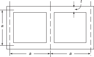
Figure 5.26 Problem 5.4
5.5. A steel shaft 35 cm long is screwed into the wall using a wrench as shown in Figure 5.27. Determine the largest force F that can be applied on the wrench without causing the stress to reach. τ = 130 N/mm2. Shaft is of square section 25 × 25 mm.
Ans. [8463.5 N].
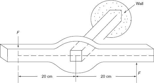
Figure 5.27 Problem 5.5
5.6. For a given maximum shear stress, determine the factor by which the torque carrying capacity is increased if the half circular section is reversed as shown in Figure 5.28. The tube is 3 mm thick
Ans. [1.71]
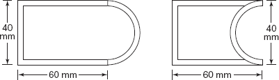
Figure 5.28 Problem 5.6
5.7. A tube is made from high strength steel sheet 5 mm thick having the mean dimension shown in Figure 5.29. It is subjected to a torque of T = 100 Nm, determine the average shear stress developed at points A and B.
Ans. [τA = τB = 0.893 MPa].

Figure 5.29 Problem 5.7
5.8. A steel tube has an elliptical cross-section of mean dimensions major axis = 2a, minor axis = a, constant thickness 4 mm as shown in Figure 5.30. If the allowable shear stress is 30 N/mm2 and the tube is to resist 360 Nm, determine the necessary dimension a.
Ans. [15.45 mm].
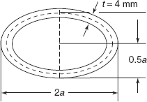
Figure 5.30 Problem 5.8
5.9. Compare the torsional strength and stiffness of thin walled tubes of circular section of mean radian R and thickness t with and without a longitudinal slot.
Ans. ![]()
5.10. A torque of 200 Nm is applied to the tube shown. If the wall thickness is 2.5 mm, determine the maximum shear stress in the tube. (Figure 5.31)
Ans. [25.15 MPa].
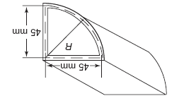
Figure 5.31 Problem 5.10
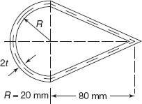
Figure 5.32 Problem 5.11
5.11. For a light aircraft, the cross-section of a strut is shown in Figure 5.32. The strut is made of light aluminium alloy. The length of the strut is 3 m. If the shear stress in the strut is not to exceed 30 MPa, and the applied torque is 134 Nm, determine the value of thickness t of metal. What is the angle of twist? G = 28000 N/mm2.
Ans. [1 mm; 8.14°].