

7
CONTROLLING THINGS WITH ELECTRICITY
Electronic components let you build smart things, like a lamp that turns on when it gets dark or a door that opens automatically when you approach it. In this chapter, you’ll learn about a new component that will help you build such smart objects: the transistor.
The previous chapter showed you how to solder, and this chapter’s projects—a touch sensor and an alarm that wakes you up when the sun rises—will give you more chances to practice your soldering skills. All you need for each project is the transistor and a few additional components.
MEET THE TRANSISTOR
The transistor is the most important component in electronics, and if you’ve ever heard experienced hardware enthusiasts talk about it, you’ve probably noticed that they tend to use a lot of difficult words. But the transistor really isn’t hard to understand; in fact, you’ve already used something that acts a lot like one! Do you remember the relay you learned about in Chapter 5? The transistor is similar to the relay in many ways: it’s like a switch that you can open and close with electricity.

A transistor has three legs. In a standard NPN transistor, the three legs are called emitter, base, and collector. You’ll often see these labeled e, b, and c in circuit diagrams. You turn the transistor on and off—that is, you open and close the switch—with the base and emitter legs, and you connect a circuit that you want to control between the collector and the emitter legs.
When you look at our example transistor with the flat side facing you, the leftmost leg is the emitter, the middle leg is the base, and the rightmost leg is the collector. But this is not the case for all transistors, so always check the datasheet for your transistor to find out which leg is which.
Why Use a Transistor?
If a transistor acts like a switch, then you might be wondering when you’d want to use a transistor instead of a switch in the first place. Well, think about a fan: if it’s hot in your room and you want to turn a fan on, you have to manually flip a switch. But if that fan were part of the right kind of circuit with a transistor and a few other components, you could make the fan turn on automatically when the temperature in your room rises above 75 degrees Fahrenheit. To make this happen, you’d need one circuit that could sense temperature and another circuit that could turn on a fan.
Now, imagine a temperature-sensing circuit that gives a voltage when the temperature is above 75 degrees and no voltage if the temperature is below. If you were to connect one wire from the fan to an NPN transistor’s collector, connect the fan’s other wire to the positive terminal of the battery, and connect the transistor’s emitter to the battery’s negative terminal, the transistor would control when the fan is switched on.

Then, you could connect the output of the temperature-sensing circuit to the controlling part of the transistor—that is, the base and emitter. In such a circuit, the fan would turn on when the temperature rises above 75 degrees and turn off when the temperature is less. Let’s look at how the transistor’s “switch” closes in the first place.
How the Transistor Works
When a little bit of current flows from the base of a transistor to the emitter, the transistor “closes the switch” so that current can also flow from the collector to the emitter.

In Chapter 1, I explained that voltage pushes current through a circuit. For current to flow from the base to the emitter, there needs to be a voltage to push that current. When the current flows from the base to the emitter, this opens a path for the current to flow between the collector and the emitter. You can also control the amount of current that flows between the collector and the emitter by changing the current flowing from the base to the emitter.
The specific type of transistor we’re talking about is an NPN-type bipolar junction transistor. This long name describes the materials inside the transistor. There’s some advanced chemistry and physics behind how it works, but you don’t need to know all of that to build cool circuits with a transistor—you just need to know what the transistor does.
The important thing to remember for now is that different transistor types exist. For each transistor project in this book, just use the type I describe in the Shopping List sections, and your circuits will work just fine. And of course, when you build circuits outside this book, be sure to use the type of transistor specified in the circuit diagram.
Controlling an LED with a Transistor
Other projects in this book have used this simple LED circuit, complete with a resistor and a battery:

Based on what you’ve learned so far, what do you think would happen if you put a transistor between the resistor and the battery’s negative terminal?

With no voltage on the transistor’s base, or the controlling pin, no current flows from the base to the emitter. That means no current can flow between the collector and the emitter either, and the LED would be off.
But if you were to apply a small voltage to the base—for example, by connecting a small battery to it—the transistor would let current flow from the collector to the emitter, and the LED would glow. A transistor that allows current to pass is considered on; a transistor that doesn’t allow current to pass is considered off. The amount of voltage needed to turn an NPN transistor on is about 0.7 V, so a circuit like this one would allow current to pass through properly to light the LED:

Normally, you wouldn’t connect a battery to the base. Instead, you’d connect another circuit that you want to control the transistor, like a light-sensing circuit that gives a small voltage when it detects light. A circuit like that would turn the transistor on and off according to the light.
You can build a circuit like this to control LEDs and other components. In the next project, I’ll show you how to use a transistor to turn an LED on with the touch of your finger.
PROJECT #14: BUILD A CIRCUIT THAT SENSES TOUCH
Did you know that your finger can act as a resistor? Your finger has a resistance of a few megohms (MΩ), and that’s a lot! This resistance varies, though. If your finger is sweaty, for example, the resistance decreases.
In this project, you’ll use your finger as a resistor to complete a circuit that turns on an LED, creating a touch sensor. A sensor is a component that can measure things in the world around you, like light or temperature. In many cases, a sensor is a resistor that changes its value based on light level, temperature, or some other physical quantity you might want to know about.
If you connect a resistor of a few megohms between the positive side of your battery and the base of the transistor in this circuit, a small current should flow through the base of the transistor to the emitter. This current should be large enough to turn the transistor on and let a little bit of current flow from collector to emitter.
This circuit has a transistor, a resistor, an LED, and a battery, just like the one in the previous section. This time, instead of a separate battery, you’ll connect the 9 V battery to the transistor’s base with your finger through a kind of touch pad. The touch pad will just be two exposed wires placed close enough together that you can touch both with your finger at the same time.

Notice that instead of a 330 Ω resistor with the LED that you used before, this circuit uses a 100 Ω resistor. Often the resistance in your finger is so high that the transistor won’t turn on fully. With a smaller resistor, you should still get a bright LED, even if your finger’s resistance is a bit high.
Shopping List

![]() A standard 9 V battery to power the circuit.
A standard 9 V battery to power the circuit.
![]() A 9 V battery clip (Jameco #11280, Bitsbox #BAT033) to connect the battery to the circuit.
A 9 V battery clip (Jameco #11280, Bitsbox #BAT033) to connect the battery to the circuit.
![]() A circuit board (Jameco #2191488, Bitsbox #HW005) with copper strips.
A circuit board (Jameco #2191488, Bitsbox #HW005) with copper strips.
![]() A standard LED (Jameco #34761, Bitsbox #OP003)
A standard LED (Jameco #34761, Bitsbox #OP003)
![]() Two pieces of exposed wire, each about 1 inch long. You could also use two legs you cut from components in other projects.
Two pieces of exposed wire, each about 1 inch long. You could also use two legs you cut from components in other projects.
![]() A transistor 2N3904 (Jameco #38359, Bitsbox #QD018)
A transistor 2N3904 (Jameco #38359, Bitsbox #QD018)
![]() A 100 Ω resistor (Jameco #690620, Bitsbox #CR25100R) for limiting the current to the LED.
A 100 Ω resistor (Jameco #690620, Bitsbox #CR25100R) for limiting the current to the LED.
Tools

![]() A soldering iron (for example, Jameco #116572, Bitsbox #TL031)
A soldering iron (for example, Jameco #116572, Bitsbox #TL031)
![]() A stand (for example, Jameco #36329, Bitsbox #TL032) to hold the soldering iron.
A stand (for example, Jameco #36329, Bitsbox #TL032) to hold the soldering iron.
![]() Solder wire (for example, Jameco #94570, Bitsbox #HW022)
Solder wire (for example, Jameco #94570, Bitsbox #HW022)
![]() A multimeter (Jameco #2206061, Bitsbox #TL057, Rapid Electronics #55-6662) to measure voltages if the circuit doesn’t work.
A multimeter (Jameco #2206061, Bitsbox #TL057, Rapid Electronics #55-6662) to measure voltages if the circuit doesn’t work.
![]() A wire cutter (Jameco #35482, Bitsbox #TL008) to cut off excess legs.
A wire cutter (Jameco #35482, Bitsbox #TL008) to cut off excess legs.
Step 1: Place Components on the Prototyping Board
Place the LED, the resistor, and the transistor into the prototyping board as shown. Make sure a copper strip connects the resistor to (1) the LED’s cathode leg and (2) the transistor’s collector leg. Bend the legs on the copper side of the board so that the components stay in place.

Step 2: Check Your Component Placement
Before soldering, look on the copper side of the board and double-check that your components are placed according to the directions in Step 1. Inspect the orientation of the LED and the transistor specifically, as these must be soldered the correct way for your circuit to work.
Step 3: Solder the Components and Trim Excess Legs
Solder the components to the board, just as you learned in “How to Solder” on page 112, and then use your wire cutters to cut off the excess legs. Wear your safety goggles and take care to turn the board away from yourself in case bits of wire fly off as you cut.

Step 4: Solder the Touch Pad
Next, solder the two pieces of exposed wire. Connect one wire to the LED’s anode leg, with the other end on an empty copper strip. Connect the other wire to the base of the transistor, also with the other end on an empty copper strip. Solder them in such a way that you can touch both with your finger.

Step 5: Power It Up!
Now you need power! To finish the job, first solder the battery clip to the board, placing the red and black wires as shown at ➊. After you’ve soldered the battery clip, plug the battery into it at ➋.

This touch-sensor circuit is ready to test!
Step 6: Test the Sensor
Touch both exposed wires at the same time with your finger. Your LED should light up. If you can’t see the LED glow, try turning out the light in your room; the LED might just be dim. If you still can’t see the LED glowing, dip your finger in water and try again, as wetting your finger reduces its resistance.
WARNING
Use only a finger to touch the exposed wires. If you use something with a very low resistance, like a piece of wire, you can destroy the transistor.
Step 7: What If the Touch Sensor Doesn’t Work?
If nothing happens when you touch the wires, start by checking the direction of your LED and your transistor. It’s very common to mix up the pins of these components, so go back to Step 1 and make sure they’re connected on the prototyping board’s copper strips, according to the images.
If the LED and the transistor are connected correctly, you can use your multimeter to measure the voltage between the base and the emitter of the transistor on the controller side, without touching the touch pad. Set your multimeter to a DC voltage range—20 V DC, for example—and then connect one multimeter cable to the base leg and one to the emitter leg, as shown. The multimeter should show a value around 0 V. Now, place your finger on the touch pad and measure the voltage again. The multimeter should show around 0.7 V.

If the controller side of the transistor is fine, check the switch side. Measure the voltage from one leg of the LED to the other, without touching the touch pad. You should see 0 V on the multimeter. Place your finger on the touch pad and measure again; now it should be around 1.7 to 2 V.
If either multimeter measurement gives you incorrect values, then check your connections against the circuit diagram one more time, paying extra attention to the two exposed wires. Finally, check your solder joints, look for stray pieces of wire or solder bridging the gap between copper strips, and fix any bad connections you find.
RESISTORS THAT CAN CHANGE VALUE
Up until now, you’ve used only resistors that have a fixed resistance, but you can also find resistors that have a variable resistance value, which means the resistance can change. For example, some resistors change value when you turn a knob, while others change their value based on the temperature or the amount of light. This section introduces two variable resistors: the potentiometer and the photoresistor.
Meet the Potentiometer
In Chapter 4, you learned about the standard resistor, a component that has a certain, unchangeable resistance. The potentiometer is also a resistor, but it has a variable resistance, and it’s often used to control things such as the volume of a speaker. (You know the volume control on the radio? That’s often a potentiometer.) A potentiometer usually has three pins and a shaft you can rotate to change the resistance.

The potentiometer symbol represents how the potentiometer works and the functions of the three pins. The resistance between pins 1 and 3 is a fixed resistance of a certain value. This value is equal to the value listed when you buy the potentiometer. If you have a 10 kΩ potentiometer, for example, then the resistance between pins 1 and 3 will be 10 kΩ.
Pin 2 is called the wiper. It connects to the resistor somewhere between pins 1 and 3. You can change the position of the wiper by turning the shaft of the potentiometer. If you turn the shaft so that the wiper comes closer to pin 1, the resistance between pin 1 and the wiper gets smaller, but the resistance between pin 3 and the wiper becomes larger.
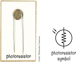
Meet the Photoresistor
A photoresistor is another variable resistor. Photo means light, and this component’s resistance changes with the amount of light shining on the top of it. Sometimes this component is also called a light-dependent resistor (LDR) because its value depends on light.
Photoresistors are made of a material with some special properties. In the dark, this material has a high resistance, but when light shines on it, the light energizes electrons that would otherwise be bound in the material. Those energized electrons can flow freely through the material, reducing the resistance. The more light that shines on the photoresistor, the less resistance it has.
DIVIDING A VOLTAGE WITH RESISTORS
When the resistance of a photoresistor or potentiometer in a circuit changes, the voltage and/or the current must change, too, according to Ohm’s law. (See “Introducing Ohm’s Law” on page 73 if you want to walk through the math again.) If you make your variable resistor part of a circuit called a voltage divider, you’ll get a voltage output that varies with the resistance. You can use that changing voltage to control another component in your circuit. Knowing how to identify voltage dividers can also help you understand how other circuits work.
What Does a Voltage Divider Look Like?
If you connect two resistors with the same resistance to each other and to the positive and negative sides of a battery, the voltage where your resistors meet will be half the battery voltage—for example, 4.5 V if you use a 9 V battery. This circuit is called a voltage divider.

If you use unequal resistors instead of identical ones, you can use a voltage divider to get voltages anywhere from 0 V up to your battery voltage. You just need to do a little bit of math.
Calculating the Voltage from a Voltage Divider
Let’s say you have the following circuit. What’s the output voltage (Vout) from this circuit?
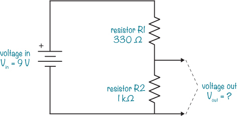
To find Vout, enter the values from the circuit into the following formula:

In this example, the output voltage is 6.77 V—roughly two-thirds of the 9 V input from the battery.
How a Voltage Divider Can Help Measure Light
In the beginning of this section, I mentioned that the voltage divider can help you measure light, but how do you do that? Just replace one resistor in the voltage divider with a photoresistor, and you’ll get a circuit that outputs a voltage based on the amount of light shining on it. And by adjusting the other resistor in the voltage divider, you can set the circuit to give a certain voltage at a certain light level. Connect the output of this circuit to a transistor that controls a buzzer, and you’ve got yourself a light-controlled alarm!
PROJECT #15: BUILD A SUNRISE WAKE-UP ALARM
It’s time to combine all the concepts you’ve learned in this chapter into one fun project: a sunrise wake-up alarm!
This circuit starts an alarm when it detects light. After you build it, you can place it in your window (between any curtains and the glass) when you go to bed. When the sun rises, your circuit should detect the light and start the alarm, leaving you with no choice but to get up and turn it off.

This project uses a transistor, a photoresistor, a potentiometer, and a buzzer. The photoresistor and the potentiometer create the voltage divider, and the output of the voltage divider is connected to the base of the transistor. The amount of light the photoresistor detects will determine whether the transistor is on or off. If the transistor is on, current should flow through the buzzer, and the buzzer should make sound. The potentiometer is there to set how much light the circuit needs before the alarm triggers.
Shopping List

![]() A standard 9 V battery to power the circuit.
A standard 9 V battery to power the circuit.
![]() A 9 V battery clip (Jameco #11280, Bitsbox #BAT033) to connect the battery to the circuit.
A 9 V battery clip (Jameco #11280, Bitsbox #BAT033) to connect the battery to the circuit.
![]() A circuit board (Jameco #2191488, Bitsbox #HW005) with copper strips.
A circuit board (Jameco #2191488, Bitsbox #HW005) with copper strips.
![]() Insulated wire (Jameco #36792, Bitsbox #W106BK), about 10 inches in length. Standard hookup wire works fine.
Insulated wire (Jameco #36792, Bitsbox #W106BK), about 10 inches in length. Standard hookup wire works fine.
![]() A transistor 2N3904 (Jameco #38359, Bitsbox #QD018)
A transistor 2N3904 (Jameco #38359, Bitsbox #QD018)
![]() A 10 kΩ potentiometer (Jameco #2118791, Bitsbox #VR004)
A 10 kΩ potentiometer (Jameco #2118791, Bitsbox #VR004)
![]() A photoresistor (Jameco #202454, Bitsbox #ST004) for detecting light.
A photoresistor (Jameco #202454, Bitsbox #ST004) for detecting light.
![]() A buzzer (Jameco #2173870, Bitsbox #ST016) that beeps. Buzzers come in both active and passive versions. You’ll need an active buzzer that works with 9 V in this project, just like the one you used in “Project #2: Intruder Alarm” on page 11.
A buzzer (Jameco #2173870, Bitsbox #ST016) that beeps. Buzzers come in both active and passive versions. You’ll need an active buzzer that works with 9 V in this project, just like the one you used in “Project #2: Intruder Alarm” on page 11.
Tools

![]() A soldering iron (for example, Jameco #116572, Bitsbox #TL031)
A soldering iron (for example, Jameco #116572, Bitsbox #TL031)
![]() A stand (for example, Jameco #36329, Bitsbox #TL032) to hold the soldering iron.
A stand (for example, Jameco #36329, Bitsbox #TL032) to hold the soldering iron.
![]() Solder wire (for example, Jameco #94570, Bitsbox #HW022)
Solder wire (for example, Jameco #94570, Bitsbox #HW022)
![]() A multimeter (Jameco #2206061, Bitsbox #TL057, Rapid Electronics #55-6662) to measure voltages if the circuit doesn’t work.
A multimeter (Jameco #2206061, Bitsbox #TL057, Rapid Electronics #55-6662) to measure voltages if the circuit doesn’t work.
![]() A wire cutter (Jameco #35482, Bitsbox #TL008) to cut off excess legs.
A wire cutter (Jameco #35482, Bitsbox #TL008) to cut off excess legs.
Step 1: Place Components on the Prototyping Board
Start by placing the transistor, the photoresistor, and the potentiometer on the board, as shown. Bend the legs of the photoresistor and transistor on the other side so that they stay in place. The top copper strip will be the positive battery connection, and the bottom copper strip will be the negative one.

The diagram shows the components and the copper tracks underneath, while the photo shows what your board should look like in real life.
Step 2: Solder the Components and Trim the Legs
Check the placement of the components closely against the circuit diagram at the beginning of the project and the illustration in Step 1. Make sure the transistor is connected the right way and that the photoresistor has one leg on the same copper row as the center pin of the transistor. Each of the other pins, including each pin on the potentiometer, should be on a row of its own.
When you’re sure your components are placed correctly, solder the pins to the board.

When you’re finished soldering, cut off the excess legs.
Step 3: Add the Buzzer to the Board
Next, solder the buzzer to the board. Place the buzzer’s positive (red) lead through a hole in the top copper row together with the photoresistor. Then place its negative (black) lead in the same row as the collector leg of the transistor. Solder both now.

Step 4: Make the Remaining Connections with Wires
If you compare your circuit to the circuit diagram, you’ll see that you’re still lacking a few connections to make the circuit complete. The circuit board is missing the battery clip, but to work when powered, the circuit also needs the following connections:
![]() The base of the transistor needs to connect to the upper potentiometer pin.
The base of the transistor needs to connect to the upper potentiometer pin.
![]() The middle potentiometer pin needs to connect to the negative battery terminal.
The middle potentiometer pin needs to connect to the negative battery terminal.
![]() The emitter of the transistor needs to connect to the negative battery terminal.
The emitter of the transistor needs to connect to the negative battery terminal.
To create these remaining connections, you can solder three small wires like this one to the circuit board as jumper wires:

Cut a piece of wire about 2 inches long and strip about 0.3 inches of insulation from both ends. Removing insulation from shorter wires can be tricky, so if you’re struggling with this step, use a longer wire instead. When you know what length of wire you can strip most easily, prepare two more wires. Then, solder the three wires to make the remaining connections.
Run one wire from the base of the transistor to the upper pin of the potentiometer. Next, connect the one wire from the middle pin of the potentiometer to an empty row at the bottom of the board. Finally, run one wire from the same row of the prototyping board, where you just connected the previous wire, to the row connected to the emitter of the transistor. Check that your wires match the illustration and then solder them to the board.

Step 5: Add the Battery Clip to the Board
All that’s missing is the battery clip. Solder the battery clip’s red wire to the top copper row of the board. The top row should also contain the photoresistor leg and the buzzer’s red wire. Solder the battery clip’s black wire to the bottom row.

Step 6: Set a Wake-Up Call
Plug in the battery and put the circuit in an area that has the amount of light that you want to activate your alarm. Turn the shaft of the potentiometer until you find a position where the sound turns on and off with just a little nudge back and forth on the shaft. Now, turn the shaft just enough to make the sound turn on all the way. Place your hand over the photoresistor to block the light, and the sound should stop. Remove your hand, and the sound should turn on again.
Remove the battery from the circuit and wait until you’re about to go to bed. With the lights off, place the circuit in your window, connect the battery, and go to sleep. When the sun rises and the light outside is as bright as the light you used to set your potentiometer, you’ll be awakened by your very own sunrise alarm!
Step 7: What If There’s No Sound?
Go through the circuit component by component, preferably with a friend. Check that your prototyping board has every connection shown in the circuit diagram. Check that there are no short circuits, too. A short circuit is an unintentional connection between something in a circuit. For example, make sure solder joints that are close to each other aren’t actually touching.
If all looks good, use your multimeter to measure the voltage between the base and the emitter of the transistor. First, turn the shaft of your potentiometer all the way to one side, measure the voltage, and write it down. Then, turn the potentiometer all the way to the other side and measure the voltage again. Your multimeter should show 0 V on one side and around 0.7 V on the other side. If it doesn’t, check your connections again.
If you’re still not sure what’s wrong, turn the potentiometer all the way to one side and measure the voltage between the red and black buzzer wires. Then, turn the potentiometer all the way to the other side and measure again. You should get 0 V on one side and about 8 to 9 V on the other.
If all else fails, check your solder joints and redo any that look like the connections might not be complete. And if you’ve built your circuit flawlessly, you may just have some broken components. Try breadboarding the project with new components, and if that works, solder those components instead.
You can use the circuit you built in Project #15 for other things as well. For example, if you exchange the photoresistor for a thermistor, a resistor that changes resistance value based on temperature, the circuit will respond to temperature instead of light.
You can also change what’s being controlled. Instead of an LED and resistor, try putting in a fan. Now you have a temperature-controlled fan! The circuit diagram looks like this:

You’ll need the following parts:
![]() A standard 9 V battery to power the circuit.
A standard 9 V battery to power the circuit.
![]() A 9 V battery clip (Jameco #11280, Bitsbox #BAT033) to connect the battery to the circuit.
A 9 V battery clip (Jameco #11280, Bitsbox #BAT033) to connect the battery to the circuit.
![]() A circuit board (Jameco #2191488, Bitsbox #HW005) with copper strips.
A circuit board (Jameco #2191488, Bitsbox #HW005) with copper strips.
![]() Insulated wire (Jameco #36792, Bitsbox #W106BK), about 10 inches in length. Standard hookup wire works fine.
Insulated wire (Jameco #36792, Bitsbox #W106BK), about 10 inches in length. Standard hookup wire works fine.
![]() A 10 kΩ thermistor (Jameco #207037, Bitsbox #ST021)
A 10 kΩ thermistor (Jameco #207037, Bitsbox #ST021)
![]() A 10 kΩ potentiometer (Jameco #2118791, Bitsbox #VR004)
A 10 kΩ potentiometer (Jameco #2118791, Bitsbox #VR004)
![]() A transistor PN2222A (Jameco #178511, Bitsbox #QD101)
A transistor PN2222A (Jameco #178511, Bitsbox #QD101)
![]() A 12 V DC fan (Jameco #1708465, Bitsbox #AF002)
A 12 V DC fan (Jameco #1708465, Bitsbox #AF002)
For this circuit, I’ve specified a different transistor. Different transistors can handle different amounts of current. A fan often draws much more current than the LED, so I’ve listed a transistor that can handle more current than the one you used previously.
To test the circuit, first use an ice cube to cool down the thermistor and then warm it up with your fingers to see the fan come on.