

10
CIRCUITS THAT MAKE CHOICES
Chapter 9 was all about ones and zeros, and you played with bits and bytes in a couple of projects. Now in this chapter, you’ll make circuits that actually use ones and zeros to make decisions. Logic gates are components that check for the voltages that represent those ones and zeros and output a voltage accordingly. I’ll show you a few types of logic gates and how you can use them to create a secret code detector.
IT’S ONLY LOGICAL
Logic is a way of reaching a conclusion based on pieces of information that you know to be true or false. For example, imagine you know the following statement is true, beyond a doubt:
Statement 1: If there are oranges in your fridge AND you have an orange squeezer, THEN you’re able to make orange juice.
If you trust the preceding statement, then there are two conditions to check before you can make orange juice:
Condition 1: There are oranges in your fridge.
Condition 2: You have an orange squeezer.
If you check your kitchen and find that these conditions are true, then you can logically conclude that you can make orange juice.
Computers use Boolean logic, which is a system of logic that works only with the values true and false to convert ones and zeros into actions. For a computer to know whether you can make orange juice or not, it would have to reach that conclusion through Boolean logic. Let’s try thinking like a computer!
First, look for the conditions in Statement 1 that affect whether you can make orange juice or not. In this case, the conditions are the two phrases between “if” and “then,” joined by “and.” Assign them letters as follows:
There are oranges in your fridge. = A
You have an orange squeezer. = B
The conclusion is the statement after “then.” Give it a letter, too:
You’re able to make orange juice. = Q
With these letters, you could rewrite Statement 1 as “If A and B, then Q.” In Boolean logic shorthand, that looks like this:
A AND B = Q
This is a logic equation, where AND is an operator like addition or subtraction. When both statements on either side of AND are true, the conclusion Q is true.
Given Condition 1 and Condition 2, A and B are both true. Substitute both into the equation to get:
True AND True = Q
Q = True
Because both A and B are true, then Q must be true. Time to make orange juice!
How a Computer Decides When It Can Make Orange Juice
Condition A (There are oranges in your fridge.) |
Condition B (You have an orange squeezer.) |
Result Q (You’re able to make orange juice.) |
False |
False |
False |
False |
True |
False |
True |
False |
False |
True |
True |
TRUE! |
MEET THE LOGIC GATES
Many of the circuits inside your computer are physical versions of logic equations, complete with smaller circuits called logic gates, which are physical logical operators. A logic gate takes ones and zeros—representing true and false, respectively—as inputs and then outputs a 1 or 0 based on the results of the equation inside.
You can make really awesome projects with logic gates yourself, too!
I remember the first time my dad told me about logic gates: I went straight to my room and spent hours trying to combine them on paper in different ways to add binary numbers. I hope you have as much fun with them as I did! Now, let’s look at how a few different logic gates work.
AND Gates Check for Two True Inputs
The AND gate is the physical form of the AND operator you used to decide whether you were able to make orange juice. An AND gate has two or more inputs—A and B, for example—and one output—Q, for example. It checks whether A and B are both 1, and if they are, then Q is 1; otherwise, the output is 0. Q is 1 only if both A and B are 1; if one or both inputs are 0, the output is 0.
I find it helpful to write out the values of Q that result from different input combinations in a truth table. This truth table shows all possible input combinations for the AND gate and what the output will be for each. In a truth table, 0 stands for false, and 1 stands for true.

OR Gates Check for One True Input
The OR gate checks whether input A or input B is 1. If either is 1 or both are 1, then the output Q is also 1. But if both inputs are 0, then the output is 0.

NOT Gates Flip Inputs
The NOT gate, also called an inverter, has only one input and one output, and its function is very simple: the output is the opposite of the input. If the input is 1, then the output is 0. If the input is 0, the output is 1.

A Bigger AND Gate
AND gates and OR gates can have more than two inputs. For example, here’s a 4-input AND gate symbol:

Because it’s an AND gate, the result will be 1 only if all four inputs are 1; otherwise, it will be 0. That is, the output Q is true (1) if all four inputs—A, B, C, and D—are true (1):
Q = A AND B AND C AND D
We can also make a 4-input AND gate from three 2-input AND gates, like this:

HOW TO DRAW LOGIC CIRCUIT DIAGRAMS
You can use logic gates to build a circuit that checks for conditions and decides what to do based on them. For example, imagine you could deactivate your alarm system from Chapter 1 by entering a secret code. Then, you could leave the alarm system on while you’re gone, and if someone opened the door, they’d have to know the right code to turn the alarm off. With logic gates, a circuit can check easily whether the right code was entered.
A Logic Equation for a Secret Code
Let’s say the secret code is 1001, and when the secret code is detected, an LED should turn on to indicate success. When building logic circuits, it’s helpful to write the logic equation for your circuit before building, so let’s practice.
First, think about what each 1 and each 0 in the secret code represents in terms of logic gates. In this case, you want the LED to turn on only when four conditions are true, and you can connect those conditions with AND operators as follows.
Let’s represent the four bits in the secret code with the letters W, X, Y, and Z. Then, you can check each bit to see whether it’s the correct value, testing for W = 1, X = 0, Y = 0, and Z = 1.
You’ll need to AND the four secret code bits together using a 4-input AND gate. But simply connecting W, X, Y, and Z straight to the AND gate would give this logic equation:
Q = W AND X AND Y AND Z
This would test whether all the bits are 1 because Q = 1 only if W, X, Y, and Z are all 1. Instead, you need to test for the secret code where W and Z are 1, but X and Y are 0.
Fortunately, in Boolean logic, you have only two options: 1 or 0 (true or false). If something is 0, then it is NOT 1; in words, if something is false, then it is NOT true. This means that if X = 0 (false), then NOT X = 1 (true). Knowing that, you can rewrite the equation as follows:
Q = W AND (NOT X) AND (NOT Y) AND Z
This equation uses NOT on bits X and Y, which should be 0 for the secret code. The NOT will invert their values, changing 0 to 1 and 1 to 0.
Converting a Logic Equation into a Circuit Diagram
Now we’ll draw the secret code equation as a circuit. The final output will be a single 1 or 0. You need a 4-input AND gate to test all four code bits at once, and you’re going to make this using three 2-input AND gates as explained earlier. Because you need to test whether the X and Y bits are 0, you’ll need to use a NOT gate for each to invert the 0 to 1.
Here’s the final circuit:

The first bit (W) should be a 1 and the second (X) should be a 0, so the second bit gets a NOT gate. The third bit (Y) has a NOT gate as well, and it goes into an AND gate with the fourth bit (Z).
The first AND gate should output 1 if it sees W = 1 and X = 0, and the second AND gate should output 1 if it sees Y = 0 and Z = 1. If both of those AND gates output 1, then so will the third AND gate, which ultimately confirms that 1001 was entered.
USING LOGIC GATES IN REAL LIFE
When I learned about logic gates, I thought they’d be small two- and three-legged components. But logic gates come boxed inside integrated circuits (ICs). Each IC contains several gates, so even if you want to use just one, you’ll have to use an IC anyway.

It’s also important to know that logic gate outputs don’t supply much current. Even if a logic gate outputs 5 V, that doesn’t mean that you can connect your 5 V motor to it. The logic gate simply can’t give enough current for the motor to run.
Recall from Chapter 7 that a transistor needs only a little current flowing into its base to turn on and let a lot more current flow from its collector to emitter. When you want to use a logic gate to turn on a circuit or component that requires more current, you can connect the logic gate to a transistor. Do you remember the circuit from “Project #14: Build a Circuit that Senses Touch” on page 136? You can modify this circuit to turn on an LED from a logic gate, like this:

I’ll show you how to incorporate this into a project in the next section.
You can easily replace the LED and resistor with something else that you want to control, like a motor, a fan, or a relay. But when doing this, be mindful of the current. How much current does your motor need, and how much current can the transistor handle?
Both values can be found in the components’ datasheets. For transistors, the value you are looking for is called IC, or collector current. According to the datasheet of a BC547 transistor, its maximum collector current is 100 mA. That’s more than enough to power an LED, which usually uses about 15 to 20 mA at the most.
But what if you want to connect a motor? First, you’d need to find out how much current the motor needs, and you’ll find that in the motor’s datasheet. If a motor needs 500 mA, you’ll need to connect it to a transistor that can handle more than 500 mA of current. For example, a PN2222 transistor can handle up to 600 mA, so it should be able to switch the motor on and off.

PROJECT #21: A SECRET CODE CHECKER
In this project, you’ll build a logic circuit that checks whether a set of four input bits matches a secret code. You’ll use four switches, inside one DIP switch, to set the code. If the input bits match the code, then the logic circuit should output a voltage, representing a 1; otherwise, it should output zero voltage, to indicate 0. This final output will go to a transistor so you can use it to control something—like an alarm!

The basic Secret Code Checker circuit turns on an LED when you input the right code. At the end of the project, I’ll show you how to use the Secret Code Checker to disarm your intruder alarm from Chapter 1.
Here’s the complete circuit diagram for this project:

Shopping List
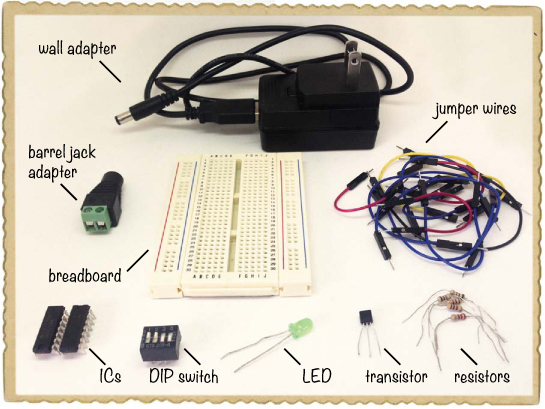
![]() A breadboard (Jameco #20601, Bitsbox #CN329) with at least 30 rows.
A breadboard (Jameco #20601, Bitsbox #CN329) with at least 30 rows.
![]() Breadboard jumper wires (Jameco #2237044, Bitsbox #CN236)—you’ll need around 20 for this project.
Breadboard jumper wires (Jameco #2237044, Bitsbox #CN236)—you’ll need around 20 for this project.
![]() A DIP switch (Jameco #38820, Bitsbox #SW042) with four individual switches.
A DIP switch (Jameco #38820, Bitsbox #SW042) with four individual switches.
![]() A 74LS04 inverter IC with six NOT gates (Jameco #46316, Bitsbox #QU108)
A 74LS04 inverter IC with six NOT gates (Jameco #46316, Bitsbox #QU108)
![]() A 74LS08 IC with four AND gates (Jameco #46375, Bitsbox #QU109)
A 74LS08 IC with four AND gates (Jameco #46375, Bitsbox #QU109)
![]() A general-purpose NPN transistor (Jameco #254801, Bitsbox #QD011), such as BC547.
A general-purpose NPN transistor (Jameco #254801, Bitsbox #QD011), such as BC547.
![]() A standard LED (Jameco #34761, Bitsbox #OP003)
A standard LED (Jameco #34761, Bitsbox #OP003)
![]() A 220 Ω resistor (Jameco #690700, Bitsbox #CR25220R) to limit the current to the LED.
A 220 Ω resistor (Jameco #690700, Bitsbox #CR25220R) to limit the current to the LED.
![]() Four 1 kΩ resistors (Jameco #690865, Bitsbox #CR251K) to use as pull-down resistors.
Four 1 kΩ resistors (Jameco #690865, Bitsbox #CR251K) to use as pull-down resistors.
![]() A 5 V DC wall adapter (Jameco #2126125, Bitsbox #TF010) to power the circuit.
A 5 V DC wall adapter (Jameco #2126125, Bitsbox #TF010) to power the circuit.
![]() A DC barrel jack adapter (Jameco #2227209, Bitsbox #CN424) to connect the wall adapter to the breadboard.
A DC barrel jack adapter (Jameco #2227209, Bitsbox #CN424) to connect the wall adapter to the breadboard.
Tools

![]() A screwdriver that fits the screw terminal of the barrel jack adapter.
A screwdriver that fits the screw terminal of the barrel jack adapter.
How to Use Other Voltages with a Breadboard
You’ve used 9 V batteries for each circuit in this book so far, but most digital circuits need to use lower voltages. For example, a lot of ICs with logic gates inside use 5 V instead. But 5 V is not a standard battery value; there are 4.5 V and 6 V batteries, but not 5 V.
What can you do when your circuit requires 5 V? Say hello to the wall adapter and the barrel jack adapter.

Many electronic devices use wall adapters to recharge batteries or just to stay powered. The pronged side of a wall adapter plugs into a wall socket, and the other side plugs into something you want to power. Wall adapters come in many values, and this project uses a 5 V DC regulated adapter.
To supply power to a circuit, the wall adapter in this project needs to plug into a barrel jack adapter. The barrel jack adapter listed in this project’s Shopping List (page 224) has two screw terminals, where you can plug in jumper wires that connect to the breadboard. You can connect any wall adapter with the standard round plug into this barrel jack adapter.
If a circuit needs an input voltage and you don’t connect the input to anything, then that input is floating. A floating input is unreliable because the circuit may see it as a 1 or a 0, and you can’t control which.
The individual switches on a DIP switch are either open or closed. When the switch is open, the input it controls will be floating if it’s not connected to anything else. To fix this, you can attach a pull-down resistor to each input on the logic gates, like this:
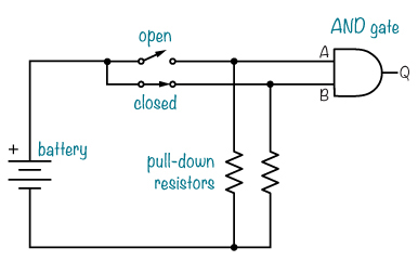
Each pull-down resistor in this circuit diagram connects to a switch and a gate input on one side and to the negative battery terminal on the other. When a switch is open, the resistor “pulls” the gate input down to 0 V, which is a 0. When a switch is closed, the gate input connects to the positive terminal and gets the positive supply voltage, which is a 1.
In this project’s circuit diagram on page 224, there are four switches with 1 kΩ pull-down resistors. All of them are shown as open, and all of the AND gate inputs would be 0 in that state.
Step 1: Place the Switches and Resistors
Plug your DIP switch in at the top of the breadboard, with one side of the switch on each side of the notch in the middle. Use jumper wires to connect the left side of each DIP switch to the positive supply rail on the left, and connect a 1 kΩ resistor from the right side of each DIP switch to the negative supply rail on the right.

Step 2: Place the ICs
Place the IC with NOT gates, marked 74LS04, in the middle of the breadboard and place the IC with AND gates, marked 74LS08, farther down. For both ICs, point the rounded notch toward the DIP switch. Leave at least three rows at the bottom of the breadboard for the transistor.

Step 3: Place the Transistor and LED
Plug your transistor into three rows at the bottom of the breadboard. If you used the BC547 transistor from this project’s Shopping List (page 224), face the flat side left so that the collector is the upper pin, the base is the middle pin, and the emitter is the bottom pin. If you used a different NPN transistor, check its datasheet to see which pin is which.
Connect the LED’s short leg, the cathode, to the same row as the collector. Connect the LED’s long leg, the anode, to an empty row on the left side of the breadboard. Finally, connect the 220 Ω resistor from the LED’s anode to the positive supply rail.

Step 4: Build the Logic Circuit
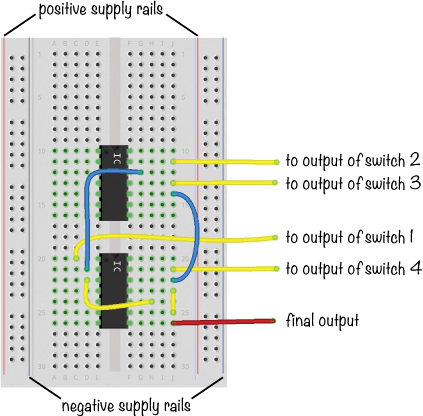
First, look at the following diagram to see where the AND and NOT gates are inside your ICs and to see the connections you need to make.

Take four jumper wires and connect them from the switch outputs to the gate inputs as follows:
![]() The output from switch 1, the uppermost switch, goes to the AND gate input on pin 1 of the lower IC (74LS08).
The output from switch 1, the uppermost switch, goes to the AND gate input on pin 1 of the lower IC (74LS08).
![]() The switch 2 output goes to the NOT gate input on pin 13 on the upper IC (74LS04).
The switch 2 output goes to the NOT gate input on pin 13 on the upper IC (74LS04).
![]() The switch 3 output goes to the NOT gate input on pin 11 on the upper IC.
The switch 3 output goes to the NOT gate input on pin 11 on the upper IC.
![]() The switch 4 output goes to the AND gate input on pin 13 of the lower IC.
The switch 4 output goes to the AND gate input on pin 13 of the lower IC.

Next, get two jumper wires to connect the outputs of the NOT gates to the AND gate inputs like this:
![]() One jumper wire goes from pin 12 on the upper IC to pin 2 on the lower IC.
One jumper wire goes from pin 12 on the upper IC to pin 2 on the lower IC.
![]() The other jumper wire goes from pin 10 on the upper IC to pin 12 on the lower IC.
The other jumper wire goes from pin 10 on the upper IC to pin 12 on the lower IC.
Now, each output from the AND gates needs to go into the third AND gate, as follows:
![]() Connect one jumper wire from pin 3 to pin 10 of the lower IC.
Connect one jumper wire from pin 3 to pin 10 of the lower IC.
![]() Connect another jumper wire from pin 11 to pin 9 on the lower IC.
Connect another jumper wire from pin 11 to pin 9 on the lower IC.
![]() Finally, connect a jumper wire from the final output of the AND gate with the other side hanging loose for now.
Finally, connect a jumper wire from the final output of the AND gate with the other side hanging loose for now.
Your IC connections should look like this:
Step 5: Finish Wiring the Transistor
Now, connect the output from the final AND gate—pin 8 of the lower IC—to the base of the transistor. This output will control whether the transistor allows current to pass through to the LED or not. Connect a jumper wire from the emitter of the transistor to the negative supply rail.

Step 6: Power and Test the Secret Code Checker
Connect jumper wires from pin 14 on both ICs to the positive supply rail and from pin 7 of both chips to the negative supply rail. Then, turn off all the switches on the DIP switch and connect your 5 V source, with plus to the positive supply on the left and minus to the negative supply on the right.
Use your barrel jack adapter with a couple of jumper wires to make this connection. The barrel jack adapter should have + and – markings to tell you which supply is which. Just loosen the screws on the adapter, insert a wire into each, and tighten the screws again. Follow the conventional color code by using a red wire for positive and a black wire for negative so you will be sure to connect them the correct way on your breadboard.
The LED should stay dark when the switches are off, but when you set the code to 1001 by switching on the top and bottom switches, it should light up.

Step 7: What If the LED Doesn’t Light Up?
First, check that the two ICs have power. Do both ICs have pin 14 connected to the positive supply column and pin 7 connected to the negative supply column? If you find the ICs become too hot to touch, disconnect the 5 V power supply from the wall immediately and wait for the ICs to cool down. Then, make certain you have the supply connections the correct way before trying again. The wire plugged into the barrel jack adapter’s positive (+) terminal should be plugged into the positive supply column on the breadboard, and the wire in the barrel jack adapter’s negative (–) terminal should be plugged into the negative supply column.
If the ICs are powered and the circuit still doesn’t work, then check the input values on the switches. Use a multimeter to measure the voltage from the negative supply rail to the pins on the AND and NOT gates that take inputs from the switches. You should get 5 V on pins 1 and 13 of the AND IC and 0 V on pins 11 and 13 of the NOT IC. Check that the output from each AND gate you’re using is 5 V, too; you should see 5 V on pins 3, 8, and 11. If any AND gate in the IC doesn’t output 5 V, then one of its inputs is 0 V. Figure out why it’s 0 V, and you should find the problem.
Instead of an LED and a resistor, you can connect a relay to the Secret Code Checker and combine this project with the intruder alarm you built in Chapter 1. Connect the 9 V battery to the intruder alarm through the relay so that when you input the right code, the power to the alarm is cut and the noise stops. Refer back to “Meet the Relay” on page 97 to see how to connect a relay.
Notice that the secret code checker, with its 5 V supply, is being used to control the completely separate intruder alarm circuit with a 9 V supply. Connecting two circuits with separate power supplies this way is okay because there’s no electrical connection between the two circuits. Relays are useful when you need to control a circuit with a different type of power supply!
Here’s the circuit:

And these are the components you’ll need:
![]() The circuit from “Project #2: Intruder Alarm” on page 11
The circuit from “Project #2: Intruder Alarm” on page 11
![]() The circuit from “Project #21: A Secret Code Checker” on page 223
The circuit from “Project #21: A Secret Code Checker” on page 223
![]() A 5 V relay (Jameco #842996, Bitsbox #SW073)
A 5 V relay (Jameco #842996, Bitsbox #SW073)
NEGATIVE LOGIC GATES
AND, OR, and NOT are basic logic gates, and you can combine them to create new ones. Let’s look at two more gates that are created this way.
NAND Looks for One False Input
The NAND gate works like an AND gate with a NOT gate inverter on the output. The little circle on the output means NOT. That means the output from the NAND gate is 0 when both A and B are 1.

NOR Looks for Two False Inputs
The NOR gate works like an OR gate with an inverter on the output. The output is 1 when both A and B are 0.

In this chapter, you learned how to use logic gates to build circuits that “decide” things, like whether a code is correct or not. And at the end, you got to see some negative logic gates as well. Understanding how negative logic gates work is helpful, because they are often used in real-life circuits. In fact, you’ll use them in Chapter 11.
If you want to explore gates a bit further, I suggest you try combining some logic gates you’ve learned about on paper to create an XOR gate. An XOR gate gives out 1 only if the inputs are different from each other.

By combining logic gates in different ways, you can create almost anything you can imagine. But that might be a bit hard to see right now, so in the next chapter, I’m going to show you some more building blocks you can create with logic gates. You’ll learn how to build your own memory circuit, and then you’ll build your own electronic coin tosser!