▶ 11.4 Internet Addresses in Practice
Like telephone numbers, there are physical constraints on how we assign numerical IP addresses. Every address contains two parts: the “network bits” and the “host bits” in the address. The upper bits in the address form the network address. The lower bits form the host address.
The distinction between network and host bits is essential for routing packets on the internet. Routing tables describe how to locate networks, not hosts. Once the packet arrives on its destination LAN, we can use ARP to find the right host. The challenge is to reach the network from elsewhere on the internet.
When a router receives a packet, it extracts the packet’s destination IP address, then it sets the host bits to zero, leaving only the network bits. The router searches its routing table using only the network bits of the IP address. To do this, the router must know the dividing line between the network address and the host address.
Network Masks
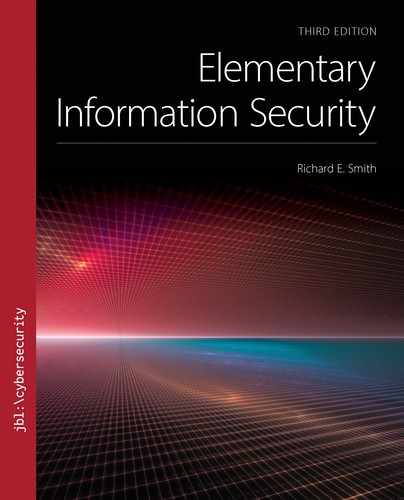
As the internet address space was depleted in the 1990s, the address format was revised to introduce a network mask: a binary value containing a row of 1 bits to identify the network address bits. FIGURE 11.11 illustrates a network mask.
FIGURE 11.11 Interpreting a network mask.
In Figure 11.11, the first 20 bits of the mask are set to 1. This indicates that the network address consists of the first 20 bits. The remaining 12 bits select a specific host on that network.
When an organization wants to put a lot of hosts on the internet, it signs up for a series of IP addresses to assign its hosts. If it needs 500 addresses, then it needs log2(500) bits, rounded upward, to identify those different hosts. That requires 9 bits. In an IPv4 address, that leaves 21 bits for the network address.
IPv4 Address Classes
Originally, the dividing line between host and network address was always on a byte boundary. This produced three “classes” of IP addresses:
Class A. There were 128 of these; each supporting over 16 million hosts on the network.
Class B. There were over 16,000 of these; each supporting over 65,000 hosts on the network.
Class C. There were over 2 million of these; each supporting 254 hosts on the network.
Class A network addresses were assigned to large or significant organizations involved in internet development. Even today, many of those addresses still belong to the original organizations.
In practice, the address class arrangement breaks the address space into inconvenient fragments. Network sites would be assigned Class B addresses to support less than 1000 computers, reducing the number of network addresses available to other sites. The network mask allows ISPs to assign smaller blocks of addresses to individual organizations.
11.4.1 Addresses, Scope, and Reachability
In computer science, we use the term “scope” to talk about the range over which something has meaning; a variable’s scope inside a program, for example, depends on where and how we define it. When we apply scope to addresses, we indicate the part of the network over which we can use the address to deliver a packet. Address scope is based on the protocol layer at which the address is defined. TABLE 11.1 summarizes the different types of addresses and their corresponding network scopes.
TABLE 11.1 Scope of Addressing Information in Internet Packets |
||
|---|---|---|
| Layer | Address Type | Scope |
| 2 | MAC address | Can reach across all interconnected Layer 2 devices |
| 3 | IP address | Can traverse Layer 2 devices and Layer 3 routers that contain routes for the destination address |
| 4 | Port number | Limited to the transport layers on the endpoints |
FIGURE 11.12 illustrates a simple network of Layer 2 and Layer 3 nodes. As in the Ethernet, Layer 2 nodes are hubs and switches. In internet protocols, Layer 3 nodes are routers.

FIGURE 11.12 Reachability depends on address scope.
If we have a Layer 2 address, we can reach any device connected to our host via a Layer 2 path. If we have a Layer 3 address, we can reach any host at Layer 2 by using an ARP request to retrieve the MAC address. We also can reach hosts on the other side of a Layer 3 router if the router has a route to that host. This is likely on small networks, like the one shown in Figure 11.12.
When we look at Figure 11.12 in terms of address scope, we find that some hosts can’t reach other hosts, depending on the type of address being used. If the hosts only have transport addresses (port numbers, for example), then they don’t have enough information to reach another host, even if that host is the only one offering a service on that port. If all hosts have shared Layer 3 addresses (IP addresses) with each other, then all hosts can reach one another.
If we limit the hosts to Layer 2 addresses, however, we run into limitations. A MAC address can’t reach another host on the other side of a Layer 3 router, like the one in the upper-left corner of the figure. We can illustrate which hosts can reach which with the “reachability matrix” as shown in TABLE 11.2. There is a check mark if the source host in the left column can reach the given destination host.
TABLE 11.2 Layer 2 Reachability Matrix for Figure 11.12 |
|---|

|
11.4.2 Private IP Addresses
Because IPv4 addresses are only 32 bits long, there are approximately 4 billion of them. The global internet assumes that all such addresses are unique, otherwise, the routers could not decide which host should receive packets with a duplicated address. Unfortunately, the internet has run out of these global IP addresses. These global addresses carry packets directly between internet hosts.
When a household or small business signs up for internet service, the ISP usually assigns the customer a single, global IP address. A larger company might request a range of addresses, but there aren’t enough addresses to assign one to each computer. Instead, many networks use private IP addresses. These addresses are valid only within the private LAN. When a host on the LAN needs to communicate with a host on the global internet, the address must be translated to a global IP address.
Most home and small business networks connect to their ISP through a low-cost commercial gateway like the one shown in FIGURE 11.13. The gateway performs three important functions:
Automatically assigns IP addresses to the LAN’s hosts using the Dynamic Host Configuration Protocol (DHCP).
Provides a router to exchange packets between the LAN and the remainder of the internet.
Performs network address translation (NAT), which allows the hosts on the LAN to share the global IP address assigned by the ISP.

FIGURE 11.13 Typical low-cost commercial gateway.
Courtesy of Dr. Richard Smith.
We examine such gateways and the NAT function further in Section 12.4.
The gateway in Figure 11.13 provides three types of physical network connections. The leftmost RJ-45 port provides an uplink that connects to the internet. The remaining four RJ-45 ports are downlinks from a built-in switch. These allow four computers, or other switches, to connect to the gateway. Finally, the antenna on the right provides a wireless hub.
Assigning Private IP Addresses
When a host on the LAN boots up or otherwise arrives on the LAN, it uses DHCP to announce its presence on the network. The gateway responds and assigns it an IP address. Instead of assigning a global IP address, the gateway assigns each host a private IP address.
Private IP addresses are assigned out of a special range of addresses dedicated for that purpose. These addresses don’t conflict with any other addresses assigned on the internet, except in other private networks. Private IP addresses fall in the following ranges:
■ 10.0.0.0–10.255.255.255: 24 bits of host address
■ 172.16.0.0–172.31.255.255: 20 bits of host address
■ 192.168.0.0–192.168.255.255: 16 bits of host address
Private IP addresses may only be used on a private network. When using private addresses, there must be a gateway between the private network and the rest of the internet. The gateway must perform NAT to convert the private addresses into recognized, public internet addresses. If a packet appears on the public internet with a private IP address, many internet routers will discard it. Typical gateways like the one in Figure 11.13 handle the translation automatically. We examine NAT in Section 12.4.1.
Dynamic Host Configuration Protocol
When a host boots up or it activates a dormant network interface, it starts by broadcasting a DHCP Query message. The broadcast packet is seen by every host on the LAN, including the gateway. The gateway’s DHCP server sees the request and chooses an IP address for the host, then it sends the host a DHCP ACK message, which gives the host its IP address and the addresses of other important services on the LAN.
When assigning private addresses, the DHCP function uses a particular range of addresses and assigns private addresses from that range. When a host opens a connection to a host on the global internet, the gateway’s NAT function converts the host’s private IP address to the gateway’s public IP address.