

Installing the VMware ESXi 5.1 using N series storage
This chapter explains how to install and configure the VMware ESXi 5.1 operating system by using local disks on a server. It includes the following topics:
5.1 Pre-installation tasks
Before having your VMWare host running, serving your virtual machines with hardware resources, it is a good idea to check the integrity of them. A good practice is to run memory tests for 48 hours before installing VMWare ESXi to ensure that the hardware is OK to enter into production.
In our scenario, we are installing ESXi 5.1 in a local disk, so the installation is straightforward. We just need to check whether the server is able to find the local disk using the local storage adapter. Then we create a logical volume as a RAID 1, also known as a mirrored drive.
If you are using the boot-from-SAN feature of VMware ESXi, before starting the installation of the operating system, you need to perform the following tasks:
•Ensure that the logical unit number (LUN) is properly created and mapped in the N series.
•Ensure that the fiber connection between the N series system and the server is done through a SAN switch.
•Verify that the LUN zoning is properly set up in the SAN switch.
•Ensure that the server’s HBA is configured to be bootable.
•Set up the correct boot sequence by using the Basic Input/Output System (BIOS) of the server.
|
Preferred practice: If for any reason the server already has data LUNs zoned, unzone them before installing the operating system to avoid data loss. Leave only the LUN for the ESXi installation zoned to the server.
|
•Download ESXi 5.1 OS installation ISO from the VMware website:
https://my.vmware.com/web/vmware/info/slug/datacenter_cloud_infrastructure/vmware_vsphere/5_1
5.2 Boot options for VMware ESXi Servers
You can choose to install the VMware ESXi Server on your local drive or in a storage LUN, also known as boot from storage area network (SAN). To help you to decide what option to use, consider the most beneficial setup for your environment, using these guidelines:
•Install the VMware ESXi by using local drives:
Choose this option if you have the following situations:
– You have storage space problems.
– You are concerned with troubleshooting if you lose SAN connectivity.
•Install the VMware ESXi by using boot from a SAN:
Choose this option if you have the following situations:
– You are concerned about local hard disk maintenance and an extra level of redundancy.
– You are installing ESXi in a diskless blade system.
– You want to be able to clone the ESXi operating system for multiple future deploys or for disaster recovery purposes.
|
Boot from SAN: VMWare supports boot from SAN by using Fibre Channel Protocol (FCP) or the iSCSI protocol. When using iSCSI, it is only supported if it is hardware initiated.
|
5.3 Preparing N series for the VMware ESXi Server
To boot from SAN and install the ESXi operating system in the server, prepare the storage system to accommodate the boot LUN. Complete the items on the following checklist before you begin:
1. Check the hardware elements, such as host bus adapters (HBAs), and storage devices. They must be compatible and configured according to the boot from SAN requirements. Note the following requirements:
– HBA. The BIOS of the HBA Fibre Channel must be enabled and configured for boot from SAN. See the HBA setup in 5.3.3, “Configuring Fibre Channel HBA for boot from SAN” on page 76.
– LUN. The bootable LUN cannot be shared between other servers. Only the ESXi Server that is actually using the LUN can use the LUN.
2. When you boot from an active/passive storage array, the Storage Processor whose worldwide port name (WWPN) is specified in the BIOS configuration of the HBA must be active. If that Storage Processor is passive, the HBA cannot support the boot process.
3. Make the fiber connection between the N series and the server through a SAN switch. Boot from SAN is not supported if the storage and the server are directly connected. The boot LUN must be properly zoned in the SAN switch.
5.3.1 Preparing N series LUNs for the ESXi boot from SAN
To set up a LUN in the N series to be used as a bootable LUN for the ESXi server:
1. Log in to the IBM N series System Manager:
a. Launch an IBM N series System Manager 2.0 console.
|
Tip: This step assumes that you have discovered and added your N series storages to the System Manager console.
|
b. Enter a user name and password, as shown in Figure 5-1.

Figure 5-1 N series Overview authentication window
The main menu bar in the left pane of the window is displayed. From there, you can control most of the features of the storage system, as shown in Figure 5-2.

Figure 5-2 Main menu window
2. Create an aggregate:

Figure 5-3 Selecting the option to create an aggregate
Figure 5-4 Aggregate Wizard Welcome window
c. In the Aggregate Parameters panel (Figure 5-5), give the aggregate a name. In this example, we call it esx_boot_aggr. Select the Double Parity check box if you want to use RAID-DP level. Click Next.
|
RAID-DP: With RAID-DP, you can continue serving data and recreate lost data even if you have two failed disks. With 64-bit block format, the 16 Tb size limitation is increased and the new maximums are defined by the storage system model.
|
Figure 5-5 Naming the aggregate

Figure 5-6 Selecting disk pool

Figure 5-7 Aggregate setup - disk selection

Figure 5-8 Committing the aggregate setup
g. After the aggregate is created, in the left pane of the System Manager window (Figure 5-9), find the aggregate by selecting Aggregate.

Figure 5-9 New aggregate
3. After the aggregate is defined, create a volume:
a. In the left pane of the System Manager panel, select Volume → Create.
b. In the create Volume panel (Figure 5-10), select the Aggregate, Volume size, and Storage Type, and click Create.

Figure 5-10 Create Volume panel
c. After the volume is created, in the left pane of the System Manager panel (Figure 5-11), select Volumes to view the volume.

Figure 5-11 New volume
4. After you create the volume, add the LUN that is to be used by the VMware ESXi Server as a bootable LUN:
a. In the left pane of the System Manager console, select LUNs → Create.
b. Click Next on the Welcome panel.
c. In the Create LUN Wizard (Figure 5-12), type the new LUN Name, select the Protocol Type and type the LUN Size. Then click Next.

Figure 5-12 Setting up the LUN
d. In the LUN Container panel, browse or type the Volume path created previously (Figure 5-13) and click Next.

Figure 5-13 Select LUN path
e. In the next panel add an Initiator Group to map the LUN. Click Add Initiator Group (Figure 5-14).

Figure 5-14 Add Initiator Group
f. In the Create Initiator Group panel, type the new Initiator Group Name, select the Operating System and Protocol Type as shown in Figure 5-15.

Figure 5-15 Create initiator panel
g. Still on the Create Initiator Group panel, click the Initiators tab, then click Add.
In this panel, type the WWPNs or the iSCSI information for the server adapter (Figure 5-16) based on which protocol you selected on the previous step.
Click OK and Create.
In this panel, type the WWPNs or the iSCSI information for the server adapter (Figure 5-16) based on which protocol you selected on the previous step.
Click OK and Create.

Figure 5-16 Initiator adapter information
h. Back to the Initiator Mapping panel, select the initiator created and type a LUN ID (Figure 5-17) and click Next.

Figure 5-17 Initiator mapping panel
|
Tip: Type a LUN ID is not mandatory, but helps to identify the LUNs when you have many mapped to a specific server.
|
i. Click Next on the Summary Review panel to create the LUN, then click Finish.
j. To see the new LUN, in the left pane of the System Manager panel (Figure 5-18), select LUNs. You will be able to see that the mapping is already done also.

Figure 5-18 New LUN without mapping
5.3.2 Zoning a LUN in the SAN switch
Because the connection of a bootable LUN for the VMware ESXi operation system must go through a SAN switch, you must properly zone the bootable LUN to the server’s HBA:
1. Launch an Internet browser and type the following URL:
http://<SAN_switch_address>
Where SAN_Switch_address is the name or IP address of your SAN switch system.
2. In the main window, click the Zone menu icon at the bottom of the window (circled in Figure 5-19).

Figure 5-19 Clicking the Zone menu icon
3. When prompted, enter your user name and password to access the zoning feature of the SAN switch, as shown in Figure 5-20. Then click OK.

Figure 5-20 Signing on to access the zoning feature of the SAN switch
4. In the LUN zoning window (Figure 5-21), on the Zone tab, click the Create button to add a new zone.

Figure 5-21 Creating a new zone
a. In the Create New Zone window (Figure 5-22), give the new zone a name. In this example, we name it boot_server1. Then click OK.

Figure 5-22 Naming the new zone
b. Assign the proper WWPNs of the storage system and the server’s HBA to the new zone (Figure 5-23):
i. From the Name list, select the proper zone name.
ii. Expand the WWPN menu to see your storage and server’s WWPNs, and select each of them.
iii. Click the Add Members button.

Figure 5-23 Assigning the WWPNs of the storage system and server HBA to the zone
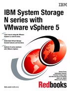
5. Click the Config tab (Figure 5-24) and add the zone named boot_server1 to the switch configuration. This example has a switch configuration named VMware. Click the proper zone name and then click the Add Members button.
Figure 5-24 Adding members to the switch configuration
6. To deliver the LUN to the server and make it available, complete these steps:
a. Select Actions → Enable Config to enable the SAN switch configuration with the new zone as shown in Figure 5-25.

Figure 5-25 Enabling the SAN switch configuration
b. In the Enable Config window (Figure 5-26), select the configuration to enable. In this example, we select VMware configuration. Click OK.

Figure 5-26 LUN zoning - enable configuration selection

Figure 5-27 Replacing the SAN switch configuration
Figure 5-28 shows the log section is at the bottom of the window. You can make sure that the SAN switch configuration was enabled successfully when the log message Commit Succeeded is shown. The server can now use this LUN.

Figure 5-28 LUN zoning - commit SAN zone changes
5.3.3 Configuring Fibre Channel HBA for boot from SAN
Now that you have created the LUN of the VMware operating system and zoned it to the server, you can configure the HBA device of the server as a bootable device.
|
EMULEX HBAs: This example shows how to configure a QLogic HBA as a boot device. For EMULEX HBAs, see the EMULEX documentation at the following website:
|
Configuring the QLogic HBA
To configure the QLogic HBA, follow these steps:
1. Boot the server and, during the post, press Ctrl-Q to enter the QLogic BIOS (Figure 5-29).

Figure 5-29 HBA setup - step 1
2. Select the HBA to be used (if more than one is available) and press Enter.
3. In the Fast!UTIL Options panel (Figure 5-30), use the arrows keys to highlight the Configuration Settings option and press Enter.

Figure 5-30 Selecting the Configuration Settings option

Figure 5-31 Selecting the Adapter Settings option
5. In the Adapter Settings panel (Figure 5-32), for Host Adapter BIOS, change the value to Enabled. You can also see the WWPN of the HBA in the Adapter Port Name field. Press Esc to exit this page.

Figure 5-32 Enabling Host Adapter BIOS
6. In the Configuration Settings panel as shown before (Figure 5-31), select the Selectable boot settings option and press Enter.
7. In the Selectable Boot Settings panel (Figure 5-33), highlight the Selectable Boot option and change it to Enable.
In this same panel, you can see the WWPN of your HBA; highlight it and press Enter.

Figure 5-33 Enabling Selectable Boot
8. Now that the HBA is ready to be a bootable device, press the Esc key and choose the option Reboot Server (Figure 5-34).

Figure 5-34 HBA setup
Configuring the boot sequence
If the server has internal disks, you can configure the HBA device with a higher priority in the server’s boot sequence. You enter the BIOS settings of your server and configure the boot sequence to make the CD drive the first boot device and the HBA the second boot device.
This example shows how to configure the boot sequence in BIOS Version 1.09 of an IBM System x3850 server.
|
HBA: Depending on your version of the BIOS, the HBA is referred to as Hard Disk 0 and not as the HBA itself.
|
Follow these steps:
1. During the post of the server, press F1 to go to the system BIOS.
2. In the Configuration/Setup Utility panel (Figure 5-35), use the arrow keys to highlight Start Options. Press Enter.

Figure 5-35 Selecting Start Options
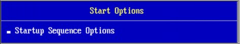
Figure 5-36 Selecting Startup Sequence Options
4. In the Startup Sequence Options panel (Figure 5-37), for First Startup Device, type CD ROM, and for Second Startup Device, type Hard Disk 0. Press Esc to return.

Figure 5-37 Specifying the first and second startup devices
Executing the Disable Bit feature
Two new requirements must be addressed on the server BIOS:
•ESXi 5.1 supports only LAHF and SAHF CPU instructions.
•ESXi 5.1 requires the NX/XD bit to be enabled for the CPU in the BIOS.
It means that the following feature also needs to be enabled as shown in Figure 5-38.

Figure 5-38 Enable Execute Disable Bit feature
To enable this feature, follow these steps:

Figure 5-39 Saving the changes and exiting the Setup Utility
2. Reboot the server.
The server and LUN are ready for the ESXi operating system installation.
5.4 Installing the ESXi operating system
To install the ESXi operating system, follow these steps:
1. Insert the ESXi operating system installation CD into the CD tray or mount the ISO image if you are using a remote card.
2. When prompted to select the installation mode, as shown in Figure 5-40, choose either the graphical (GUI) or text interface. Press Enter to choose the GUI.

Figure 5-40 Choosing the ESXi installation mode
The installer loads the necessary drivers (such as HBA and network card drivers) for the operating system installation.
3. After the media test is successfully completed and the installation wizard starts, in the Welcome window in Figure 5-41, click Next.

Figure 5-41 ESXi 5.1 Welcome window
4. In the license agreement panel, in Figure 5-42, read the license text. If you agree with the terms, press F11 to proceed with the installation.

Figure 5-42 License agreement panel
5. In the next step, shown in Figure 5-43, VMWare lists the physical disks found during its scanning. Those disks include local ones and LUNs provided to be used by the SAN boot systems panel (choose how you want to set up the initial system partition).

Figure 5-43 Selecting the disk to install ESXi 5.1
6. Because we are upgrading the ESXi from a previous installation, the next panel (Figure 5-44) shows the upgrade confirmation.

Figure 5-44 Installer waiting the confirmation to start upgrade(F11)
7. The installation takes few minutes and finishes successfully as shown in Figure 5-45.

Figure 5-45 Installation completed
8. Remove the CD or unmount the ISO, then restart the server, and you have the following panel, as shown in Figure 5-48.

Figure 5-46 Fresh installed ESXi 5.1
9. Press F2 to customize the server, then enter the root password as shown in Figure 5-47, which is empty by default, so just press Enter.

Figure 5-47 Login to the ESXi host
10. The first highlighted option is Configure Password, so press Enter to set it.
11. Type it twice on the next panel and press Enter again.
12. Then go to the Configure Management Network option, press Enter, select IP Configuration, and press Enter again.
13. Then configure the host with your networking settings, as shown in Figure 5-48.

Figure 5-48 Setting network information on the host
14. After setting the network, press Enter, go to DNS configuration, and press Enter. Type the network information and the hostname of the server, as shown in Figure 5-49.
Press Enter.
Press Enter.

Figure 5-49 Set the DNS servers and the Hostname
15. Press Esc to leave the Configure Management Network, and on the confirmation panel, select Y, as shown in Figure 5-50.

Figure 5-50 Restarting the management network to apply changes
16. Connect the host to a vCenter and apply all the available patches.
17. Take a backup of your host configuration by using vSphere CLI, running the following command:
vicfg-cfgbackup --server <ESXi-host-ip> --portnumber <port_number> --protocol <protocol_type> --username username --password <password> -s <backup-filename>
Use the -s option to point to the location where the file with the host configuration is intended to be saved.
..................Content has been hidden....................
You can't read the all page of ebook, please click here login for view all page.