
In this chapter, rather than create a new game, you will learn two techniques for incorporating sophisticated graphics into your projects. The first section will introduce particle systems, which can create special effects such as explosions, which will be incorporated into the Space Rocks game in place of the spritesheet-based animation. The second section will introduce shader programs, which manipulate the pixels of the rendered image to create effects such as blurring or glowing, which will be incorporated into the Starfish Collector game.
Particle Systems
A particle system is a collection
of many small images that can be used to create a variety of graphical special effects. Some effects that can be replicated by this technique include fire, smoke, explosions, fireworks, electric sparks, water fountains, rain, snow, and star fields. Each of the small images in a particle system is called a
particle
. Every particle has many properties (such as velocity, size, color, and transparency) that can be initialized to a random value within a given range, and these property values may be configured to change over time. Particles are produced at a set rate by an object called an
emitter
, which may be configured to spawn particles either for a limited time or continuously, depending on the visual effect being created.
LibGDX provides classes that support the display of particle systems. Furthermore, the Particle Editor tool provided with LibGDX can be used to design and preview particle effects and then to export them to a file format that can be easily imported within the LibGDX framework.
The LibGDX Particle Editor
The LibGDX Particle Editor can be run directly from the source code, as explained on the LibGDX wiki.1 However, for simplicity, you can use the executable JAR file ParticleEditor.jar
, available in the Particle Editor folder in the source code directory for this chapter. Figure 15-1 shows this program when it is first started
.
Figure 15-1.
The LibGDX Particle Editor program at startup
A fire effect appears in the preview region in the upper-left panel of the Particle Editor window. The parameters that produce this effect are shown in the Emitter Properties
panel that occupies the majority of the right-hand side of the window. This panel has so many properties, each with corresponding values and graphs, that it can be somewhat overwhelming at first. This section will discuss only the emitter properties
that have the greatest impact on the final visual effect; for more thorough coverage, please consult the LibGDX wiki (previously referenced) for details.
- Image: From this area, you can select the image to use for each particle. Particles are often tinted with a color; grayscale images work best for this purpose.
- Count: This area can be used to set the minimum and maximum number of particles that should appear onscreen at any time.
- Duration: This is how long the emitter will produce particles. (When creating a continuous effect, this value will be ignored.)
- Emission: This is how many particles will be emitted per second.
- Life: This is how long each particle will be active in the particle system.
- Size: This is the size of the image, in pixels.
- Velocity: This is the particle speed, in pixels per second.
- Angle: This is the particle direction, in degrees.
- Tint: This displays the color(s) used to tint the particle image.
- Transparency: This controls the transparency of the particles over time.
- Additive: When active, this blends colors by adding together the color components, resulting in brighter areas where many particles are present.
- Continuous: When active, this causes the emitters to continue emitting particles (ignoring the preceding Duration value).
Next to some of the parameters
, you’ll see text boxes and a graph, as shown in Figure 15-2, which can be used for fine-tuning the initial values and changes in values over time. (For some parameters, you will need to click the Active button to the right of the parameter name to make these elements appear.)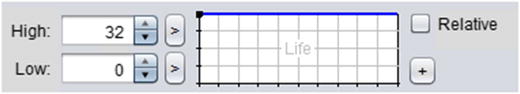
Figure 15-2.
Particle Editor interface for fine-tuning parameter values
The numeric values
in the boxes labeled High and Low refer to the values of the top and bottom edges on the graph to the right. The blue line on the graph indicates how the parameter value will change during the lifetime of the particle. In the graph pictured in Figure 15-2, the dark blue line remains straight across the top, indicating that the parameter value will remain constant at the High value. Figure 15-3
illustrates two more possible graphs; the graph on the left represents a continuous decrease from the High value to the Low value, while the graph on the right represents a parameter that remains at the High value for the majority of the lifetime of the particle and then suddenly decreases to the Low value. These two graphs will be referred to as the “Gradual Decrease” and the “Sudden Decrease” graphs later in this section.
Figure 15-3.
Variations on the parameter change graph
To modify one of these graphs, you can click anywhere to add a point, click and drag to move a point around, and double-click a point to remove it.
In addition, next to the High and Low values are small buttons labeled with > or <; these can be used to toggle between one or two values appearing in the corresponding row. When two values are displayed, they represent a range of values from which the High or Low values will be randomly selected for each particle. This can be used to great effect, as you will see later.
Finally, it is useful to understand how to set the parameters for the Tint property. If desired, the color of a particle can change over time; the progression of the color is displayed from the left to the right in the topmost rectangle. For example, Figure 15-4
represents a particle that will begin tinted red, shift to blue, and finally end tinted green. As with the parameter-change graphs discussed previously, additional points (represented by triangles) can be added by clicking within the rectangle. Triangles can be selected by clicking them, and their colors can be adjusted by using the sliders underneath, which control the hue, saturation, and brightness of the color. The triangles can be moved by clicking and dragging, and they can be deleted by double-clicking.
Figure 15-4.
The tint parameter graph
With this knowledge of the user interface
of the Particle Editor, you’ll work through examples that show how to create particle-based versions of the effects from the game Space Rocks. Creating lots of effects, more than anything, is what will ultimately give you a feel for the role each parameter plays in crafting a particle-based effect.
You need a location to save your final effects, so at this time, create a copy of your
Space Rocks project
from Chapter 4 and rename the copy to Space Rocks Particles. You will store the effect files created with the LibGDX Particle Editor in the assets folder of this directory. Also, download the source files for this chapter, and from the assets folder of the downloaded Space Rocks Particles project, copy the image file particle.png into the assets folder of your Space Rocks Particles project.
Rocket-Thruster Effect
Your first goal is to create a rocket-thruster effect, pictured in Figure 15-5.
Figure 15-5.
The rocket-thruster particle effect
After starting the Particle Editor program, in the Effect Emitters panel in the lower left, click the New button and rename the newly created list entry thruster (double-click its name to rename it). Click the list item named Untitled (which corresponds to the default fire-like example) and click the Delete button to remove it.
In the set of options at the bottom of the Emitter Properties panel, deselect the “Additive” checkbox and select the “Continuous” checkbox. You should now see a single red dot in the middle of the preview panel.
First, you will adjust the number of particles that will be active at any given moment. Change the Count property’s Max value to 100. To achieve this amount, you also must change the Emission property’s High value to 200. (Changing this value to 100 would be insufficient, as each particle lasts for only 0.5 seconds, since 500 milliseconds is the default value for the Life property. An emission rate of 100 would result in only 50 active particles at any given time.)
Next, click the Active buttons next to the Velocity and Angle properties. For Velocity, click the > button next to High and enter the values 300 and 400. For Angle, again click the > button next to High and enter the values 70 and 110. You should now see red particles spraying upward in a wobbly, cone-shaped pattern.
Now, change the Tint parameter graph so that the tint color changes from red at the start to orange in the middle and yellow at the end. After completing this step, the particles in the preview panel should appear red at the base of the emitter and gradually change colors until they become yellow at the top.
Finally, the particles should shrink and fade out of existence at the end of their lifetime. To accomplish this, modify the parameter-change graphs for both Size and Transparency so that they both resemble the Sudden Decrease graph from Figure 15-3.
When this step is finished, click the Save button and save your file to your project assets directory using the filename thruster.pfx. Although the particle-effect data
is stored in a text file, you will use the extension pfx as a mnemonic to indicate the type of data in the file. In addition, you will need to copy the image file particle.png from the Particle Editor directory to your local project’s assets directory as well, if you haven’t previously, for the effect to load correctly in LibGDX.
Explosion Effect
A classic effect that you will now create is an explosion, as illustrated in Figure 15-6. This effect is composed of two emitters, one controlling the fire that appears initially, and the other controlling the smoke that appears afterward.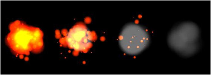
Figure 15-6.
The explosion particle effect
Restart the Particle Editor. As before, create a new emitter. Name it fire and then delete the default emitter. You’ll keep the default option settings: the “Additive” checkbox should be selected, and the “Continuous” checkbox should not be.
Adjust the Count property’s Max value to 100. Change the Duration value to 250. To attain the maximum number of particles, change the Emission property’s High value to 400. Set the Size property’s High value to range from 0 to 100, and modify the graph so that it resembles the Gradual Decrease graph. Set the Velocity property to Active, set its High value to range from 0 to 160, and modify its graph so that it resembles the Sudden Decrease graph. Set the Angle property to Active and set its High value to range from 0 to 360. Finally, set the Tint property so that the color changes from red to orange over the course of the particle lifetime.
At this point, the Preview panel should be displaying the following effect repeatedly: a globule shape appears, red at the borders and yellow in the center, which then expels fragments that shrink as they move away from the center.
Once you are pleased with this effect, create another emitter and name it smoke. (Do not delete the fire emitter!) Select the smoke emitter from the list and click the Up button; this moves it higher up in the rendering order. Make sure that the checkbox next to the emitter is checked for it to be seen. This is important because you want the smoke particles to appear behind the fire particles, and so the smoke particles must be rendered first. Before continuing, make sure that in the emitter list, the smoke emitter is both checked (so it is visible) and highlighted (so that the parameters that will be changed are those of the smoke emitter).
The next step is to change the smoke emitter properties. Set the Count Max value to 20, the Duration value to 200, and the Emission High value to 100. Set the Delay property to Active and set its value to 400; this will cause the smoke emitter to begin 400 milliseconds after the fire emitter has started. Next, change the Size High value to 64. Activate the Velocity property, set the High value to 100, and modify the graph so that it is gradually decreasing. Also, activate the Angle property and set the High value to range from 0 to 360. Change the Tint color to a medium shade of gray by dragging the knob on the lower-left color slider all the way to the right and then dragging the knob on the lower-right color slider to the middle. Modify the Transparency graph so that it is slowly decreasing. Last of all, uncheck the “Additive” option.
This completes the explosion effect! Save your file to the assets directory with the filename explosion.pfx.
The ParticleActor Class
At this point, you are ready to integrate particle effects into the Space Rocks game. You will first create an extension of the Actor class, called ParticleActor. This class stores a ParticleEffect object, which is used to update and draw the effect. Most of the methods in this class simply activate the methods of the corresponding ParticleEffect object, with somewhat more intuitive names. However, one feature missing from the ParticleEffect class is that its draw method is not designed to take into account rotation or scaling factors. To address this situation, you will create an inner class called ParticleRenderer that renders the particle effect, make the ParticleActor class extend the Group class instead of the Actor class, and add an instance of the ParticleRenderer to the ParticleActor. In this way, calling the ParticleActor draw method will apply the geometric transformation data to the attached object before it is drawn, which is the desired outcome.
The update and draw methods of the ParticleEffect class will be activated by the standard act and draw methods common to all Actor objects, and a clone method will be included for convenience. Open BlueJ, then open the Space Rocks Particles project you created earlier. The code for the ParticleActor class is as follows:
import com.badlogic.gdx.Gdx;
import com.badlogic.gdx.scenes.scene2d.Actor;
import com.badlogic.gdx.scenes.scene2d.Group;
import com.badlogic.gdx.graphics.g2d.Batch;
import com.badlogic.gdx.graphics.g2d.ParticleEffect;
import com.badlogic.gdx.graphics.g2d.ParticleEmitter;
public class ParticleActor extends Group
{
private ParticleEffect effect;
private ParticleRenderer renderingActor;
private class ParticleRenderer extends Actor
{
private ParticleEffect effect;
ParticleRenderer(ParticleEffect e)
{ effect = e; }
public void draw(Batch batch, float parentAlpha)
{ effect.draw(batch); }
}
public ParticleActor(String pfxFile, String imageDirectory)
{
super();
effect = new ParticleEffect();
effect.load(Gdx.files.internal(pfxFile), Gdx.files.internal(imageDirectory));
renderingActor = new ParticleRenderer(effect);
this.addActor( renderingActor );
}
public void start()
{ effect.start(); }
// pauses continuous emitters
public void stop()
{ effect.allowCompletion(); }
public boolean isRunning()
{ return !effect.isComplete(); }
public void centerAtActor(Actor other)
{
setPosition( other.getX() + other.getWidth()/2 , other.getY() + other.getHeight()/2 );
}
public void act(float dt)
{
super.act( dt );
effect.update( dt );
if ( effect.isComplete() && !effect.getEmitters().first().isContinuous() )
{
effect.dispose();
this.remove();
}
}
public void draw(Batch batch, float parentAlpha)
{
super.draw( batch, parentAlpha );
}
}
With this class ready for action, you can use it, together with the particle effects you recently generated, in the Space Rocks game.
Integrating Particle Effects into Gameplay
The next step is to replace the explosion effects and the thruster fire with the corresponding particle effects, as seen in Figure 15-7.
Figure 15-7.
The Space Rocks game with particle effects added
To begin, you will extend the ParticleActor class to create these effects. Create a new class called ExplosionEffect with the following code:
public class ExplosionEffect extends ParticleActor
{
public ExplosionEffect()
{
super("assets/explosion.pfx", "assets/");
}
}
There are three times when explosion effects should be created: when a laser collides with a rock, when a rock collides with the shields, and when a rock collides
with the spaceship. First, in the update method of the LevelScreen class, locate the block of code where the spaceship is removed from the game and replace these two lines of code
Explosion boom = new Explosion(0,0, mainStage);
boom.centerAtActor(spaceship);
with the following:
ExplosionEffect boom = new ExplosionEffect();
boom.centerAtActor( spaceship );
boom.start();
mainStage.addActor(boom);
Next, locate the two blocks of code where a rock is removed from the game (when colliding with the shields or with a laser) and, in both cases, replace these two lines of code
Explosion boom = new Explosion(0,0, mainStage);
boom.centerAtActor(rockActor);
with the following:
ExplosionEffect boom = new ExplosionEffect();
boom.centerAtActor( rockActor );
boom.start();
mainStage.addActor(boom);
To integrate the thruster effect, create a new class called ThrusterEffect with the following code:
public class ThrusterEffect extends ParticleActor
{
public ThrusterEffect()
{
super("assets/thruster.pfx", "assets/");
}
}
Then, in the Spaceship class
, remove all code containing a reference to the thrusters object: the class variable declaration, the code in the constructor used to initialize it, and the two lines of code in the act method that set the visibility of the thrusters. Then, add the following variable declaration:
private ThrusterEffect thrusterEffect;
In the constructor method, add the following code to set up and correctly position the effect:
thrusterEffect = new ThrusterEffect();
thrusterEffect.setPosition(0,32);
thrusterEffect.setRotation(90);
thrusterEffect.setScale(0.25f);
addActor(thrusterEffect);
Finally, in the act method, change the if-else statement that checks if the up arrow key is pressed to the following:
if (Gdx.input.isKeyPressed(Keys.UP))
{
accelerateAtAngle( getRotation() );
thrusterEffect.start();
}
else
{
thrusterEffect.stop();
}
With this addition
, the modifications to the Space Rocks game are complete. Test out your project; the gameplay should be the same as before, with improved special effects! In the next section, you will learn another technique for creating different types of special effects and try them out in the Starfish Collector game.
Shader Programming
In this section, you will learn about shaders: programs designed to run on a graphics processing unit (GPU)
that can be used to create sophisticated visual effects. Similar to the central processing unit in a computer, a GPU is specialized circuitry designed for accelerated image processing and rendering. All modern video games and multimedia software use shaders to leverage the power of the GPU, which uses a parallel architecture with thousands of cores running tasks simultaneously. LibGDX (more specifically, the SpriteBatch class) creates and uses shader programs in the background to render graphics efficiently. Shader programs use OpenGL (Open Graphics Library)
, a cross-platform application-programming interface for drawing 2D and 3D graphics that uses a syntax similar to the C programming language.
Rendering graphics
involves processing lots of data, which is grouped into a data structure called a vertex. Informally, you can think of a vertex as a point in space with some associated information. A vertex stores the coordinates of its position and additional data as needed, such as an associated color or
texture coordinates
, which are used to determine a corresponding location on an image. When rendering an object (such as a square that displays an image), the vertex data is sent to buffers on the GPU for high-speed access, which is processed through the following set of stages, known as the
graphics pipeline:
2
- Vertex Processing : runs a program called the vertex shader, which can perform geometric transformations (translation, rotation, and scaling) on each vertex (typically using matrix multiplication) and sends any needed data along the pipeline.
- Rasterizing: groups vertices into sets (such as triangles) and converts the corresponding area into fragment s, data structures that correspond to pixels on the display. Each fragment interpolates and stores data from the vertex shader. For example, the color stored in a fragment that corresponds to the point in the exact center of a triangle will be the average of the colors stored in the three vertices of the triangle. All the fragments are sent to the next stage of the pipeline.
- Fragment Processing: runs a program called the fragment shader to determine the color of the associated pixel that will be displayed. This can take into account associated colors, textures, and transparency. Image filters and effects can be created here, such as color tinting, blurring, or glowing effects.
After these stages are complete, the final image data is available for the display. In the sections that follow, you will learn about the default shader programs provided by LibGDX, and how to create your own fragment shaders and incorporate them in the Starfish Collector game. In particular, you will create a grayscale filter, a colored border around an image, blurred images, a glowing effect, and an animated wave-like distortion.
Default Shaders
Before diving into the actual code of the default vertex and fragment shaders used by LibGDX, a brief overview of the relevant syntax and language will be provided. This is in no way meant to be a comprehensive introduction; such an undertaking is worthy of an entire book in its own right!
Many of the variable types available in OpenGL
have similar counterparts in Java:
- float, int, and bool refer to floating-point numbers, integers, and Boolean values (one-bit integers), respectively.
- vec2, vec3, and vec4 refer to vectors with two, three, and four components. These are usually used to store position coordinates, although vec4 is also used to store color values (red, green, blue, and alpha/transparency). In addition, the arithmetic operators (+, -, *, /) can all be used on instances of these types.
- mat4 refers to a 4-by-4 matrix, which typically encodes geometric transformations (which are automatically generated for you by the LibGDX libraries).
- sampler2D refers to a two-dimensional grid of values, usually the color data associated with an image.
Many of the keywords and commands
are also used in OpenGL, such as if-else statements, for and while loops, and logical operators (&& for “and,” || for “or,” ! for “not”). There are also many mathematical functions
available, such as sqrt, pow, sin, cos, abs, round, floor, max, and min, each of which corresponds directly to a function in the Java Math class. One special OpenGL function that you will see repeatedly is called texture2D, which takes a sampler2D and a vec2 as input and returns the data from the sample (the color from the image) at the position specified by the vector; if the vector does not correspond to an exact pixel from the image, then the color will be interpolated from the colors of nearby pixels.
Both the vertex shader
and the fragment shader
must contain a single function called main with a void return type. (You can write additional “helper” functions with non-void return values if you wish, but that topic will not be covered here.) The vertex shader must assign a vec4 value to the variable gl_Position, which represents the final position of the vertex. The fragment shader must assign a vec4 value to the variable gl_FragColor, which represents the final color of the associated pixel.
You will also see variables declared externally to the main function that, in addition to having a specific data type, have one of three additional qualifiers specified:
- attribute: refers to a property of an individual vertex and may only appear in a vertex shader program. For example, the position of a vertex must be qualified as an attribute, since this data will be different for each vertex.
- varying: used for data that is sent from the vertex shader to the fragment shader. Any varying variable declaration in the vertex shader should also appear in the associated fragment shader. Values must be assigned to these variables in the vertex shader, and these variables are read-only (may not be modified) in the fragment shader. The fragment shader will interpolate the values of these variables from the values assigned to the vertices.
- uniform: refers to global values that are the same for each vertex of an object. For example, the texture data associated with an object should be qualified as uniform, since this data is the same for all vertices of an object. Similarly, geometric-transformation matrices are uniform variables, as all vertices in an object will be translated, rotated, or scaled in the same way or by the same amounts. Uniform variables can appear in either the vertex shader or the fragment shader, as necessary.
With this background, you are ready to examine the default shaders provided by LibGDX. First is the code for the default vertex shader. In this code, three attribute vectors are set up to access the position, color, and texture coordinates
of each vertex. A uniform matrix stores the geometric transformation data, as this is the same for all vertices. Two varying variables are created to forward particular data (the color and texture coordinates) along to the fragment shader, where it will be needed to determine pixel colors. Note the variable naming convention used by LibGDX: attribute variables
are prefaced by a_, uniform variables by u_, and varying variables by v_. (This convention will be used throughout the chapter.) Finally, note that the main function assigns values to the varying variables
and calculates gl_Position by multiplying the transformation matrix
by the original position of the vertex.
attribute vec4 a_position;
attribute vec4 a_color;
attribute vec2 a_texCoord0;
uniform mat4 u_projTrans;
varying vec4 v_color;
varying vec2 v_texCoords;
void main()
{
v_color = a_color;
v_texCoords = a_texCoord0;
gl_Position = u_projTrans * a_position;
}
Next is the code for the default fragment shader. In this code, there are two varying variables
, which correspond to the varying variables in the vertex shader. There is also a uniform variable that stores the texture data. In the main function, the texture2D function
(described earlier) is used to obtain color data from the associated texture. This is multiplied by the color passed from the vertex shader, which has the effect of tinting the image by whatever color was assigned to the actor via the setColor method. (The default color associated with an actor is white, and since the red, green, and blue components of white are all equal to 1.0, multiplying by this color results in no change to the original image.) The result is assigned to the gl_FragColor variable, which will be the final color of the associated pixel.
varying vec4 v_color;
varying vec2 v_texCoords;
uniform sampler2D u_texture;
void main()
{
gl_FragColor = v_color * texture2D(u_texture, v_texCoords);
}
Now that you know what the default shader programs are, you will see how to incorporate them into your game projects.
Using Shaders in LibGDX
In this section, you will learn how to add shaders to the actors in the Starfish Collector game. To begin, make a copy of the Starfish Collector project from Chapter 5 and rename the copy to Starfish Collector Shaders. In the assets folder of this project, make a new folder named shaders; this is where you will add text files containing the code for vertex and fragment shader programs. Using a text-editor program of your choice, create a new text file containing the code from the default vertex shader previously presented; save the file in the shaders folder with the filename default.vs (the extension vs is a mnemonic for vertex shader). Similarly, create a text file with the default fragment shader code and save it to the shaders folder with the filename default.fs (fs for fragment shader). In what follows, you will read the contents of these files into a String in the process of creating shader programs.
Open the Starfish Collector Shaders project. To begin, in the Turtle class, add the following import statements:
import com.badlogic.gdx.Gdx;
import com.badlogic.gdx.graphics.glutils.ShaderProgram;
import com.badlogic.gdx.graphics.g2d.Batch;
Then, add the following variable declarations to the same class:
String vertexShaderCode;
String fragmentShaderCode;
ShaderProgram shaderProgram;
To initialize the shader program, you need the code for both a vertex shader and a fragment shader. This can be obtained via the FileHandle class readString method, which returns the entire contents of a text file as a single String. With this code, you can initialize the ShaderProgram object, which automatically sends the code to the GPU and compiles it. You also need to check manually for errors after compiling the shader programs. To accomplish these tasks, add the following code to the Turtle class constructor method:
vertexShaderCode = Gdx.files.internal("assets/shaders/default.vs").readString();
fragmentShaderCode = Gdx.files.internal("assets/shaders/default.fs").readString();
shaderProgram = new ShaderProgram(vertexShaderCode, fragmentShaderCode);
if (!shaderProgram.isCompiled())
System.out.println( "Shader compile error: " + shaderProgram.getLog() );
Finally, to actually render the turtle using your custom ShaderProgram object rather than the default, you need to override the draw method from the BaseActor class and set the shader using the Batch class setShader method. When you are finished rendering the turtle, passing null as an argument to the setShader method causes the Batch class to return to using the built-in default shader provided by LibGDX. Add the following method to the Turtle class:
public void draw(Batch batch, float parentAlpha)
{
batch.setShader(shaderProgram);
super.draw( batch, parentAlpha );
batch.setShader(null);
}
At this point
, you can test your program. It should appear exactly as it did before you added the shader, which is to be expected, since all you did was reconstruct the default shaders. However, the framework you have set up will be quite useful, as you will be able to rapidly test out a series of shaders you will write in the following sections.
Grayscale Shader
Here, you will write a fragment shader that renders a texture in grayscale. When the red, green, and blue components of a color are all equal, the resulting color is a shade of gray. Therefore, to convert a color to gray, you can calculate the average of its red, green, and blue values and set all the components of the new color equal to this average. The alpha value should remain unchanged, however. The red, green, blue, and alpha values of a color c (stored as a vec4) can be accessed via c.r, c.g, c.b, and c.a, respectively. In a text-editor program, create a file named grayscale.fs (in the shaders directory, as before) with the following code:
varying vec4 v_color;
varying vec2 v_texCoords;
uniform sampler2D u_texture;
void main()
{
vec4 color = texture2D(u_texture, v_texCoords);
float average = (color.r + color.g + color.b) / 3.0;
gl_FragColor = vec4(average, average, average, color.a);
}
In your BlueJ project, in the Turtle class, locate the line of code
in the constructor method that sets fragmentShaderCode and change it to the following:
fragmentShaderCode = Gdx.files.internal("assets/shaders/grayscale.fs").readString();
That’s all there is to it; run your project, and the turtle should be displayed in grayscale!
Custom Uniform Values
Next, you will write a shader that causes a change in the appearance of an image over time. In particular, your next fragment shader will cause the turtle to smoothly change between rendering in its original color and in grayscale. To do this requires the use of a value that oscillates over time. To this end, you will create a fragment shader that contains a new uniform variable, called u_time. The Turtle class will contain a corresponding variable called time, updated in its act method, and the value of time will be sent to the shader and stored in the variable u_time. The first step is to use your text-editor program to create a file in the shaders folder named grayscale-pulse.fs that contains the following:
varying vec4 v_color;
varying vec2 v_texCoords;
uniform sampler2D u_texture;
uniform float u_time;
void main()
{
vec4 color = texture2D(u_texture, v_texCoords);
float average = (color.r + color.g + color.b) / 3.0;
vec4 grayscale = vec4(average, average, average, color.a);
float value = (sin(6.28 * u_time) + 1.0) * 0.5;
gl_FragColor = value * color + (1.0 - value) * grayscale;
}
Note that the variable value is based on a sine function, and it will oscillate between 0 and 1 once per second. In turn, gl_FragColor is set equal to grayscale when value equals 0, gl_FragColor is set equal to color when value equals 1, and gl_FragColor is an intermediate color when value is between 0 and 1.
Next, in BlueJ, in the Turtle class, add the following variable declaration:
float time;
In the constructor method, set the initial value of time to 0:
time = 0;
Also, change the line of code that sets fragmentShaderCode to the following:
fragmentShaderCode = Gdx.files.internal("assets/shaders/grayscale-pulse.fs").readString();
In the act method, increment time by the elapsed time dt:
time += dt;
Finally, change the draw method so that it contains the following code:
batch.setShader(shaderProgram);
shaderProgram.setUniformf("u_time", time);
super.draw( batch, parentAlpha );
batch.setShader(null);
Note that the preceding new line of code sends the value of time to the shader variable whose name is the String "u_time", and it must be included after the shader program is set, but before the call to super.draw.
(This will be the case whenever you need to set the value of a uniform variable.) At this point, you are ready to test your program and watch the turtle image shift from full color to grayscale and back.
Border Shader
Here, you will create a shader that draws a border around the turtle, as shown in Figure 15-8. The color and thickness of the border will be easily set using uniform variables.
Figure 15-8.
Turtle rendered with default shader (left) and border shader (right)
Conceptually, the trickiest part of writing this shader is determining which pixels correspond to the border of the visible part of the image. The approach used here is as follows: for any pixel, check all the pixels that are “nearby” (as specified by the border-size parameter). If all of them have alpha values greater than 0.5, then the original pixel is in a mostly opaque area and will be considered an interior point. If all the nearby pixels have alpha values that are less than 0.5, then the original pixel is in a mostly transparent area and will be considered an exterior point. If the original pixel is neither an interior point nor an exterior point, then the nearby pixels are both opaque and transparent, and so the original pixel will be considered as “on the border.” Border pixels on translucent areas will be rendered using the specified border color;
all other pixels will be rendered using the original color specified by the texture. Note that if opaque areas are adjacent to the edge of the texture, then the border may appear cut off at that point, as seen on the right side of the bordered image in Figure 15-8.
There is a second, subtle complexity in writing this shader: texture coordinates are specified as percentages; the x and y texture coordinates each range from 0 to 1. Since the border size is specified in terms of pixels, you will need to convert texture units to pixel units and back. The texture coordinates (1,1) correspond to pixel coordinates (w,h), where w and h are the width and height of the image. Therefore, the relationship between texture coordinates (tx, ty) and pixel coordinates (px, py) can be expressed as (px, py) = (tx * w, ty * h) or as (tx, ty) = (px / w, py / h).
With this understanding, you are ready to write the shader. In your text-editor program, create a file in the shaders folder named border.fs that contains the following:
varying vec4 v_color;
varying vec2 v_texCoords;
uniform sampler2D u_texture;
uniform vec2 u_imageSize;
uniform vec4 u_borderColor;
uniform float u_borderSize;
void main()
{
vec4 color = texture2D(u_texture, v_texCoords);
vec2 pixelToTextureCoords = 1 / u_imageSize;
bool isInteriorPoint = true;
bool isExteriorPoint = true;
for (float dx = -u_borderSize; dx < u_borderSize; dx++)
{
for (float dy = -u_borderSize; dy < u_borderSize; dy++)
{
vec2 point = v_texCoords + vec2(dx,dy) * pixelToTextureCoords;
float alpha = texture2D(u_texture, point).a;
if ( alpha < 0.5 )
isInteriorPoint = false;
if ( alpha > 0.5 )
isExteriorPoint = false;
}
}
if (!isInteriorPoint && !isExteriorPoint && color.a < 0.5)
gl_FragColor = u_borderColor;
else
gl_FragColor = v_color * color;
}
Next, in the Turtle class, add the following import statements, which correspond to the data types you will be passing into the shader:
import com.badlogic.gdx.graphics.Color;
import com.badlogic.gdx.math.Vector2;
Change the line of code that sets fragmentShaderCode to the following:
fragmentShaderCode = Gdx.files.internal("assets/shaders/border.fs").readString();
Finally, change the draw method so that it contains the following code. Note that the line of code from the previous example that set the value of "u_time", has been removed, as it is not used by this shader.
batch.setShader(shaderProgram);
shaderProgram.setUniformf( "u_imageSize", new Vector2(getWidth(), getHeight()) );
shaderProgram.setUniformf( "u_borderColor", Color.BLACK );
shaderProgram.setUniformf( "u_borderSize", 3 );
super.draw( batch, parentAlpha );
batch.setShader(null);
With these changes, the border shader is complete. Test out the program and verify that the border appears as expected.
Blur Shader
Here, you will create a shader that blurs the turtle image, as shown in Figure 15-9. The amount of blur will be set using a uniform variable.
Figure 15-9.
Turtle rendered with default shader (left) and blur shader (right)
The blur shader has a similar structure to the border shader from the previous example. For each pixel, a nested for loop is used to iterate over a square region of pixels centered on the original pixel. The average color of the pixels in this region is calculated by adding together the color vectors for each pixel and dividing by the total number of pixels in the square region;3 this is the final value used for gl_FragColor. In your text-editor program, create a file in the shaders folder named blur.fs that contains the following:
varying vec4 v_color;
varying vec2 v_texCoords;
uniform sampler2D u_texture;
uniform vec2 u_imageSize;
uniform int u_blurRadius;
void main()
{
vec4 color = texture2D(u_texture, v_texCoords);
vec2 pixelToTextureCoords = 1 / u_imageSize;
vec4 averageColor = vec4(0.0, 0.0, 0.0, 0.0);
for (int dx = -u_blurRadius; dx <= u_blurRadius; dx++)
{
for (int dy = -u_blurRadius; dy <= u_blurRadius; dy++)
{
vec2 point = v_texCoords + vec2(dx,dy) * pixelToTextureCoords;
averageColor += texture2D(u_texture, point);
}
}
averageColor /= pow(2.0 * u_blurRadius + 1.0, 2.0);
gl_FragColor = v_color * averageColor;
}
Next, in the Turtle class
, change the line of code that sets fragmentShaderCode to the following:
fragmentShaderCode = Gdx.files.internal("assets/shaders/blur.fs").readString();
Finally, change the draw method
so that it contains the following code:
batch.setShader(shaderProgram);
shaderProgram.setUniformf( "u_imageSize", new Vector2(getWidth(), getHeight()) );
shaderProgram.setUniformf( "u_blurRadius", 5 );
super.draw( batch, parentAlpha );
batch.setShader(null);
With these changes, the blur shader is complete. Test out the program and verify that the blur appears as expected.
Glow Shader
Once you understand how the blur shader works, you can create a glowing effect by adding the original image color to the blurred color at each pixel, which lightens the image and blends the colors together slightly. For a fancy visual effect, in this shader you will also add a pulsing effect (similar to your earlier work with the grayscale shader) that causes the turtle to smoothly change between rendering in its original color and with the glow effect, which will cause the turtle to appear to pulse with an inner light. In your text-editor program, create a file in the shaders folder named glow-pulse.fs that contains the following:
varying vec4 v_color;
varying vec2 v_texCoords;
uniform sampler2D u_texture;
uniform float u_time;
uniform vec2 u_imageSize;
uniform int u_glowRadius;
void main()
{
vec4 color = texture2D(u_texture, v_texCoords);
vec2 pixelToTextureCoords = 1 / u_imageSize;
vec4 averageColor = vec4(0.0, 0.0, 0.0, 0.0);
for (int dx = -u_glowRadius; dx <= u_glowRadius; dx++)
{
for (int dy = -u_glowRadius; dy <= u_glowRadius; dy++)
{
vec2 point = v_texCoords + vec2(dx,dy) * pixelToTextureCoords;
averageColor += texture2D(u_texture, point);
}
}
averageColor /= pow(2.0 * u_glowRadius + 1.0, 2.0);
float amount = (sin(6.0 * u_time) + 1.0) * 0.5;
// extra factor of 2.0 intensifies glow effect
vec4 glowFactor = vec4( 2.0 * averageColor.rgb, averageColor.a );
gl_FragColor = v_color * (color + amount * glowFactor);
}
Next, in the Turtle class, change the line of code that sets fragmentShaderCode to the following:
fragmentShaderCode = Gdx.files.internal("assets/shaders/glow-pulse.fs").readString();
Finally, change the draw method so that it contains the following code:
batch.setShader(shaderProgram);
shaderProgram.setUniformf( "u_time", time );
shaderProgram.setUniformf( "u_imageSize", new Vector2(getWidth(), getHeight()) );
shaderProgram.setUniformf( "u_glowRadius", 5 );
super.draw( batch, parentAlpha );
batch.setShader(null);
With these changes, the pulsing glow shader is complete. Test out the program and verify that the effect appears as expected.
Wave-Distortion Shader
For the final shader in this chapter, instead of altering pixel colors, you will distort the image itself in a wave pattern using sine functions, some examples of which appear in Figure 15-10. The distortion may be animated if desired, to produce a rippling effect.
Figure 15-10.
Turtle rendered with default shader, horizontal wave distortion, vertical wave distortion, and wave distortion in both directions
To create this effect, you will add an offset to the texture coordinates
; this offset is calculated using a sine function. In order to customize the effect to your liking, you will include uniform parameters that adjust the wavelength and amplitude of the sine wave, quantities illustrated in Figure 15-11. You will also be able to set the velocity of the sine wave, which will be the rate (in pixels/second) at which the distortion moves across the texture; setting this value to 0 will cause the distortion to be stationary. Since there will be both horizontally and vertically oriented sine waves distorting the texture, each of these parameters will come in pairs, one value for each of the directions (along the x and y axes). Setting the amplitude of the sine wave to 0 in a given direction will cause there to be no distortion at all.
Figure 15-11.
The wavelength and amplitude of a sine wave.
The formula
that produces the sine wave with amplitude A, wavelength W, and moving with velocity V along the x-axis is given by the formula y = A * sin( 6.283/W * (x + t * V) ), while the sine wave along the y-axis is given by the formula x = A * sin( 6.28/W * (y + t * V) ). Implementing these formulas in a shader is straightforward. You must also remember to convert texture coordinates to pixel coordinates and back, since the amplitude, wavelength, and velocity that are used in the calculation are all expressed in terms of pixels. In your text-editor program, create a file in the shaders folder named wave.fs that contains the following:
varying vec4 v_color;
varying vec2 v_texCoords;
uniform float u_time;
uniform vec2 u_imageSize;
uniform vec2 u_amplitude;
uniform vec2 u_wavelength;
uniform vec2 u_velocity;
uniform sampler2D u_texture;
void main()
{
vec2 pixelCoords = v_texCoords * u_imageSize;
vec2 offset = u_amplitude * sin(6.283/u_wavelength * (pixelCoords.yx - u_velocity * u_time));
vec2 texCoords = v_texCoords + offset / u_imageSize;
gl_FragColor = v_color * texture2D(u_texture, texCoords);
}
Next, in the Turtle class, change the line of code that sets fragmentShaderCode to the following:
fragmentShaderCode = Gdx.files.internal("assets/shaders/wave.fs").readString();
Finally, change the draw method so that it contains the following code:
batch.setShader(shaderProgram);
shaderProgram.setUniformf( "u_time", time );
shaderProgram.setUniformf( "u_imageSize", new Vector2(getWidth(), getHeight()) );
shaderProgram.setUniformf("u_amplitude", new Vector2( 2, 3) );
shaderProgram.setUniformf("u_wavelength", new Vector2(17, 19) );
shaderProgram.setUniformf("u_velocity", new Vector2(10, 11) );
super.draw( batch, parentAlpha );
batch.setShader(null);
With these changes, the wave-distortion shader is complete. Test out the program and verify that the effect appears as expected, then experiment with the uniform values to get a sense of the range of possibilities.
Summary and Next Steps
In this chapter, you learned two advanced and powerful approaches to improving the graphics in your game-development projects. First, you learned how to create particle systems with the LibGDX Particle Editor, which can be used to simulate a variety of effects, such as the thruster and explosion effects you created. You then designed a class called ParticleActor, which enabled you to integrate these effects into the Space Rocks game. Second, you learned how to write shader programs, which leverage the power of the GPU to create effects such as blur, glow, and distortion. You then learned how to use the ShaderProgram class to use the shader programs when drawing actors in the Starfish Collector game.
At this point, you can solidify your knowledge by incorporating more special effects into your games. For example, try creating a particle effect that looks like water droplets splashing out of a puddle, and use this effect in the Starfish Collector game to replace the Whirlpool object. You could also add shader programs to objects other than the turtle in Starfish Collector; for example, you could add the glow-pulse effect to the Starfish class. You could even create a new class called Water to replace the BaseActor containing the background image and apply the wave-distortion shader in its draw method. Alternatively, in the Space Rocks game, you could add the glow-pulse effect to the Laser class and add the wave-distortion effect to the Warp class.
In the next chapter, you will continue learning about advanced graphics, but in the context of 3D games, concluding with a 3D version of the game that started it all in this book: Starfish Collector.
Footnotes
2
Technically, there are additional stages available in the graphics pipeline than those listed here, but for brevity only the fundamental and required stages are described here.
3
More sophisticated blur algorithms will instead calculate a weighted average of the pixel colors, where the closer a pixel is to the center, the larger the influence it has when computing the final color.