
8
Dimming and control
Introduction
Before the introduction of electrical control of dimming, various methods of reducing the light level developed and many are still in use today. The two main disadvantages of electrical dimming is that by lowering the voltage to a tungsten lamp the colour of the light source changes, moving towards the red end of the spectrum, and secondly any colour filter that is placed in the luminaire will give a different result. The most exaggerated change will result with a heavy blue filter. When the source is running at full power it is producing light across the spectrum with some blue to penetrate the filter and provide blue light. When the source is dimmed down, the colour shifts towards the red end of the spectrum and produces very little blue, therefore the filter which restricts the red and green will pass little, if any colour. This is an important fact that all LDs learn early on in their career that the dimmer setting is just as important as the selection of the colour filter when designing the lighting plot.
Before we discuss the electrical methods of varying the voltage to the lamp, let us consider some mechanical solutions that have been used over the years that do not change the colour of the light from the luminaire.
A scrim can be a piece of wire mesh placed in the colour runners of a luminaire and normally available in order of the amount of light that it will allow through the holes in the mesh; 25%, 50%, 75% etc. If the required effect is to reduce the lighting level and to produce a softer shadow, the scrim could be a piece of cloth or gauze or a frost plastic filter, held in a frame and mounted at some distance in front of the light.
Plastic neutral density filters are available that work in the same way as the scrim, but of course, suffer deterioration with light and heat causing a change in the light output.
A thin box shape containing lateral slats, rather like a Venetian blind, can be mounted in the colour runners of the luminaire and the slats moved from the horizontal; where very little light will be obscured, to the vertical when the effect will be a total blackout. This movement can be a manual push/pull control or a more sophisticated control is obtained by gearing the blades to a motor gearbox device to provide remote control.
In profiles and follow spots the optical design provides an opportunity to place an iris in the optical path, normally between the objective lenses so that it will be well out of focus. In this position the iris will not affect the spot size and will produce an even dimming effect. The control can be a manual lever on the luminaire, or a motor gearbox will provide remote control.
Most of us associate a barndoor with a Fresnel spot. However, a little known fact is that a standard barndoor can be placed in the colour runners of a profile or follow spot, where it is out of focus, and used as a dimmer simply by bending in all four flaps to interrupt the light beam and adjust the intensity. This is a very useful ploy to balance the light output from follow spots that are mounted at different distances from the acting area. The barndoor will not affect the beam size and can be manually or remote control operated.
It is not that many years ago that most control from lighting consoles to dimmers was by a minimum of two wires for any individual dimmer, although by using a common return wire it is possible that 100 dimmers would have only required 101 wires. From the beginning of the 1980s digital control, using a pair of conductors was introduced, which had two distinct advantages:
- the amount of wiring was reduced because it was possible to feed all the dimmer racks with a coded signal down one wire, and the dimmers would decode the signal that only applied to them, and
- secondly, soft patching became extremely easy and dimmers could be grouped very readily, usually in real time, without having the need to resort to the pin patch panels provided in the 1960s and 1970s.
Recent times have seen digital control signals transmitted by radio and infrared across an area where direct cabling would have been difficult.
Other developments include small groups of dimmers being integrated into lighting hoists and suspension systems. However, if a group of dimmers have a common a.c. supply and a fault develops, the device protecting the main supply wiring to the dimmers could fail, thus losing not just one but several dimmers. The electrical installation must ensure that there is sufficient discrimination between the individual dimmer fuses or mcbs. There is little difference in weight between one heavy cable feeding three dimmers, or three smaller individual cables. It is important that dimmers mounted on the suspension system are audibly noise free. One very practical problem is that, when maintenance is required, how difficult is it to actually maintain the dimmers. Any dimmer should be capable of being removed, taken to a workshop and a replacement easily fitted.
There have been some interesting developments with dimmers. In the past, a signal went from the lighting console to the dimmer rack and only by observing the luminaires, together with hard wired indicator warning systems did the operator know the state of the studio or stage. Although in recent years, multiplex digital control signals to the dimmer room were employed, they still had to be decoded and converted to local d.c. control signals within the dimmer racks. Today, dimmers have been introduced where the digital signals are taken directly to the dimmer modules. This now allows much greater control of the individual dimmers. It is now possible to stabilise the output voltage of the dimmers to a high degree of accuracy, e.g. 196 V which represents setting ‘7’ on a square law system. However it should be noted that we still can't make up volts, when the input voltage of the system falls below the set levels we can only go to the input voltage level, i.e. if the dimmer has been set for an output voltage of 240 and the input voltage falls to 230, we will still only get 230 V. From the console we can programme the dimmer laws with great ease, in addition to built in ‘square’, ‘S’ and ‘linear’ laws, it is also possible for the user to programme his own curves. Rather than having to remember that a certain keylight is channel 123, it's possible to use a 5-character alphanumeric name. The dimmers are clever enough to report back to the operator various problems. These are no load present; no output volts present; there is an excess of d.c. in the system; there is no control available and the units have exceeded their normal temperatures. Whether or not we need this intelligence is for the operators of the systems themselves to decide. The inescapable fact however, is that it is extremely easy for the manufacturers to design very elaborate controls for the entire system.
8.1 Theory of dimmers
A dimming device is one that reduces the flow of energy from a source to a destination and the source we are concerned with is electricity. The original control was by resistance but unfortunately caused power to be wasted. Ultimately auto transformer dimmers and saturable reactor dimmers were used to control lighting. One big advantage of a saturable reactor dimmer was that small d.c. control signals could be supplied from a remote point. Both the resistance dimming systems and auto transformer systems generally depended upon complex mechanical drive arrangements being provided to achieve any form of control.
The greatest advance in lighting control came about during the mid-1960s with the introduction of the thyristor. Because the thyristor is a uni-directional device, two have to be used for the control of a.c. supplies for lighting systems so that we control the positive and negative half cycles of the a.c. supply. A close cousin of the thyristor is the ‘triac’. Whereas the thyristor is unidirectional, the triac is a bi-directional device, and by applying a signal to the gate, we can obtain full wave control of a.c. power. There are several advantages by using solid state devices such as the thyristor and triac, the power loss is exceedingly small, they are very easily controlled and the most important of all, that they are independent of the load across them. The major drawback to solid state switching devices is the fact that the period of time from its ‘off’ state to its ‘on’ state is extremely small, in fact of the order of microseconds, and it is this switching cycle that gives problems in practice. All the other types of dimmers that have been mentioned such as resistance, auto-transformer and saturable reactor, work on the principle of diminishing or increasing the sine wave with virtually no distortion. The thyristor dimmer output, as can be seen from Figure 8.1, chops the wave form into discrete quantities.
The input control signal for a thyristor dimmer is varied at the control console. The signal level reaching the dimmer is compared internally on the dimmer control circuit and according to that comparison, the dimmers are switched on at some time during the positive and negative half cycles. Thyristors automatically switch off when they pass through the zero point of the mains cycle; therefore a signal has to be applied to the thyristors controlling the positive and negative portions of the input mains every half cycle, to enable them to conduct continuously. If for instance, we are working on a linear system, and ‘5’ on the fader literally means 50% power output from the dimmer, the thyristors would conduct at the 90° point, which is halfway between the start of the half cycle and the completion of the half cycle. Solid state devices such as the thyristor depend on a flow of current to keep them activated, which is somewhat similar to the action of the holding current in the coil of a magnetic relay. Thyristors require a well defined minimum current to maintain a conducting state. When the current drops below this minimum level, which is known as the ‘holding current’, the thyristor will stop conduction and become effectively an open circuit. It is therefore essential that a minimum current has to flow in the thyristor circuits so that they are stable. In the earlier days of thyristors, it was felt practical that one short pulse applied at the nominated switch on point in the half cycle would be sufficient to keep them conducting for the remainder of the half cycle and in most practical situations this was true. It was found in practice however that dimmers used for tungsten lighting became unstable with small resistive and inductive loads. Several methods were employed to overcome this problem, one of which was to keep a continual stream of pulses into the thyristor gate during the nominated conduction periods of the negative and positive half cycles, so that there was no tendency to switch off. Another method was by applying a switching signal which consisted of a constant d.c. signal to the thyristor gate during the nominated conduction period, so that during the half cycle there was always a voltage present to ensure that the thyristor fired for the selected period of time.

Figure 8.1 Thyristor waveform diagrams
When lamps switch on, the current flowing through a cold filament may be up to 15 times greater than the normal current. Thus a 5-kW studio Fresnel spotlight with a normal steady state current of around 21 A on a 240 V supply, would have a cold inrush current of anything up to 300 A. This obviously must have some effect on a thyristor being used as the dimmer. The main problem being that to cater for the short term high current, the thyristor has to be rated at a greater current level than would normally be expected.
A problem associated with thyristors is that, as the output power of thyristors increases, the gate requires a higher current flow and to ensure high sensitivity of input for large current devices, a subsidiary thyristor may be used to fire the gate circuit. The reason for this is that the small primary thyristor will require a very low current at its gate to conduct and its output, which will be several times greater than the input current, will quite adequately fire a higher powered thyristor. Most of the discussion taking place here relates to the practice of using two ‘back to back’ thyristors, rather than any use of triacs, which only tend to be used in lower quality dimmers. In recent times, it has become possible to obtain solid state devices which incorporate the two thyristors and some of the associated firing circuitry, all in one encapsulated package.
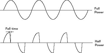
Figure 8.2 IGBT dimmer
The past few years has seen the introduction of dimmers based on IGBT technology (Insulated Gate Bipolar Transistor) (See Figure 8.2). These high powered transistors have become widely used throughout the electrical industry for controlling supply switching, control of motors, battery charging, etc. The most recent development is to replace triacs and thyristors in circuits used for dimming lights. The advantage of a transistor over the thyristor, is that the current can be gradually varied through the device and not just a rapid switch on, as is the case with thyristors. Insulated Gate Bipolar Transistor dimmers allow the power to come on naturally at the beginning of the half cycle, but slowly turn off the current in a controlled manner on the falling waveform. The software controlling the dimmer is designed so that the switch off curve is tailored to reduce the rapid fall time of a thyristor dimmer. The benefits are that EM interference is reduced to a lower level and any lamp sing is virtually eliminated. One aim for many years has been to have a true sine wave dimmer where there would be no rapidly rising waveforms to create the problems associated with other types of modern dimming. The International Electronic Service (IES) of The Netherlands have developed a sine wave dimmer for powers of 3 kW, 5 kW and 10 kW. They are not pure sine wave, but are reconstructed smooth sine waves, using 40 kHz switching control systems. By using a high frequency, there are many steps in each sine wave, therefore it becomes practically smooth in practice. One of the best developments of modern IGBT dimmers is that short circuit protection can be performed by the electronic circuitry. The units will switch off on short circuits. The input is usually controlled by an mcb with the unit providing electronic overload and short circuit protection.
8.2 Problems in practice
Since the inception of modern electronic dimmers using thyristors, etc. all manufacturers have been trying to solve the problem of the chopped waveform and the associated electromagnetic interference. Several ideas have emerged from manufacturers to reduce that interference to manageable levels, and recently have seen the introduction of devices other than the thyristor as the power controllers. Unfortunately at the lower priced end of the dimmer market, the interference is only just contained to the general level set by the standards authority of the countries concerned, and is usually not good enough for professional installations where microphone cables and video cables are used. At the upper end of the market, manufacturers, at a cost, will make dimmers with very low interference levels from the point of view of audio and video circuits. The strict implementation of the EMC Directive by all manufacturers should ensure that dimmer interference is much lower in the future.
In practice, most thyristor dimmers are operated at about 80% of their full output and this is enough to guarantee that we will always have a rapidly rising current waveform which is the switch-on point of the negative and positive half cycles. We hope our readers will appreciate, without going into complicated mathematics that any waveform approaching a square wave, is made up of a multiplicity of other waveforms, varying from waveforms at fairly low frequencies to those at extremely high frequencies and it is the generation of these high frequency waveforms that gives us the most problems.
If we examine the effects of the lower frequency waveforms, we find that these can cause sympathetic vibrations to be set up in lamp filaments every half cycle and if these approach the resonance of the filament itself, we can have quite loud acoustic noises coming from the luminaires, which manifests itself in a high pitched buzzing – colloquially known as ‘lamp sing’.
It would seem on initial inspection that to get around the problem of the wave shape output of thyristor dimmers is almost impossible. However, this is not the case in practice and a very simple trick can be employed. By introducing into the circuit a choke, which consists of a coil of wire wound on a fairly heavy iron core, the rise time of the leading edge of the waveform (the switch-on point) is slowed down and if we effect a change from the normal 2 or 3 microseconds switch on time to around 500 microseconds, then we will have overcome most of the interference problems. More recent developments use controlled switching sequences for the power devices; thus instead of rapidly changing levels in a few microseconds a ramped switching is used to give a much longer transitional period thus producing less interference.
A method of measuring the amount of noise generated is required and the generally accepted standard for assessing interference from dimmers was that introduced by the BBC during the late 1960s which still holds true today. Various groups of people had experimented with measuring the amount of interference generated and the experiments included specific lengths of wire being laid adjacent to the dimmer power cables. Special coils were also used mounted adjacent to power carrying conductors, so to assess the electromagnetic radiation. One of the problems with these methods is that they are much too flexible and have too many variables, i.e. length of cables used, the position of the cables in relation to each other and how do we equate the current flowing with the interference received. Before making any measurements or standards it was necessary to establish the levels of noise that would cause problems in practice. In general, within controlled studio conditions, very few problems occur with the vision circuits – only on the audio.
The basis for the measurements to avoid audio problems was as follows. On the assumption that when a microphone is working at −70 dB, its normal operating point, quite considerable amplification has to take place before the audio signal is processed. It was found at that time that sound desks had a signal to noise ratio of about 50 dB, so a figure in excess of this had to be aimed at to avoid deterioration in the quality of sound.
It is very easy to keep the dimmer power cables away from the audio and vision circuits in the permanent installation, but it is extremely difficult where many flexible cables are used. At the time these experiments were taking place, Star Quad microphone cable with very superior interference rejection properties, came into use. This enabled quite reasonable levels of interference to be tolerated, and thus the dimmer manufacturers weren't presented with quite the problem they originally envisaged.
It should be noted that Star Quad cables have varied over the years, and the introduction of a thinner type of cable with lower rejection limits caused some concern during the early 1980s but does not seem to have proved to be a problem in practice.
To measure the interference accurately, it was decided that the best way would be to wire some form of measuring device into the circuit so that as many variables as possible were removed.
A solid state dimmer, which chops the waveform, when conducting at any level under maximum will generate on its output a string of interference pulses. These pulses are at a maximum amplitude when the dimmer is at 90° conduction. It was essential that the test circuit when placed into the power feeds disturbed these pulses as little as possible, so avoiding erroneous readings.
Ultimately the circuit as shown in Figure 8.3 was adopted as the most effective method of measuring the interference in dimmer circuits. Two main points have to be observed when making these measurements, and these are:
- As any noise generated by a waveform is proportional to its energy content, a method of measuring the rms value has to be used.
- As the test is to assess electrical interference which becomes audible, a method of weighting the reading to the ears’ response has to be incorporated.
The measurement of rms is relatively straightforward as several test meters made by reputable manufacturers are available. Point (2) is covered by the circuit which electrically gives a similar response to the ear. Having decided upon a measuring technique, it was relatively easy to set the levels of permissible interference in the studio.
The measuring circuits have to be adequately encased within metal boxes so that external electric fields are minimised and no stray voltages are present on the meter readings. One other extremely important point is that the source impedance of the electrical supply to the test dimmer and load should be as low as possible because the interference readings may be artificially lowered on high impedance sources.
Having set up the test rig the sequence to be followed is:
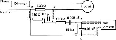
Figure 8.3 Circuit diagram of dimmer test system
- Normal supply volts are applied to the dimmer.
- The control level and hence the ‘switch on’ point of the thyristors is varied to give a maximum reading on the meter, and this generally occurs at a firing angle of 90° with maximum rated load.
To meet acceptable levels, the rms meter readings must not exceed 15 mV rms for 2.5 kW, 3 kW or 5 kW dimmers, and must not exceed 30 mV rms for 6 kW and 10 kW dimmers.
The figures given are for the interference limits in 240 V dimmer circuits. Both 120 V and 240 V systems generate interference, the problem with 120 V supplies is that the current for any given wattage is double that of a 240 V system. As the interference is proportional to the amount of current this will mean taking extra precautions on 120 V installations.
If the power cables going from the dimmer room to any of the luminaires run very close to other cables, then electrical induction takes place, and the ‘rubbish’ voltage from the dimmers is transferred on to all other forms of wiring. This might not be so bad if the wiring is the normal mains system around the premises, but it is obviously extremely bad if it is the vision or audio circuits that are affected. Of course, one of the unfortunate side effects of using a large choke in the output is that the choke itself can cause acoustic interference, and dimmer rooms can become quite noisy places, so much so that it causes problems in the rest of the installation.
8.3 Dimmer types
Dimmers come in various shapes and sizes, the most popular being 2.5 kW, 3 kW, 5 kW, 6 kW and 10 kW. Dimmers are available in two distinct types; those which are ‘wired in’ and those which have ‘plug in’ dimmer modules. Wired in dimmers are usually permanently installed inside some form of container, be it a small portable crate or a reasonably large metal enclosure rather like a filing cabinet. Plug in dimmers are often used where failure of particular dimmer modules causes problems with regard to the progress of rehearsals, transmissions and any live performance.
A plug in dimmer consists of a chassis, which these days may be metal or plastic, on which is mounted the control circuit, made as a removable pcb, the output power devices, which could be either individual thyristors or an integrated circuit power block. Filtering chokes are generally mounted on this chassis, although in some systems, the choke is mounted separately within the dimmer cabinet. When using plug in dimmers, it is important that some distinction is made electrically and/or mechanically in the inter-changeability of units within a dimmer rack. This is to avoid making the mistake of putting a low powered dimmer on a high powered source. One major problem that occurs with plug in dimmers is that of safety. It is obviously important when removing a dimmer module, which may be approximately the size of a shoe box, from a dimmer rack, that operator access to any live terminals is prevented, thus preventing any electrical shock hazards.
Wired in dimmer systems are usually supplied with master printed circuit boards, with the control circuits on it for each of the individual dimmers. The power thyristors or integrated circuit power blocks are usually separate from the mother board. Although a dimmer rack may contain quite a large number of dimmers, it is important that the printed circuit boards control only small numbers of dimmers from the point of view of failure. One master control circuit board failing could be quite disastrous if it is controlling 30 or more dimmers. Control circuits that are common to about six dimmers are preferable. High density wired in dimmers are mounted in cabinets where access is only possible by the use of a key or tool to open the door so that safety is maintained. Small six-way dimmer packs, which are very common in practice, usually have to be dismantled by removing screws and covers to gain access for maintenance.
Dimmer technical parameters
To avoid fluctuations in the light output of the luminaires when controlled by dimmers, it is important that the dimmers are relatively independent of the input voltage variations. Most good quality dimmers made today are usually supplied with ‘feed back loops’ so that the dimmer output is maintained within certain limits (usually 10:1). However, it should be borne in mind that a dimmer only works from the nominated output mains voltage downwards. Unless supplied with special transformers and control circuitry, it is not practical to have a dimmer which boosts the output, i.e. if the dimmer is rated at 240 V output and the mains input is only 210 V it is impossible to make the output any higher than 210 V.
In practice dimmer loads vary considerably and any type of dimmer may be required to work with loads of small power (i.e. our old friend the 60 W practical lamp). It is obviously essential that the dimmer should remain stable on such occasions and not go into any form of variation of output caused by say, internal oscillation. Dimmers are also somewhat abused by the operators and more than likely they will have isolating transformers plugged into them or many other inductive loads. On these occasions, it is essential that the dimmer does not lose its stability or for that matter, draw excessive current which might destroy the output thyristors.
If the output of the dimmer does not have a balanced output, the imbalance will be seen as a small direct current component. It is essential that this direct current is kept to an extremely low level so that it does not cause problems to any of the connected loads or for that matter on the mains supply to the dimmer room. The electricity supply authorities are not too happy with d.c. on their a.c. distribution system.
All dimmers have to meet normal electromagnetic spectrum interference regulations in the country concerned. Additionally, the dimmers must reduce the high frequencies present in the output waveform which would cause problems with the sound and vision circuits in any installation.
It is obviously important when controlling dimmers that the application of a control signal will produce a known response, in practice dimmers are required to respond instantly to any change of the control signal; the only limitation being the lag within the lamp filaments themselves.
A problem that exists with the larger light sources such as the 5kW and 10 kW, is that of ‘thermal shock’, due to the large inrush currents. Modern digital techniques can vary the ‘turn on’ time to allow a build up of power over several cycles of the mains when the channel is switched to ‘full’ thus ‘fading’ the lamp up, although it appears to be ‘instant’.
In the past dimmers were controlled by analogue, d.c. control signals, i.e. the application of a small control voltage from 0 to 10 V d.c. will produce the changes within the dimmer itself. Several disadvantages exist with analogue control signals; first and foremost is that each dimmer has to have one input control wire, thus if a control system of 240 ways is driving 240 dimmers, 240 control wires would have to be used, together with one or more common wires. Today, the application of digital control signals to dimming systems has become the normal practice. Digital control inputs are generally decoded on special cards situated within the dimmer pack and the control signal is conveyed either by co-ax cables or twisted pairs. Thus all the dimmer control signals are fed down one cable, the usual limitation being the digital system and this is 512 channels when using DMX 512, thus two cables are needed if this number of channels are exceeded.
A dimmer will obviously respond in some way to the control signal – that response will be dictated by the needs of the operators. It may be that a rapid fade-up is required over the lower portion of the control channel with a slower progression over the upper portion of the control channel; or the operator required very little light change from the luminaire over the lower portion of the fader characteristic with a large variation when the channel is raised towards its maximum. Dimmers have been made with built in ‘laws’ to cater for various tastes in the entertainment industry for many years. However, in recent times, with the advent of more sophisticated control from modern lighting consoles, it is possible to use ‘linear’ dimmers where the law shaping is done by variations on the input control signals. With digital control, it is possible to set the ‘law’ of the dimmers precisely to the operators’ requirements by adjusting the ‘dimmer programme’.
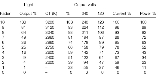
The square of the fader setting gives the percentage light output, as shown in Table 8.1, e.g. Fader at ‘6’ equals light output of 36%.
In practice if we fade on an American system at 120 V or a British system at 240 V, we see little or no difference to the operation of the lighting system. However, if we choose to do comparisons of the parameters concerned, it is important to remember that each volt of variation will produce a change of 10 K degrees within a 120 V dimming system, whereas at 240 V, each volt change produces a difference of 5 K degrees. This is because of the relationship of Kelvin degrees to the current, and for the same wattage load a 120 V system will have twice the current of a 240 V system.
Table 8.1 Square law dimmer control
8.4 Protecting dimmers
As far as the output of the individual dimmers themselves goes these can be protected by either mcbs or fuses.
Many mcbs that are used for circuits with much lower current capacity have fault current ratings of somewhere between 6000 A and 9000 A particularly in the type that we would select for dimmers. It is more than likely that the potential fault current of the circuits involved will exceed these values. It would seem at this point that an mcb could not be used to protect our outgoing circuits, however, in practice this is not the case, because we are allowed to use a device which is not quite adequate if we back it up with a fuse which adequately protects the complete circuit. Thus, if the prospective fault current was 8000 A and the breaking capacity of the mcb we had selected was 6000 A, we would have to back up the mcb with a fuse with a breaking capacity in excess of 8000 A so that the circuit was fully protected.
Before we go any further it would perhaps be better to introduce the term l2t, which refers to the time/current characteristic and is a quantity consisting of the time period combined with the square of the instantaneous current passing through a fuse between the instant when the circuit fault commences and the instant of the fuse rupturing. l2t is often described as the ‘let through energy’. Both thyristor manufacturers and fuse manufacturers publish l2t curves for their devices, and the manufacturers of dimmers simply have to compare these curves to select the correct type of fuse to protect the devices used. It is therefore essential to observe the manufacturers’ choice of fuses for their equipment. Thyristors and triacs will also be damaged if an over voltage is applied in the reverse direction to the normal current flow and in most cases will only tolerate twice the peak value of the steady state voltage. Fuses to protect thyristors and other solid state devices in dimmers should meet the requirements of IEC 269–4 and BS 88 part 4. Fuses for 2.5 kW 240 V circuits usually are 10 A rating and those for 5 kW 240 V circuits are rated at 20 A. Any fuses used should be generally available and not specially made.
The problem with fuses is that, believe it or not, they take a finite time to operate. If a solid state device is rated at say, 40 A, it quite happily carries a current of 40 A indefinitely, and over short periods of time, it will carry currents in excess of 40 A quite safely, however a high current for long periods of time will be fatal for the device. The reason for failure of thyristors is that the semiconductor junctions within the device overheat and ultimately break down, thus if we overload the device well in excess of its normal current rating, for any period of time, we will destroy the thyristor. Therefore our first consideration when selecting a fuse is that it should adequately protect the thyristor circuitry. Additionally, the fuse must be capable of handling the cold current surge of the lamps without failing. Fuses operate extremely rapidly when a very high current is applied; or it might be a low current for a longer period of time. The time can be over the range from a few milliseconds to several thousands of seconds. It is therefore not possible to give the operating time for any specific fuse when the operating time is dependent on the value of the currents involved.
One problem that can occur with dimmer installations is that a 5 kW dimmer may be used to feed a practical light on a set and this practical light may only be a 60 W lamp fed via some lighting flex. In this case, the 20 A fuse would be well over the approved rating for the flex feeding the individual lamp; therefore some form of sub-fusing must take place. This sub-fusing must be inserted at a point in the electric circuit so that it adequately protects the wiring concerned.
8.5 Dimmer rooms and switchgear
If we are designing from scratch, we can obviously make allowance for some area within an installation which would house the dimmers, their racks and the associated switchgear to control those racks. In practice however, any broom cupboard seems to be the solution to the dimmer room. What do we require from a well designed dimmer room?
First and foremost it is space. Secondly, the room has to be either self ventilating or provided with proper means of ventilation. If we have a large area that can be used for the dimmers, it is possible to install dimmer racks containing a small number of dimmers per rack. As most areas allocated for dimmers are small, modern practice is to use high density racks, and these may be up to 192 dimmers per rack. The physical numbers in the rack does not necessarily create a problem, but the weight of the racks on the floor area does. The other possible source of concern is that by using one rack with many dimmers in it, controlled from only one piece of switchgear, any form of breakdown in the main supply would be quite disastrous on any transmissions, rehearsals or live performances. As a general rule, it is better to spread the eggs over more than one basket. Although this requires more pieces of switchgear, because each dimmer rack must be provided with a means of isolation, independent of all the other racks, it is obviously much more expedient from an operational point of view and also from a maintenance point of view. Another snag that occurs with high density dimmer racks, is that all the output power cables going to the stage or studio area have to be terminated somewhere within the dimmer rack itself and the greater the density, usually the greater the problem of termination. If we allow for a waste heat generation of approximately 100 W per 5 kW of dimmer power, it can be appreciated that in a high density rack quite high heat loads are generated. Thus the dimmer racks usually have to be force cooled by fans mounted within the racks, and in fact in one installation seen by the authors in America, the degree of cooling required in a room with several high density racks was so great that it was difficult to close the dimmer room door against the gale!
Dimmer racks will be designed for either single-phase input or three-phase input and this could be either by cables or some form of busbars. The dimmer rack itself should preferably be no higher than 1.8 m so that access to the rack is feasible without the use of steps or with the operators having to over reach, which in itself is dangerous. It is obviously easy to have the control and power connections made when there is access from the front of the rack together with access from the rear. If rear access is required, allowance must be made for additional space within a dimmer room as the rear access would no doubt have an opening door and a clearance of at least 600 mm must be provided. Many modern dimmer racks have front access only but the problem of front access is that all the input and output terminals must be accessible and this often involves the manufacturers in some conflicts of interests with regard to space within the rack. Where small dimmer racks such as six-way packs are used, the problems are not so acute, although each of these racks would have to be provided with a small isolator adjacent to the racks for safety reasons. Dimmer racks have to be clearly marked because there will be several circuits within a rack, all with fuses or mcbs which must be clearly marked. The dimmer racks must also have indicators which show that power is supplied to the rack and each individual dimmer must have some form of indicator to show that it is live. It is important that any form of earth leakage should be detected, although this is not usually provided on small dimmer racks. It is preferable that some kind of overheat detection is supplied within larger racks and this can be for two purposes. To detect firstly the generation of fire, and secondly the generation of additional heat which may be caused by fan failure within the racks. Although not a large danger within the premises, it may be that the failure of the fans causes the individual dimmers to fail by becoming excessively hot subsequently causing the semiconductor devices to fail.
It goes without saying that all dimmer racks have to meet high electrical and mechanical safety standards. Any form of electrical apparatus built within a rack or chassis system has to meet the requirements of the country of manufacture and also the country in which it would be used.
On the surface it would seem a very good idea to employ a residual current device (RCD) formerly known as an earth leakage circuit breaker, with a very low sensitivity (30 mA/40 msec)on the output of each dimmer which would ensure that any operator coming into contact with either of the live wires, i.e. the phase or the neutral, would be safe. Evidence exists that would indicate that any RCD must be carefully chosen so that it operates almost independently of the dimmer output voltage levels. A point to be watched is that RCD manufacturers don't necessarily endorse the use of their products when used with dimmed, chopped waveforms.
It's no good having a nice looking dimmer rack where, when faults occur access for maintenance is a nightmare. It is particularly galling to any operator to find that to change the simplest of components requires minutes and sometimes hours removing screws, nuts, washers, panels etc. often cutting one's hand in the process, accompanied by the usual quietly mouthed expletives. For ease of maintenance it is obviously essential to have good technical information which gives circuit diagrams, constructional details of the cabinets and a complete set of instructions of how to go about maintaining the equipment itself, and this must be totally unambiguous. Much modern equipment however, is quite sophisticated and any maintenance, other than first line, would probably have to be carried out by the manufacturer, but this usually entails extra expense when calling upon a service engineer from the manufacturer concerned.
8.6 Distributed dimmers
When dimmers were controlled by analogue signals, a centralised dimmer room was installed. The amount of cabling involved to have dimmers placed all over a studio grid, for example, would have been quite inhibiting to the normal operation. With the advent of DMX control, it is now possible, by using one very simple cable, to control many dimmers throughout the installation. Combined with the reduction in weight of dimmers, it is possible to either place dimmers on the lighting bars themselves, or integrate them into the luminaires. As most studio premises these days are equipped with vast quantities of dimmers, it now makes sense that the dimmers could be integrated into the lighting bars. Thus, if there were three outlets which in the past were fed from the dimmer room, the three dimmers could now be integrated into the assembly above the lighting bar itself.
As an example let us see how we can feed three 5kW channels which are 50 m from the dimmer room. If we use conventional dimmers, we would require a circuit capable of taking 20.833 A at 240 V or 21.74 A at 230 V. The maximum volt drop we are allowed is 9.6 V. If we are using PVC cables in trunking, we could use 6 mm2 cable with a current rating of 41 A. The voltage drop for 6 mm2 cable is 7.3 mV per A perm; so for 240 V we have a volt drop of 7.6 V, which is well within the specified voltage drop limits. For an applied voltage of 230 V we would get a voltage drop of 7.94 V, which again is within the capability of the cable. However, in a normal dimmer installation, we are feeding several circuits down the trunking, therefore we have to apply a grouping factor. If we assume there are 20 active circuits down the trunking, our correction factor for grouping is 0.38, which means we are looking at a cable capable of taking 53 A. This means we will have to increase our cable size to 10 mm2. The advantage is that we get less volt drop going to the luminaires from the dimmer room. If we now take the case of a triple 5 kW pack of dimmers in the studio, being fed by one cable, we require a cable taking a load current of 63 A. This fits in well with having a 63 A mcb protecting the circuit. For a single-phase feed to this dimmer pack, the cables selected would be 16 mm2 capable of 76 A. The volt drop is only 2.8 mV per A per m, so the overall volt drop would be 8.28 A which is within our 9.6 V maximum voltage drop. If however, we group these feeder cables in trunking, we would then have to supply a suitable grouping factor. If we assume we are feeding three dimmer packs giving total dimmer outlets of nine, we would have to apply a grouping factor of 0.5 which means that the cables would have to be rated for 90 A, which means that we are required to install 25 mm2 cable for each feeder to the dimmer packs. All the previous calculations are based on using single-phase a.c., but if we were using three-phase cabling within trunking, the current rating would be reduced slightly for all cables. The 25 mm2 cable would still suffice for the triple dimmer pack. In the case of the single circuits, we would have to increase our cable size from 10mm2 to 16 mm2. All of these calculations are based on all circuits being fully loaded. However we are allowed to reduce the cable size if, in fact, not all the cables in a group are used simultaneously, and generally in film and TV studios, this may be the case. All modern dimmers are capable of being selected as a numbered channel on a DMX decoding system, and in the case of distributed dimming, it is relatively easy to change the channel number controlling a dimmer in the studio.
8.7 Control systems
In the days of resistance dimmers, control of lighting was slow and cumbersome. The cues were accomplished by the electricians making several dimmers move in unison for effect and even to move one dimmer was a considerable task. The main problem being that the LD was not in control of the lighting system at all.
Eventually Strand Lighting introduced electrical controllers, driven from a rotating mechanical shaft system, that allowed the amount of current fed to the luminaires to be varied. The most famous of these were auto transformer dimmers which were driven by an up/down clutching system driven by a variable speed shaft drive arrangement. The system was relatively slow in operation and produced good fades but not as swift as those accomplished today. These earlier systems generally were ‘two pre-set’ which allowed two states for each dimmer, according to which of the pre-set channel controllers were in use. The consoles were provided with master controls for over-riding the pre-set states, so that fades could be accomplished with groups of lamps.
One of the drawbacks with systems such as these, was the fact there were no memory systems which memorised the on/off state of the channels – thus groups of channels could not be switched on and off at will. Strand Lighting came up with an ideal solution for the time by using the technology from the organ builders and pictures of old control boards looked like the consoles of cinema organs. The system of memory was extremely simple inasmuch as a small flexible contact pin was allowed to engage in a movable bar with contacts arranged as small notches along the bar, thus offering low voltage control of the particular channel and upon selection of the appropriate notch bar, would bring into play the group of channels. As can be well imagined to have many memories meant that the system required a multiplicity of contact pins and several notch bars, thus this type of console was usually limited to about 40 memories on the red pre-set and 40 memories on the blue pre-set. It was not uncommon in the early days of memory systems that the operators had to re-plot major portions of the action to take advantage of the memory grouping facilities. One problem associated with memory control in those days was if you didn't release your foot at the correct moment off the ‘pre-setter’ pedal on the console, you were in great danger of having a random selection of pins in the notch bars which caused rather a lot of soul searching by the operator concerned.
One of the biggest steps forward was the introduction of solid state dimmers, which allowed voltage control of the dimmer directly from a console rather than control via the electromechanical system. These lighting consoles were hard wired systems where the voltage or current output of a fader was taken down one individual wire to control a dimmer, using a common return. As has already been noted, the saturable reactor system allowed direct control but unfortunately the memory systems were extremely primitive when using this system.
Up to the late 1960s the majority of lighting control systems were based on a fader directly controlling a dimmer. In 1967, Tony Isaacs of Thorn Lighting devised a new type of control system, using logic circuits. These circuits were extremely crude compared with today's silicon chip devices and were constructed from germanium transistors, resistors and capacitors. The memory system was based on a ferrite bead matrix where a series of these beads carried the ‘0’ and ‘1’ magnetic information to give channel level and on/off instructions.
This console was capable of memorising several levels from one channel. For the first time a control system worked by sequentially scanning each piece of channel control information, from a dedicated controller capable of controlling any channel number input from a numeric keyboard. Whereas systems before this relied upon the setting of a fader; the fader on the Thorn console could be used to set one channel level, which was stored and another channel selected and another level set. This also allowed a multiplicity of levels for any single channel. The faders were servo coupled and always followed the selected channel level. The amount of group memories was limited purely by the fact that the ferrite bead matrix memories were expensive and difficult to construct. The original system comprised rather a neat control panel but tucked away in a little room adjacent were four bays of equipment. With the introduction of integrated circuits, the system reduced to two bays of equipment, but was very large when one looks at a system today where the actual electronics is no greater than that contained in a PC.
The Thorn system had dedicated control panels and not long after its introduction Strand introduced the MMS (modular memory system) console, where individual components of a console could be blended to give different alternatives for the various customers.
Changes between one lighting state and another can be incredibly complicated with variations of the speed of fade down or fade up of the lights all intermixed to provide a variety of effects, and all these can be programmed to be accomplished very quickly or very slowly. Due to the advances in microprocessor design and the use of PCs, it is possible to make relatively cheap lighting systems with an incredible range of facilities. Modern memory systems now have to control the intensity and colour of the light, and additionally the position of the luminaire and all its beam pattern and shaping functions.
Many consoles today are based on Pentium processors and these enable a lighting console to be fitted with the necessary hardware to cover for all eventualities and the software programme of operation, can be changed so that the desk operates in different ways. An important feature of consoles is that any operation should give a predictable result, therefore not confusing the operator. The ergonomics of design of the controls and their placement on a lighting console is extremely important; the physical size should be kept as small as possible so that one operator can get to all controls with relative ease. Due to the various operating philosophies adopted in different parts of the world, it is now possible for consoles to be programmed to take into account the customer preferences as to the way they wish the console to respond to their commands. Even consoles have entered the magic world of ‘the net’. By using network systems it is now possible to access the control signals from various points on the network. In the past, distributed signals around a production area probably involved several multiway cables, co-ax cables and various other types of cables to accommodate the data necessary to provide remote control and remote viewing of console outputs. By using a modern network system it is possible to use one high grade cable system with the necessary termination points fitted and all signals run through this system. Previously, a LD and possibly the assistant, would have to draw on a large-scale plan the lights that are required, the various gels that may be used and the positional data for all the luminaires. Having done all this preparation, it was then necessary to transfer all this information to the lighting console when in the production area. Today, by using off-line editor programmes, which are capable of running on a fairly average PC, it is possible to prepare the production lighting and adjust all the necessary effects and balances, where this is possible, and to record them onto a disk which can then be used in the lighting console. Having recorded the necessary memories and any effects to be used, it is possible for them to be replayed in real-time on the PC and its associated VDU. It should be noted that the use of an editor does not necessarily give the positional information of the lights; this more than likely will still be prepared on a good old fashioned piece of paper.
Some companies now produce Windows based programmes which provide a virtual lighting console on a PC. To keep the screen information to manageable levels, it is possible to select on the VDU several different pages of pre-sets together with their master controls, e.g. channels 1–20, channels 21–40 etc. A drawback when using a ‘mouse’ is that you may be unable to independently move individual fader levels up and down at the same time. One advantage of this system is a small number of channels per page with the ability to change pages rapidly to gain access to other channels; although to simultaneously gain access to channels spread over several pages may be difficult and time consuming.
Although many modern lighting consoles are rather daunting in appearance, they still have to provide the following basic functions.
1 To be able to set the channels and hence the dimmers anywhere from zero to full light output.
2 The ability to switch a channel on or off at any level of its fader setting.
3 To group channels together.
4 To mix either individual channels or groups of channels together.
5 The ability to over-ride channels by ‘Master’ or ‘Group’ faders and by master switching.
6 The ability to collect the channel information which would be its fader setting and/or its on/off condition; either as individual channels or in groups or combinations of groups and consequently store in some form of memory system.
7 To be able to rehearse complicated fade sequences involving groups of channels or memories in a timed sequence and subsequently record this information.
8 To be able to recall settings, change them and re-record the result.
9 To replay the information stored in memory either manually or automatically in a sequence to suit the action.
Lighting consoles come as three distinct varieties, the first being the manual system, where each channel is individually fed from a fader; the second system is that of an ‘enhanced’ manual system where several faders are employed together with a very simple memory control so that the channel settings can be memorised and replayed and some or all of the faders can be re-used for other purposes. The third type of system is the fully automated control system where channel selection is invariably by a keypad; there are only one or two channel faders employed and these may exist in the form of a wheel rather than the traditional lever. The control console will have a memory system where anything is possible, and effects systems are built in (see Figure 8.4a,b).
Generally, in a manual system each channel is directly fed from a fader, thus a simple 60-way system uses 60 faders. If the system is two pre-set, this means that two faders are provided per channel with the ability using two pre-set master faders, to fade between either one of their preselected states; the highest of the selected states taking precedence when the two masters are fully on.
For example, channel X is set at ‘7’ on the red pre-set and ‘5’ on the green pre-set. With the red master ‘up’ and the green channel ‘down’, channel X is set to ‘7’; when the red master is ‘down’ and the green master is ‘up’, the channel is set at ‘5’. When the red master is at ‘full’, raising the green master to full will not change the state of the channel, as the red channel is the highest, the output will always be ‘7’. This gives simple twin-state (or pre-set) mixing. The state of each channel can be easily set on the lighting console and an over-riding master facility is available. For simple productions and the control of lighting of many types, this console is more than sufficient and generally is very fast in operation, as channels are very easily accessed. Most manual systems these days have a control where the cross fade is usually dipless, i.e. there is a small amount of electronic control which provides for a smooth fade progression between the two pre-sets.

Figure 8.4 Lighting consoles (courtesy of Electronic Theatre Controls (Europe))
Small installations will use consoles with 12, 24, 36 or 48 channels and these are usually fairly simple two pre-set manual consoles, with one channel fader dedicated to each dimmer. One of the drawbacks of manual systems is that you cannot have more than two states of each channel with two pre-set systems, because otherwise you have to reset the fader lever.
The next step up from a basic, manual console are those where a limited memory system is also available. The method of recording a lighting scene is usually to use a specified pre-set of channel faders to set the various levels and when the scene has been lit, the submaster is then memorised, and this then records the current lighting state, allowing the next scene to be set up using the same set of faders, because of the enormous memory capability, it is now possible to set up several hundred cues which may be very subtle changes to the lighting states, but it enables the lighting designers and their assistants not to have to keep notes, as was the case in years gone by. The only thing needed now is an accurate cue sheet to ensure that the right lighting is selected at the right time during the production.
We finally come to the all singing, all dancing, memory control systems that exist today. Generally the system will have at least one or two channel controllers, each one of these having the ability to control any channel. It will also be quite possible that memories and groups may be introduced into the main system via the channel controller. Consoles of this type work on the principle that we select a channel on the controller, the level is set and stored away and we now move onto the next channel to be controlled. Thus systematically, one by one, we assign levels to the lights concerned, either on stage or in the studio. As the channels are switched on and the levels are set, we slowly build up the lighting within the scene. At the end of this period, it is possible, by using the memory system, to store all the channels at their various levels for future use. One advantage of this system is that if the same lights are used for a further piece of action within the scene, the LD can set completely independent levels from those already memorised without ever considering the information stored away. The control system does it all for him. To replay the scenes that have been memorised, they are usually recalled from the memory system by the selection of the appropriate buttons and subsequently played back via the master controllers which enable either cuts or fades to progress. Memories may also be added or subtracted and multiple effects can be combined before being introduced into the lighting output. Additionally, consoles provide facilities for controlling automated luminaires.
Talking to most operators, we generally find that they prefer a fader per channel which gives instant access, particularly on live events. One big problem with us humans is that we like all the little frilly extras that exist on any pieces of equipment. One of the difficulties that exists with very sophisticated consoles is how fast can the operator respond when a problem occurs. Is it really necessary, or so it seems, for the operator to require a science degree to be able to understand and operate many modern lighting consoles?
There is a tendency by manufacturers, because of the competition within the industry, to provide every ‘bell and whistle’ possible within their control system, the main reason being that they do not want their product to look deficient in any way. Quite often ending up with a console trying to be everything to everyone. There is a confliction of interests between the TV industry and their requirements; the theatre industry and their requirements and the ‘pop’ industry and its requirements. It is very difficult to have a hybrid lighting console to bridge the gap, and invariably we end up with the horse so designed that it turns out to be a camel!
Advantages however, do exist with modern consoles, inasmuch that effects can be immediately accomplished, without much of a problem. Most modern consoles have integral soft patching systems, which allows the control of many dimmers usually via a smaller number of control channels. They also have the ability to shape the input control characteristic of the dimmers themselves, thus different shaped characteristics can be provided for lamps that respond rapidly when switched on, such as 1 kW profile spot luminaires, compared with the 5kW and 10 kW which have a much slower response time. It is now possible, within complicated fades, to tailor the curve of each individual light to gain a most harmonious result.
A typical modern console allows control of 512 channels, 60 channel faders, 450 memories, 15 active playbacks.
The channels can be allocated as Highest Takes Precedence (HTP) or Latest Takes Precedence (LTP). The console provides for:
- any channel to control multiple dimmers,
- individual response curves for each dimmer channel, and
- patching of dimmer and colour changers by typing a DMX number.
It is possible to arrange the functions of automated luminaires so that they appear on certain faders in a defined sequence. The console shows:
- channel output in % and 0–255 steps,
- DMX512 output levels,
- channel usage with luminaire name (e.g. Superscan),
- patching information,
- preview of memories,
- preview of sequences and chases,
- chase speed and cross-fade settings,
- sequence information, and
- fade progression and other items of information to help the operator.
If we buy a console from a manufacturer together with that manufacturers’ dimmers, no doubt they will nicely work together. However, this is not always the case when we would desire to buy dimmers from one source and a lighting console from another. It is absolutely essential that the console talks intelligently to the dimming system. In the days when systems used analogue d.c. control signals, this was more than likely possible, although over the years manufacturers all had their subtle variations, around a 10 V d.c. theme. With the advent of digital control systems, it is important that the digital signal is recognised by the dimmer units.
Although the lighting console is ‘remote’ from the dimmers in most installations, the term ‘remote control’ usually refers to additional methods of control other than the main console. Two types of remote control of dimmers are required. The first being a fairly simple type of remote control which generally consists of switching dimmers off and on only, which is used for rigging purposes by the electricians within the installation concerned. This might be a large panel mounted on the wall in a studio and often called ‘an electricians panel’ or it might be a small hand held controller. It is now possible to provide a ‘mini console’ adjacent to the studio winch control panel for use by the studio operatives.
The second, which is the LD's control, is required to be virtually an extension of a complete working console, thus enabling the LD to sit either in the stalls, or conveniently stand within the studio and plot his lights at first hand. Designers’ controls generally will give access to all the channels and memory system.
If the power input to the installation fails the dimmers will not work and of course we have lost the ability to control them. If however the main lighting console fails what would we expect to be able to do? Possibly the best form of back-up system is where we virtually duplicate all the console facilities, and in fact, in some systems, this is actually done, although obviously at some premium. The biggest loss of facilities is when the memory system itself fails, because of the reliance upon the memory system to store all the channel information. In general, back-up systems are not really used with manual control and enhanced manual control systems, but are only used with the more sophisticated consoles. Obviously where a lever per channel is the operating method, the actual memory system is the fader itself. The most advanced back-up systems in use today allow for a monitoring of the main system and recording constantly all the channel levels to update the system in event of failure. If the back-up system allows for the selection of the memories together with some grouping and the ability to fade up and down from its master faders, then it is unlikely that the audience will notice any major differences.
DMX 512 is a world-wide standard signal which allows lighting consoles to send information to dimmers. The intensity level is sent as a digital code, using an 8-bit number providing 256 levels from zero to full intensity. In addition to controlling dimmers, it is also possible to control colour changers with DMX data sent to each unit. DMX signals are also used to control automated light sources and smoke machines. One DMX cable can transmit 512 individual data signals, each having a unique address number. Therefore, 512 addresses can control 512 dimmers. A motorised luminaire used for effect will probably have several attributes being controlled; if we use a channel of DMX for each attribute, we will obviously soon run out of control signals within DMX512 control cable. Complex lighting rigs will use several DMX 512 cables to feed all the luminaires.
Typical attributes of an automated luminaire are as follows:
- Intensity
- Focus
- Iris
- Colour
- Cyan dichroic
- Magenta dichroic
- Yellow dichroic
- Gobo
- Rotating gobo
- Pan
- Tilt
- Speed
- Reset
8.8 Electromagnetic compatibility (EMC) Directive
If every piece of electrical apparatus in the world only used a sinusoidal waveform there would be no need for the EMC Directive. We are only too aware of the clicks generated by the refrigerator switching on and off affecting our radios; the buzzing noises from fluorescent chokes and if one takes a medium wave radio close to a PC, rather nasty noises emanate from the loudspeaker. Although these manifestations of electromagnetic disturbance are annoying, they are not necessarily in themselves, dangerous, however, in a world that is now full of radio communications and telecommunications networks, it is important that any forms of interference do not interfere with the safe working of systems. For many years several standards have been applied in the United Kingdom for the reduction of radio disturbance from household electrical appliances, portable electric tools, fluorescent lamps and luminaires and broadcast receivers and associated equipment.
The EMC Directive seeks to ensure that any electrical/electronic equipment throughout Europe adopts certain standards to define the permissible electromagnetic disturbance levels that the equipment is liable to generate. The Directive is extremely important to the lighting industry mainly because of the dimmers we use, the consoles and the discharge lighting all of which are quite complex electronic pieces of equipment and all capable of generating some form of electromagnetic interference. Additionally, mechanical equipment used is also controlled by electronic systems and it would be dangerous if these control systems suffered interference in such a way as to affect its performance.