
7
Lighting suspension systems
7.1 Suspension and why it is needed
In TV and film studios, the majority of lighting is placed at a reasonable height above the acting area. The reasons for this are quite simply that we do not wish the acting area to be full of equipment, additionally the floor area is also cluttered with cameras and sound booms.
When gas lighting over the stage was introduced it consisted of a 1.5 inch bore steel gas pipe with rat tail burners fitted along its length every few inches across the whole width of the stage. The pipe was suspended from steel ropes and fed by flexible hoses from the sides of the stage. It is interesting to note that 129/32 inch (48 mm) is the outside diameter of a 1.5 inch steel gas pipe and this was adopted as the standard for the industry. Ultimately theatres used the redundant gas pipes to hang their brand new electric lanterns.
The film industry tend to use single lights suspended by hemp ropes from block and tackles mounted on steel beams in the roof. On occasions, a platform with hand rails (called a ‘boat’) is suspended from two or more block and tackles above the studio so that the additional lights attached to its side rails could be attended by the electricians. Some film studios use long barrels to suspend lights. It is worth noting that the film industry tends to work from the studio floor ‘up’, as opposed to TV which works from the ceiling grid ‘down’.
In 1936 when the BBC started TV transmission, all the lighting equipment came from theatre and film manufacturers, mainly using the rigging techniques of the film industry, such as hemp ropes and block and tackles.
By 1956 the BBC had introduced a motorised hoisting system for lighting, comprising a unit with a motorised gearbox and wire ropes to suspend a 2.4 m long, 48 mm diameter barrel.
With the introduction of commercial TV in 1955 a new type of suspension system had been designed, which consisted of an overhead walkover grid at high level with slots, running the length of the studio into which telescopic suspension units were placed and winched down to the required height from the grid.
Starting from this date, an argument ensued and persists of the merits and disadvantages of motorised barrels versus single point suspension. The motorised barrel protagonist will insist that the saturated lighting rig with two or three lights on each barrel provides enough choice of lighting positions and can be rigged from the studio floor at the same time as other trades are working on the set in comparative safety; whereas a single point suspension installation requires men to be above the grid for rigging. The LD, working in a single point suspension studio, will argue that he can be more precise and can place the luminaire of his choice at the point in space where he wants it, with independent height control of every luminaire.
7.2 Grid systems
The dictionary defines a ‘grid’ as a grating, a gridiron, a framework. It is also described as the ‘framework above a theatre stage from which scenery and lights may be suspended’. The original theatre grids were usually wooden platforms suspended from the roof structure, providing a working level for men to walk over. The floor, which was slatted, provided a means by which ropes or scenery could be suspended. Additionally, the lighting bars were suspended from this platform.
In TV, the term ‘grid’ usually describes the roof structure that supports the lighting systems installed and these can be from very simple fixed barrel rigs to complex monopole grids. The TV industry tended to follow the example of the theatre, due to the need to suspend lights and scenery. The film industry has traditionally always built scenery from the studio floor upwards and any rigging of luminaires is usually done by block and tackles, suspended from RSJs at high level.
In a TV studio where motorised units are installed, the basic need to walk to the units installed at high level can be met by walkways adjacent to the units. However, some organisations have made the entire area at high level completely uncluttered by using self-climbing units, thus allowing unrestricted access to almost any point above the acting area. Monopole grids do require access by staff to move the units. One of the problems associated with walkover grids is that of safety. Obviously, no object must fall from the grid with personnel working on the studio floor and to this end, either pocketless overalls are worn by staff or any items that can be used at high level are usually attached to devices to prevent them falling through the grid slots. Arguments ensue all the time as to the viability of walkover grids, bearing in mind safety legislation, and most studios generally provide maintenance access only. The alternative to this safety problem is to clear the acting area of all other staff. Unfortunately this is time consuming and raises the operational costs.
The most basic design of grid from which we can hang a light consists of 48-mm diameter metal barrels suspended above the acting area. The height will generally be fixed although the use of spring pantographs or drop arms can be advantageous. When the lighting requires adjustment, steps or ladders have to be used to provide access to rig and derig the luminaires. If the position of the luminaires is correct then pole operated controls enable adjustments to be made quickly without much disturbance to the rehearsals. Power sockets are usually distributed in a uniform manner just above the fixed barrels.
To give more flexibility, at a low installation cost, a roller barrel system is often used; this allows barrels, about 2 m, long to run along a set of parallel tracks mounted at high level in the studio. It is usually the practice with this type of installation, to mount the trunking with the power sockets attached, between the trackways. As this requires the minimum of space, the trackways can be installed very close to each other, subsequently allowing the luminaires to be positioned with a high degree of accuracy. It is essential that the moving barrel units are provided with trolleys designed so that they run smoothly along the trackways when pushed or pulled at any point on the barrel unit. There is nothing more annoying to the operator than pushing a roller barrel along the trackway only to see it jam and then having to waste time and effort in moving the unit once again. It is often advantageous to fit a brake to the barrels so that they maintain their set positions in the studio.
The barrels must be installed so that they cannot be removed from the trackways without the use of tools; otherwise a hazardous situation can occur. This system, which allows very good positioning in the horizontal plane, still suffers the drawback that unless additional equipment is provided, the height of the luminaires is fixed. Also, when the barrels move over a reasonable distance, some plugging and unplugging of the feeder cables would have to take place due to the fixed socket arrangement. It is normal practice with the roller barrel system to suspend each luminaire from the barrels by a roller trolley, therefore movement in two planes is achieved. To make the system even more flexible, the luminaire can be suspended by a variable pantograph from the barrel trolley, giving a high degree of flexibility in three planes.
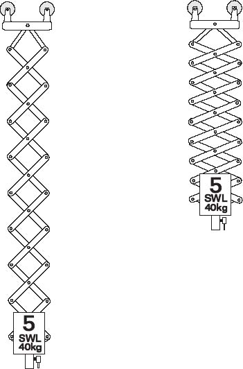
Figure 7.1 Pantograph
A system of suspension that has achieved a reasonable degree of success, is the use of pantographs, mounted on roller trolleys and moving along long single trackways. This gives extremely good height flexibility and when the trackways are positioned as near to each other as possible, also offers a very good coverage over the acting area; the spacing between the trackways is dictated by the maximum size of luminaires used in the installation. The system can use spring pantographs where the height can be easily adjusted by pushing the unit up and down (Figure 7.1). Spring pantographs are balanced for the load of the luminaire and the major drawback is that special safety precautions have to be taken when changing luminaires on spring pantographs. It is preferable to use wind-up pantographs which are not load dependent and thus safer. Horizontal movement is accomplished by dragging or pushing the pantograph top trolley unit along the trackway. The power feeds to the individual pantograph units are often provided by a catenary cable system, rather like those used for overhead cranes. A modern advance, favoured by some large broadcasting organisations, is to use motorised pantographs where the height is adjusted by motor driven wire ropes and the horizontal movement accomplished by a motor drive onto the trackways. Catenary feeder cables for both the control system and the power system are essential. The system can be easily adapted for remote control and has the great advantage of overcoming the safety problems connected with spring pantographs and is very quick and easy to use.
The above systems have mainly allowed only one luminaire to move at a time. When we wish to move more lights at the same time, the systems become mechanically more complex. The most basic of these systems is to use a long barrel with the adjustment of height made by a counterweight system. In the theatre, these consist of very long barrels up to 10 m long, slung from several wire ropes. The lights are all at the same height and the weight on the barrel can be considerable when the power cables are attached. The counterweight system allows for the weight of the barrel, plus all the luminaires and cables mounted on it, to be balanced by a selection of special iron weights and provides an easy method of raising and lowering barrels with heavy loads. Counterweight barrels are mainly used in the theatre; although they have been used in some TV studios, they cannot provide the flexibility of other systems for this application.
An advance on the counterweight systems is the provision of motorised barrels. The motor unit can be separate from the barrel unit, or in the case of self climbers, integral to the barrel unit. The barrel itself is over 2 m long and enables several luminaires to be placed side by side along the bar. Power is provided by fixed sockets, mounted on trunking along the barrel so that the luminaires can be easily plugged into the lighting supply. The adjustment of height is totally flexible and the system inherently safe by its design. It is very easy to operate from a remote control.
Finally, we come to probably the most accurate lighting positioning system of all. The mono-pole grid, although expensive to install, allows monopoles to be positioned about 600 mm from each other in adjacent tracks and individually to be placed anywhere along the trackways. The height of the monopoles is either adjusted by personnel at grid level, using portable drive tools, or by remotely controlled integral drive motors. The main drawback of monopoles is that a reduction in the number of units used in a studio for economic reasons means more physical movement of the units themselves and this requires riggers working over the acting area, which with modern safety legislation, dictates that special arrangements have to be made. It is difficult to move the units in the grid area if they are permanently cabled so the electrical system has to be designed to cater for multi-positional use, allowing the units to be connected as necessary.
When discussing more sophisticated lighting suspension systems, there are certain items that are common to either monopoles, motorised barrels or motorised pantographs. If we cover the ground rules for the component parts, the understanding of the complete pieces of equipment becomes easier.
It is difficult to state which items have the most importance due to the reliance upon one another for the satisfactory operation of particular items of equipment. However, to stick our necks out, we plump for the electric motors first as without these we have to resort to muscle power.
Most modern barrel winch units today employ three-phase electric motors of about 1–1.5 kW rating (Figure 7.2). They also have a combined gearbox. The gearbox will have reduction gears so that the barrel unit moves up and down at a reasonable speed which is usually 8–10 m per minute. The gearbox is selected so that when maximum weight is applied to the barrel and the electrical system is ‘off’, the unit will not move, thus providing a self sustaining system of gearing. To prevent the barrel unit over-running when being raised or lowered, an integral electrical braking system is installed on the high speed side of the gearbox. This brake is normally applied and only released when the motor is activated. Monopole motor units may use three phase, single phase or d.c. drive motors. Because a monopole has a maximum lifting capacity of about 60 kg only compared with a barrel of about 150 kg, the motors are generally smaller. It is easy to reverse a three-phase motor but single-phase motors have to have special drive circuits to allow forward and reverse operation. If d.c. motors are used, although they allow very easy control, they may present problems by becoming generators and supplying harmful voltage back into any control circuits. With any of the systems using motor drive units, it is essential that some form of manual drive is available in the event of electrical failure of the system.
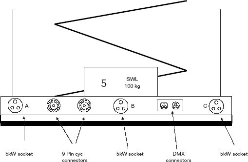
Figure 7.2 Motorised barrel
There are two basic types of winding drum. The first being the scroll drum where the wire rope is wound on side by side in much the same way as a cotton reel. Due to the length of wire rope, together with the need to keep a low torque on the motor, the drums are usually reasonably small in diameter (200 mm approx.) and as only one turn of rope is used around 250 mm wide. It is important that the drum width is held as small as possible so that the horizontal angle where the wire rope meets the drum is kept within certain limits. Usually a groove is formed in the winding drum so the rope follows the correct path. A big advantage of the scroll drum system is that the speed of the barrel unit remains constant when being raised and lowered.
The other type of winding drum is the pile wind and this works rather like a large yo-yo. The rope is piled singly, several layers thick upon itself between two substantial metal plates. This means that as the effective diameter of the drum is changing as the rope piles the barrel unit's speed of travel varies from its highest point to its lowest. A problem for the designers of pile drum systems is that the torque is not constant and the system has to cater for the worst case, which is when the barrel is at its highest point where the pile drum provides maximum speed with reduced lifting ability. This means that larger motors have to be used on pile wind winches than will be used on a scroll drum winch of similar lifting capacity. The system also suffers from the tendency for the ropes to be easily damaged if the mechanical design is not of the highest quality particularly if the retaining plates on the pile drum are weak. With both scroll and pile wind drums the wire ropes have to be very positively anchored to the drum and two clamps are used for each rope. To ensure a margin of safety, a minimum of two turns of rope must be left on either type of drum when the barrel is at its lowest operating point.
It is preferable on self climbing winches to use scroll drums because, by keeping to a low torque, it will also enable the motor to be smaller – with obvious benefits. With a self climber, having the motor unit positioned approximately in the middle of the bar, with scroll drums either side, means that the unit will be wide and this might prove to be a problem. In practice, this does not appear to be the case. As an alternative it is possible to use scroll drums positioned so that they lay in the same direction as the barrel, but if this is used, precautions have to be taken to make certain that the unit, when winding up and down stays in the same vertical plane. Also, there is the danger that the motor unit sticks out to one side and causes an out of balance condition. It is very normal with self climbing winches to use four wire ropes to enable a better balance to be achieved and to meet current safety standards.
Diverter pulleys (used to guide the wire rope to the correct plane) which are generally made from steel for strength and durability consist of a grooved wheel running on bearings. When the wire rope leaves the winding drum it has to be guided via the diverter pulleys to the correct position. The diverter pulleys are grooved and it is important that the wire rope fits snugly in that groove. The diameter of the pulley is also important due to the wire rope having a minimum quoted bending radius so that damage to the rope is avoided. Current regulations call for a diameter not less than 20 times the ropes’ thickness. The pulleys must run on properly lubricated bearings due to the high mechanical loads involved, and to keep noise to a minimum. As a general guide each diverter pulley in the system will reduce the lifting capacity by between 2% and 5% dependent on the type of bearings used.
Barrel winches normally have two ropes, each capable of supporting at least six times the total applied load. Self climbing winches generally have four wire ropes for suspension, however the rules for the breaking strain of the ropes remains at six times total load for each rope.
Monopoles and motorised pantographs which could be operated by a single wire rope, have to be provided with twin lifting ropes for safety. Each single rope must support the total load of the monopole or pantograph in event of failure of either of the two ropes. The minimum breaking strength of each rope must be able to cope with at least six times the safe working load (SWL) plus the weight of the suspension tubes and electrical cables. In the event of a single rope failure, free fall via the rope length compensator system should be no greater than 12.7 mm. It is extremely important that in practice wire ropes do not become frayed and damaged. If a wire rope gets nicked or crushed it is vital that the rope is changed.
Various functions on the motor unit have to be made automatic to avoid either damaging the equipment, or more importantly, injuring staff. The functions are as follows.
Limit switches generally consist of a striker which is driven along a finely threaded shaft towards a microswitch which activates a relay and switches ‘off’ the power to the motor. Rotational movement of the strikers is prevented by a retaining bar which is placed in slots on the strikers themselves. To adjust the strikers, the bar is simply raised and the striker is screwed along the thread to the pre-set position desired and then the retaining bar is replaced. The threaded shaft which activates the strikers is driven from the main gearbox usually by a belt, chain or set of gears.
A ‘top’ switch which will automatically disconnect the motor supply when the lifting assembly is raised to its highest set point. To avoid straining the motor gearbox, the diverters, wire ropes, etc. if the unit tries to drive itself to a dead stop, in the event of the top limit switch failing, current European standards require a second top limit switch situated just after the normal top limit. This system is generally used where an automatic overload cut-out is not provided. If an automatic overload system is provided, another solution under the European standards is to have a mechanical buffer which the barrel unit will hit before it reaches its highest point just after top limit thus causing the automatic overload system to trip causing the unit to stop. Either of these solutions has to prevent an overload to the unit of more than 1.4 times thus ensuring no permanent mechanical damage.
A ‘bottom’ switch which will automatically disconnect the motor supply when the lifting assembly is lowered to its lowest set point, which is usually 1 m above floor level. In the event of failure of the bottom limit switch, and if the ropes keep unwinding, the slack rope switch will operate.
If any of the wire ropes which suspend the units are allowed to slacken, usually by meeting an obstruction on the descent, a dangerous situation arises. If the unit does not automatically stop it may:
(a) tangle its own ropes causing permanent damage to them, and
(b) suddenly fall free under its unbalanced weight.
Obviously (b) is the more hazardous and to prevent any danger sensors are usually fitted to each individual wire rope which operate rapidly as soon as any slackness occurs. Slack rope sensors usually consist of a striking mechanism attached to a spring under compression and a short distance away from a microswitch. When the ropes slacken, the spring expands and forces the microswitch to operate.
Although not specified under European regulations, a sensing system should be provided so that if a load greater than the SWL is applied to the barrel unit, the motor supply will automatically shut off. The European tolerance for overload is 40% but some organisations ask for closer limits of about 20–25%. Overload rope sensors usually consist of spring biased pivoted diverter pulleys. Normally the spring keeps the diverter pulley assembly from striking the microswitch. On overload the spring compresses and the microswitch operates. Obviously the springs have to be selected to cater for the designated load of the particular unit.
In the case of standard winches or self climbers, the overload condition is dependent on the position of the load applied to the barrel. Some units are designed to assess the overload as if it were positioned in the centre of the barrel. Thus 100 kg will present a load of 50 kg on each rope, in the case of a two-rope system. If each rope were designed to sense a 100 kg overload, the system would not work; if however, the ropes were designed for 50 kg each, the system would work correctly. The main problem would arise when a load of 100 kg is off centre, thus presenting an overload condition to one rope most of the time. Most modern winch systems should attempt to use a design where the load is added, totalling the correct SWL irrespective of the load's position on the bar.
Both overload and slack rope systems are usually designed to automatically reset once the problem has been cured.
All of these sensors are fed to a purpose built electrical control box which contains the contactors for the raise and lower motor functions together with the control circuits for top and bottom limits, overload and slack wire rope sensors. Local control for raise and lower is usually provided for ease of maintenance. The system accepts remote control signals from elsewhere in the operational area.
Each unit has to be provided with labels to clearly indicate operational functions used by the staff. In addition, warning labels have to be provided to ensure staff safety. A reasonably comprehensive list is given below:
- Unit number.
- Lighting supply cable identification.
- Lighting power socket identification.
- Each control must be labelled i.e. Raise, Lower, Local control, Remote control, Supply on/off.
- Warning labels must be provided to indicate the mechanical loading and the electrical loading.
- Any safety hazards connected with the operation of the equipment.
The length of the barrel is dictated by the needs of the installation. The unit which would be capable of lifting loads up to 150 kg, is fitted with brackets so that the wire ropes from the winding drums may be attached. In line with the rest of the equipment connected with a winch the attachment brackets must have a sufficient safety factor and this is normally six times the applied SWL. The barrel, which may be steel or aluminium, will bend when loaded with lighting equipment and it is important that the barrel does not deflect more than recommended amounts. Therefore the barrel supports must also be capable of some deflection without permanent damage. The wire ropes must be attached to the brackets by correctly locked off shackles so that they will not loosen in operational use. The ends of the wire ropes where the shackles pass through must be permanently formed into eyelets by correctly splicing the ropes.
A trunking is usually fitted above the barrel itself for the termination of the power feeder cables and these cables usually go directly to sockets mounted on the front face of the trunking. The trunking is usually mounted approximately 300 mm above the barrel. Many configurations of sockets are used according to the electrical standards of the user country. In the UK most companies have now settled for 240 V, 32 A, BS 4343 sockets. This allows the connection of 5 kW lights and falls in well with the practice of using 5 kW dimmers. The BS 4343 16 A socket is also used for lower powered luminaires and sub circuits.
The power cables for the lighting socket outlets are fed from high level down to the trunking on the barrel unit. Over the years, many systems have been used but the two most popular are the ‘curly cable’ and ‘flip-flop’. The first system uses cables formed into a coil which is wrapped around the wire ropes. The cables which are suspended from the high level structure adjacent to the winch units, tend to act like elongated springs. Either one or more of the wire ropes can be used and the curly cables are generally multi-core. Due to the weight of the cables, there is a tendency for the coils to compress immediately above the barrel unit. The flip-flop system, on the other hand, allows the cable to fold in a uniform and controlled manner. Each section of the fold is about 1 m long, the cables can be unsupported where each fold is determined by a mechanical clip or a device to form a radius. Although more costly, a system of lightweight support trays can be used as a definite route so that the cables fold almost perfectly. Plastic trays, although on the surface seemingly ideal for the job, will probably distort in the heat from luminaires hung from the barrel especially at the lower end of the flip-flops, just above the luminaires. Precautions have to be taken so that the trays will pivot at grid level to avoid damage if a barrel assembly is moved sideways, the cable system should never be allowed to become straight in its maximum travel thereby avoiding the sections of cable tray from attempting to fold in the opposite direction to normal.
7.3 Pantographs
Pantographs allow luminaires to have their operating height adjusted over a specific range. Manual pantographs come as two distinct types, either spring balanced or manually wound with wire ropes. The ones most used in practice are those which are spring balanced. The reason for this being that once the springs are adjusted to balance the weight of the luminaire on the pantograph, very little effort is required to raise and lower the luminaire and this system is extremely quick in studio use. The main problem with spring pantographs is that adjusting the springs is extremely hazardous if not carried out by trained staff. Wind-up pantographs, on the other hand, have little or no safety problems, but the disadvantage of this type is that they are slow in operational use due to the gearing via a pole operated system. Manual pantographs come with either two, four or six springs. The amount of springs has some bearing on the adjustment range for the luminaires. Obviously with more springs, a finer range of adjustment can be achieved. Spring balanced pantographs generally have a range from approximately 1.8 m to 4.5 m. The stabilising framework for pantographs can either be twin cross armed devices or a single cross armed device. Spring pantographs are always twin cross armed devices. The pantographs are usually fitted with cable clips, either side along the cross armed devices, to allow for cable routing from the trolley, where the unit is usually mounted on the barrel, down to a socket outlet at the base of the pantograph which can either be free or permanently fixed adjacent to the luminaire spigot holder. As the weight of pantographs are an additional load for the grid, they are generally made from aluminium. Due to the range of springs that can be fitted to pantographs, units come in various weight ranges, therefore during the planning of the studio installation, it is important to know the weight of the luminaires to be used.
The original motorised pantographs had one motor for lifting to ease the problems associated with spring and manually wound pantographs. However, without a traversing motor, it meant that the operators had to drag quite heavy units along the trackways.
Modern motorised pantographs are usually fitted with two motor units, one for lifting and one for traversing on its associated trackways. All the electrical cables are terminated in a box at the top of the unit. A socket outlet is provided adjacent to the luminaire attachment point. The unit is generally designed to occupy as little height as possible when fully raised to the grid. The pantograph must be capable of operating with any load between zero and its SWL plus the weight of all permanently attached components such as the stabilising framework, the electrical sockets, cables and cable supports. The luminaires are usually attached to the bottom of the pantograph by means of a female socket to accept a 28.58 mm (1 !8 inch) spigot or a ‘C’ clamp over a mini barrel. Normally they are designed for a SWL of approximately 40 kg. The speed of operation is extremely important with the ‘raise and lower’ being approximately 8–10m/minute.
The pantograph's traverse speed must be slower than 15 m/minute. At speeds faster than this the unit is inclined to jerk, and the luminaire may oscillate in travel. Bearing in mind that the pantograph unit should be as compact as possible, the usual operating height range is around 7 m due to the length of wire rope needed and the subsequent effect on the size of the winding drums. The two motors are normally powered from an a.c. single phase supply. The unit for raising and lowering the luminaire will be approximately 600 W and the unit for traversing will be about 100 W. Brakes are required to stop the unit over running and these should operate on the high speed side of the motor gearbox units. The brake is automatically applied whenever the motor supply is switched off or interrupted and electromagnetically released when the motor supply is on. The gearbox as usual, should be self sustaining. For the purposes of maintenance the electric motors, gearboxes, brakes if fitted, wire rope winding drums, travel and load limit switches, must be accessible and easily replaced in the event of faults occurring. Provision must be made so that the units can be wound by hand in the event of failure of the electrical equipment or in order to facilitate maintenance. In a similar manner to monopoles, two wire ropes have to be fitted to meet current safety standards, and the twin drums will be either pile wind or scroll. The suspension system using the wire ropes on a pantograph is the same as that used on a monopole and to compensate for the differential in rope lengths a toggle bar is used for the rope attachment at the base of the unit. The pantograph should be fitted with slack rope and overload sensing systems, it must also incorporate vertical travel limits to stop the pantograph at pre-set positions at the top and bottom of travel. The traversing system consists of an electric motor, a gearbox and generally a friction drive system formed as an integral unit. The pantograph would normally be propelled along the trackway by a friction wheel or similar drive. The drivewheel, which is normally permanently engaged but must have a method of easily uncoupling it and manually traversing the pantograph in an emergency.
These types of pantographs rely upon remote electrical control. A termination box has to be provided and fitted close to the motor unit assembly. This box will accept the remote control supply system, together with a main luminaire supply for the particular unit. All of these signals will be supplied through a catenary cable feeder system. The remote control system has to provide ‘raise’, ‘lower’, ‘traverse left’ and ‘traverse right’ signals. To keep the complexity of the electrical system on the pantograph system to a minimum, it is preferable to remote the control relays and use mains drives direct to the motors. The unit should also be provided with local electrical control where the traverse and vertical control of the unit is accomplished by standard pole operation cups pinned to the shafts of biased rotary switches. Pantograph movement is obtained by turning the switches either left or right. It is obviously impossible in practice to have a left and right traverse, as it is dependent on the position of the operator in the studio, so the directions are called ‘red’ and ‘white’ and appropriate marker boards are fitted to the studio walls. The indicators for red and white direction and raise and lower must be clearly visible from the studio floor.

Figure 7.3 Counterweight system
7.4 Counterweight bars
The counterweight bar is the primary means of support for everything above stage in the theatre (see Figure 7.3). The bars are adapted to lift scenery and lighting. The only special adaptation for the lighting bar is the provision of a distribution system of sockets running along its length with a terminal box at one end of the barrel supplied from a hanging multi-core cable system known as ‘tripe’. The support cables or ropes travel via diverter pulleys to the side of the stage where they are connected to a counterweight box. The box is loaded with cast iron weights until it balances the intended load. At this point very little effort is required to raise and lower the bar. When the bar has been adjusted to the required position, a clamping device is applied to the ropes to hold them firmly in place. The rope brake is designed to hold with only a small out of balance load. This prevents a dangerous condition when either the barrel is overloaded or luminaires are removed by mistake i.e. the rope starts to slip with about 25kg out of balance load. The counterweight bar appears to satisfy all of the rigging needs of the theatre, although it should be pointed out that the total weight load on the grid is double that of the lighting i.e. the weight of the lighting plus the weight of the counterweight system. It does however, present a problem inasmuch as the counterweight box is normally 2 m high which represents a loss of height by the time it reaches floor level.
When contemplating such a rigging system for lighting in a TV studio the height of the counterweight box and the ultimate height of the lighting bar must be considered. However, the main disadvantage of this suspension system in TV studios is that even if the bars are made half the width of the studio with counterweights on both sides, the bars are still usually too long to provide accurate lighting positions for other than one or two luminaires, in view of the fact that all of the rest of the lights on the bar are in a compromise height position. The exceptions to this statement are a row of top cyclorama lights at the side of the studio presenting a continuous length of barrel and banks of floodlights.
7.5 Motorised barrel winches
The main drive unit which can be mounted at high level in the studio, on a side gallery or at floor level, consists of a substantial framework to which is attached the electrical motor drive unit, gearbox, wire rope winding drums and the wire rope diverter pulleys. When the units are mounted in the grid the imposed weight load is that of the units plus the lighting. However, in the case of motor units attached to the side walls, most of the load on the grid is from the lighting only. The barrel unit, together with its associated lighting power sockets, mounted on an integral trunking system, is suspended from high level by wire ropes, which may be taken to the drive unit by additional diverter pulley systems. The associated electrical control box can be positioned adjacent to the unit or away from the unit in purpose made cabinets. However, a remote control unit would require more individual mains cables to connect it to the winch in the studio area.
The design of winches should provide for the lightest weight of support framework commensurate with minimum mechanical distortion. Any framework distortion may give problems with the mechanical sensing systems for ‘slack rope’ and ‘overload’. It also may give problems with the pile or scroll drums. The physical size and weight of the unit is extremely important as this will have considerable impact on the support structure. A problem that always exists with conventional barrel winches is that of access to the motor units, usually solved by either walkways adjacent to the units or ‘walkover’ grids.
In essence a self climbing barrel winch is an upside down standard winch with the motor gear box mounted above the barrel on the same assembly. The main problem with self climbing winches is that in addition to lifting the normal SWL, they have to lift their own weight, bearing in mind that the weight of the unit is usually similar to that of the SWL, it would not be inconceivable that a self climber would have to be rated to lift something like 250 kg from the studio floor. This means, in general, that the power of the motors will be more on self climbing units, particularly so if pile wind drums are used, hence the motor gearbox becomes heavier which poses a design problem. The self contained unit consists of a motor and gearbox, wire rope winding drums, diverter pulleys and the sensing system for top and bottom limits, slack rope and overload. The unit is secured and suspended by the steel wire lifting ropes from the underside of a suitable ceiling or grid structure. All lighting and control circuits are fed from the ceiling or grid structure via flip-flop or curly cables. The barrel, which is usually from 2.0 m to 2.5 m long, and capable of lifting loads up to 120 kg, is suspended from the main housing which contains the motor gearbox unit, etc. With self climbers it is generally normal to integrate the lighting power sockets into the main housing instead of supplying a separate trunking system.
A major advantage of self climbers is that they do not require complex grid systems and are much less time consuming to install. Generally any maintenance can be carried out at studio floor level.
7.6 Monopoles
A monopole or ‘a single suspension unit’ is a means by which a luminaire can be raised or lowered by a wire rope winding system with stability being maintained by metal tubes which are telescopic and slide within each other. Due to the self-sustaining gearboxes employed, it would be a very tiresome business to manually wind a luminaire from studio floor level to grid level. Therefore, the units are generally operated by powered drive systems.
A manual monopole will be normally operated by a portable tool which could be driven by compressed air or electricity. Alternatively, the unit may be operated by a purpose designed integral electric motor gearbox unit and is designated a ‘motorised monopole’. Generally, both types of monopole are mechanically much the same. The SWL of monopoles is approximately 45 kg with some specially designed units capable of loads up to 60 kg. Due to handling problems at high level, it is important that the weight of each unit does not exceed 80kg and preferably should be a lot less. Each monopole generally consists of 7 or 8 interlocking steel tubes and are usually manufactured for a working height range of 10 m and all the tubes used have to be made to close dimensional tolerances and straightness. The telescopic sections should be provided with interlocking retaining tabs, which prevent the monopole twisting too much in operational use. Each tube locks into the one above to restrict rotational movement of the individual tubes to within ±2.5°. It should be noted that the telescopic sections are only to give stability and are not load carrying. The tube sets are always made longer than the wire ropes at their maximum extension and it is extremely important that the tubes do not stick at any point. If the tubes do stick at high level, and then suddenly become free, the energy transferred to the rope suspension system will probably be sufficient to cause considerable damage. Due to safety considerations, each monopole must be fitted with twin wire ropes and these can be contained within twin scroll or wire rope pile drums. The twin cables must be independently terminated on the winding drum assemblies and to a compensator attachment (to allow for differential in the length of the ropes) which should be fitted to the base of the telescopic tube assembly. All the wire rope terminations must have provision for a visual inspection at regular intervals to meet current safety standards. The gearbox on both motorised monopoles and manual monopoles must be self sustaining. Where integral electric drive motors are used, they are usually a special single phase type but d.c. motors are also used. Due to the lower SWL of monopoles together with their lower self weight, less powerful motors can be used.
In the case of monopoles with integral drive motors, electromechanically operated overload and slack wire rope devices should be incorporated into the units, together with top and bottom travel limit switches. In the case of manual monopoles, which employ drive tools, it is obviously important to have some form of torque limitation on the drive system, otherwise undue stress will be applied to the wire ropes and pile drums. The motor control units, which are generally mounted at the top of the monopole, normally require an a.c. supply. The control units should also provide a local or remote control facility which can be selected. Remote control circuits are usually by low voltage d.c. The local control can either be an ‘up’ or ‘down’ button or a centre biased ‘raise’ and ‘lower’ switch. In an emergency, or in the event of system power failure, the gearbox should have a spindle drive facility for the unit to be operated by hand or by suitable portable drive tools.
The monopoles have to be provided with a trolley which is purpose made to suit the grid slot system in use and will have to meet such safety standards as required by the installation and to the operators’ satisfaction. Normally these trolleys are fitted with eight wheels to mount on the grid slots. The trolley should be braked, and can be fitted additionally with lifting mechanism for ease of rotation for direction changes when using transfer slots.
A spigot holder has to be provided at the lower end of monopole tube sets, generally to take a standard 28.58 mm (1/8 inch) spigot as normally fitted to luminaires. For many years, the electrical supply cable to the luminaires suspended from monopoles was generally dropped from high level with a female socket attached so that the luminaire could be plugged in at low level. In recent years, some manufacturers have provided luminaire supply cables which are made in preformed coils and wrapped around the telescopic sections with a socket fixed adjacent to the spigot holder and in this way a much neater system has evolved. The supply socket would obviously need to meet the requirements of the particular studio.
7.7 System controls
It's no good installing motorised units in a theatre or studio without having some form of control. The simplest form of control is two wires that go to a unit, and say, ‘go up’ and ‘go down’. However, doing this one at a time, is very time consuming. It is far better to have a certain number of units that could move up at the same time as another set could come down. In the case of the winch systems, the ‘up/down’ commands are the only ones needed. Unfortunately, if we are using motorised pantographs, or for that matter, motorised monopoles with a traversing system that requires control, then the system becomes more complex.
Let us now consider how we can control a fairly simple unit going up and down. It is obviously more economical if from the control console to each unit we use the minimum of copper wire, and to achieve this we use low power relays driving mains contactors. In the case of three phase drive motors, we use subsidiary relays to drive the ‘up’ and ‘down’ contactors. Today's systems usually employ 24 V relays. The mains power for the motors can be derived from a ring main going from unit to unit; if the power requirements of each motor are fairly small, then a reasonable size ring main will allow several units to be used at once, and most studios aim to control 20 units at any one time. This avoids a surge on the electrical supply caused by the motors all starting at the same time and prevents a large dynamic mechanical load being applied to the grid. For either standard barrel winches or self climbing winches where the installation is fixed, the electrical control system is relatively straightforward. If, however, there is a need to control monopoles from the studio floor, to reduce the amount of operational work at grid level, the monopoles would have to be provided with either extremely long electrical cables coming from the motors or a multiplicity of control points would have to be provided at grid level.
The most common consoles used today are equipped with a ‘green’ and ‘amber’ group control system; where each winch is capable of being routed to either the ‘green’ or ‘amber’ control. Therefore some units can be switched to green control, giving up/down commands, and other units can be switched to the amber, also giving up/down commands. The amber and green controls are completely independent of each other; therefore some winches can be going up while others are coming down. Where winch units are coupled together for operational reasons, some clear indication of this state must be made on the appropriate console. In the past this was often bits of sticky tape, or pieces of perspex coupling the switches together; in modern consoles this can be accomplished by electronically interlocking the system. The limitations placed on the number of winches to be used at any one time is generally occasioned by the dynamic mechanical load applied to the grid structures when the motors start. Some recent advances in the control of suspension units in studios include using microprocessor control with alphanumeric keyboards and VDUs to display the information. With some intelligence built into the system it is therefore possible to have sophisticated selection whereby units that are coupled together are easily recognised by the system and the studio should generally become more safe.
The large control consoles, which are mainly banks of switches, are usually positioned on a convenient wall in the operational area, but there are occasions when it is impossible to see what is happening when operating from the console, therefore remote control units are often used to allow the operator to walk to the area being lit and so have good sight lines to the equipment being moved. Originally these remote controls were by wire back to a point adjacent to the main console. Recent developments include radio and infrared transmitted control systems.
Remote control of monopole systems has never been developed to any degree, whereas motorised pantograph systems have become quite complex. The motorised pantograph requires control of ‘up’ and ‘down’ and its traversing motion. Units in use at the BBC in their regional studios also control on/off information of the luminaires as well; control being accomplished by a small portable handheld radio controller that can be carried about in the studio and used by the LD or senior electrician. The system is used for a rigging aid and not for total control of the luminaires. It does have the advantage that one man can move and adjust lights with relative speed. Control of motorised pantograph units is generally done from a base system, which sends mains signals to the motorised pantograph units, thus avoiding too many relays and subsidiary circuits within the units mounted at high level.
7.8 Rigging monopoles and pantographs
Pantographs, both manually and electrically controlled are normally mounted onto roller barrel trolleys or heavy duty ‘C’ section track. The method of mounting when using this track is to slide the pantograph unit into the track from one end making sure that the end stops are replaced in both ends of the track. When mounting pantographs onto a barrel roller trolley, the trolley is placed over the barrel so that the support wheels may traverse along the barrel. Safety bolts or plates are then fitted to the trolley to prevent it lifting off the barrel. Having mounted and secured the pantograph, the mains cable should be inspected to determine that none of the loops attached to the side of the pantograph can be trapped between the cross links which will act like a pair of scissors when the pantograph is opened and closed.
Load adjustment of spring pantographs is made by moving the position of the end of the spring up and down the outside rungs by use of hook plates attached to the end of each spring. This is a dangerous adjustment, and must be performed to the manufacturers’ instructions to ensure that the spring is not released when it is moved from one rung to another.
When balancing the load it is a good practice to equalise the position of diagonally opposite springs to keep the pantograph from twisting. Extending the springs towards the base of the pantograph adjacent to the luminaire mounting point allows a greater load to be balanced. To load a luminaire onto a spring pantograph it is necessary to either climb up to the top position adjacent to the grid with the light which makes it difficult to adjust the springs for the applied load. A much preferred practice is to tie a piece of rope to the base of the pantograph and pull it down to floor level, where a sandbag or other convenient weight can be attached whilst the luminaire is being fitted to the base. The springs may now be adjusted until a perfect balance is achieved and the rope can be released. Extreme caution must be taken when unloading a spring pantograph to make sure that the reverse procedure is adopted to that of the mounting procedure, preferably with the rope, so that the pantograph is allowed to slowly close as the rope is played out. We have seen the results of a pantograph being released at floor level, allowing it to fly up to the top without a load and the result is quite dramatic and very dangerous. Springs become detached and links are broken, showering debris on those below with a real danger of the whole pantograph frame structure falling on the person responsible for letting go of it.
Motorised pantographs are much easier to mount in view of the fact that they are lowered by a motor and can be loaded at floor level, however the same procedure is required as in the case of the spring pantograph with regards to mounting and the path of the cables. If electrical traverse is provided, extra care is needed to ensure sufficient length of trailing cable and its safe routing.
Monopoles, because of their weight are difficult to handle, require at least two men and in the case of the motorised monopole, with its mains cable, three men to rig them. If it is practical, it is a better proposition to use a small hoist or tackle to get them up to grid level and then the most simple monopole may be lowered into the appropriate slot from above, having made sure that the grid end stops are in position. With more sophisticated grids, a transfer trolley is provided so that the monopole can be loaded into the trolley from the top gallery, pushed along to the appropriate slot, and then positioned in the grid.
When the monopole has been placed in the grid slot, it is necessary to guide the mains cable through the cable guide ring that holds it in the centre of the slot. This is to prevent the cable being trapped by the wheels of the trolley. Monopoles are positioned in the vertical and lateral position by motor drives in the case of the fully motorised unit, but in the case of the manually operated monopole these functions can only be performed from above the grid. Under no circumstances should the monopole be pulled along the slot from below by pulling the tubes. This will damage or break the tubes or at least, distort them, causing them to stick and bind when being lowered.
A good practice when installing monopoles is to determine the type of plug or connector being used at the luminaire end of the supply cable. Many types of 5 kW plug will not go through the standard grid slot of 2.5 inches (62.5 mm) and therefore must be fed through the end of the grid slot. This small observation before installation could save hours of shunting and moving mono-poles around the grid when it comes to connecting up.
7.9 Loading barrel winches
Barrel winches come in a variety of types, they may be suspended by a counterweight system; they could be a standard winch unit where the motor is mounted at grid level or they may be a self climber where the motor unit is integral to the barrel. Two features that are common to any type of barrel suspension is that they have well-defined SWL; and being fairly long devices, occupy a large space in the grid system.
Generally with counterweight systems, it is almost impossible to overload them as the counterweight bucket usually only contains sufficient weights to balance the SWL on the bar. The overload warning system heard is probably the grunts and groans from the ‘sparks’ using the system.
Because of the larger lights used in TV, the spacing between barrels is fairly wide and this, together with the end to end spacing of the barrels, poses problems for the positioning of the luminaires. The position of the lighting has to be reasonably accurate and is dictated by the layout of the sets within the production area and the requirements of the LD to cover the action correctly. Many studios use a standard rig of luminaires which may be fastened directly to the barrel unit, or attached via a short spring pantograph so flexibility in height is provided. Where luminaires and pantographs are supplied as combinations, there is usually very little spare weight capacity on the bars, thus when additional equipment is required to be rigged to the bar, it may take the bar over its SWL limit. This poses real problems for the LD because he now has to make up his mind, whether to lose a luminaire or use another type of light. It may be possible to de-rig a pantograph leaving its luminaire in place, although with long barrel units it is preferable to keep the pantographs to allow flexibility between the luminaires attached to the bar. Another problem is that even if the bar was capable of taking the extra luminaire weight, it might be that the unit is too large to fit in the available space. At this point, the LD could use a short drop arm on the luminaire required so that it hangs just below the space occupied by the luminaires already present on the bar; although this may restrict the up/down movement of the luminaires on the pantographs.
What happens in TV studios when the barrel units do not provide the LD with his desired position for the luminaire? The only thing to do is to provide a temporary barrel that bridges two of the normal barrels. The two major problems with using cross barrels is that they tether two units together, inhibiting flexibility and the ends of the cross barrel attached to the standard barrel units impose extra weight. This load will be in proportion to the length of the crossbar between the attachment points and the point loads on the cross bar. For example, 50 kg in the centre of a cross barrel between two standard barrel units, will present a load of 25 kg to each barrel unit. At the other end of the scale, if the point load of 50 kg was positioned at one of the attachment points most of the 50 kg would be present at that point. It can be seen, therefore, that as the load moves along the bar, it moves proportionately between the two attachment points on the barrels.
The above case illustrates that it's not just simply a matter of putting a cross bar between two units. When using cross bars what happens when only one bar is raised and the other bar does not move? The bar that is moving in an upward direction will eventually take the total weight of the cross bar and attempt to pull it with itself. Just after this point in travel the cross bar will attempt to start raising the other winch barrel. Unless very good overload sensors are provided, it might be that the whole cross barrel structure is raised and eventually becomes dangerous because the luminaires are not hanging normally by the barrel clamping arrangement provided but have rotational stress applied. It may be that these exceed the mechanical tolerances as designed.
Conversely, the lowering of one of the main bars eventually means that one end of the cross bar becomes lower and lower and then will start to drag the other supporting bar into the moving unit. Once again, additional torque may be introduced into mechanical sections of the units. This case highlights the need for good overload protection but it is quite possible in practice that none of the loads on either the two original bars, or the cross bar exceeded the system specifications, only when the units were moved. In practice, it is therefore extremely important that any cross bar is clearly marked so that the electricians operating the winch control console will not raise or lower one bar without the other. This situation cited above involved two bars, with one crossbar attached, but in long experience in studios, we have seen several cross bars across several barrel units all at the same time; together with crossbars on crossbars, and one shudders to think of the complications this causes in practice.
The same rules apply to studios that employ self climbing units but unfortunately, an additional hazard exists. When using cross barrels in self climbing studios, not only would the cross barrel attempt to lift the SWL, it ultimately starts to lift the entire load of the barrel unit, and although it might not progress to a great height, it might get sufficiently high to suddenly swing free and act like a giant pendulum, which would be extremely dangerous to say the least.
In recent times, broadcasting organisations using motorised barrel systems, have examined more sophisticated control of their winch systems to prevent problems such as these occurring. Two methods can be employed; one of which is to remove from any form of control the two bar units with a cross barrel attached once they have been positioned; alternatively ensure that any movement of one of the normal bars will guarantee the other bar moves in unison, thus maintaining the status quo for the cross barrel.
Luminaires rigged directly on a bar require a safety bond that passes over the barrel as the second means of suspension in accordance with normal safety procedures. If however, a pantograph is used to support a luminaire a different technique must be employed. If the pantograph is attached to the support system by a wheeled trolley which cannot be removed without a tool then a safety bond will not be required at the top of the pantograph. However, the luminaire still requires bonding to the base of the pantograph. Bonds are required at the top of portable pantograph units and drop arms, and this must pass over the main barrel. At the base of any pantograph, where the luminaire is attached, either by a spud directly into a spigot holder or by a ‘C’ clamp onto a spade fixing at the base of the pantograph, the luminaire safety bond must pass over the permanently attached bottom section of the pantograph unit.
When using bars that are say, 2.4 m long, it is important that the roller trolleys used for the luminaires’ horizontal adjustment do not entangle the cables, from the lighting power sockets adjacent to the bar, supplying the luminaires. Various methods have been employed over the years to prevent this happening, one of the most successful is to have a small subsidiary bar adjacent to the main bar with small runners attached so that the power cable is conveyed along out of harm's way rather like the power feeds used with gantry cranes. Another important point to watch when rigging bars is to ensure that the cable does not droop from the socket across the heat outlet at the top of the luminaire and thus get either too hot or melt completely. This may seem rather obvious, but unfortunately in practice happens too often and the cables do become very brittle and thus pose a safety hazard.
Many modern winch systems are fitted with a local barrel switch which enables the electrician, when rigging, to move the barrel up and down by using his operating pole in the cup of the operating switch. This allows very fine adjustments; which are only limited by the length of the pole used, and improves the productivity during the rigging period. The normal procedure for rigging bars in studios is to bring sections of the barrel system down to the studio floor level so the electricians can remove luminaires where necessary, introduce new luminaires, change filters and fit any other equipment as desired by the LD. This operation is usually done in groups of about 20 bars, this being the maximum amount that the winch system caters for at any one time and, by coincidence, is usually two rows across a production studio of about 800 m2. While the rigging is taking place, it will usually involve a team of two electricians on the bars, one electrician fetching and carrying and another based near the winch console to move the bars up and down when requested. It is obviously extremely important that the communication between these men is good to ensure the correct weights are applied to bars, cross barrels are carefully noted and when the bars are moved they do not foul items of scenery and technical equipment. Additionally, on those occasions when temporary circuits such as a 10-kW feeder, is draped across several bars for convenience, that this is also noted to prevent accidents; as this fairly large cable acts like a soft cross barrel.
Other than additional luminaires or positions for luminaires which require cross barrels, there is also a need to provide facilities for slung video monitors and column loudspeakers in a standard lighting rig. In installations where permanent audience areas are allocated, although the seating may not always be in situ, it is customary to feed specified bars with sound and vision facilities. Sometimes special bars are provided to be used only for vision and sound audience facilities. However, if we have to rig a large video monitor onto a barrel, we will invariably have to move some of the existing equipment due to the weight of the monitor. If the equipment to be removed is a short spring pantograph, supporting a luminaire, it is essential that the spring pantograph is collapsed before removing the luminaire. Alternatively, it may be possible to remove the pantograph and luminaire as one combined unit in absolute safety. Having removed any lighting equipment it is essential that it is transported safely to a secure area for storage thus ensuring no damage occurs.
7.10 Rigging luminaires
The first consideration when rigging luminaires must be safety. Any light mounted above people is a potential hazard. Each suspension device will have a maximum SWL. This must be observed. Further, each luminaire is required to have its own safety bond made off around the primary means of support and the luminaire to arrest it in the event of it falling. The accessories such as barndoors and colour frames, also require their own safety retention device to prevent them becoming dislodged during movement. Having established that these requirements have been met, the electricians can mount the luminaire onto its support. In addition to the safety bond, a safety pin is also provided and this should be inserted into the top of the spigot when it has been passed through the spigot holder. The electrician connecting the luminaire to the supply is responsible for visually examining the cable and connector to establish that they are electrically safe before plugging the luminaire into its socket. The choice of luminaire is normally dictated by the lighting plot which will show the electrician the type of unit, its wattage and the colour of any filter to be used. A space is usually left on the lighting plot for the electrician to complete the circuit number used in the event that one has not already been allocated. It is normal practice to open the luminaire and determine that the correct size lamp has been fitted and then switch the luminaire on, focus and direct it to the approximate position as indicated on the lighting plot. These disciplines can save an enormous amount of time during rehearsals when in all probability, to get to a luminaire over sets and obstacles, it will be necessary to use tall steps or a portable tower. There will be occasions when it will be impossible to reach the luminaire after rigging is complete and rehearsals have commenced.