6
Luminaires
6.1 Optical design theory
The Fresnel and plano-convex lenses
In 1748 George Louis Leclerc de Buffon originated the idea of dividing a plano-convex lens into separate concentric rings in order to significantly reduce the weight. In 1820 the idea was adopted by Augustin Jean Fresnel (pronounced ‘Frenel’) to overcome a real problem in lighthouses. Before this date the only way of controlling the light distribution from a lighthouse was with mirrors.
Fresnel adapted de Buffon's idea to make a one piece moulding of the separate concentric rings which could be pressed in a mould of large diameter but maintaining a thin cross section to reduce its weight. In this way, very short focal length lenses could be produced which would normally require a very thick cross section. Therefore, a Fresnel lens can be considered to be equivalent to a standard plano-convex lens of the same focal length.
In Figure 6.1 the plano-convex lens is superimposed on the equivalent Fresnel lens showing that the same curvature of the plano-convex lens can be achieved by moving sections of the surface down to the same plane. The sketch is an over-simplification of a Fresnel lens design, but it is sufficient to show the principle.

Figure 6.1 Fresnel/plano-convex lens comparison
The focal length of either lens is the point behind the lens where an object in front of the lens will be focused. The focal point can be found by focusing a bright object such as the sun onto a surface and measuring the distance from the lens to the image when it is in sharp focus, in the same way that all young boys ignite a piece of paper by focusing the sun's rays onto it with a lens.
If a light source is placed at the focal point of a lens, the reverse procedure would be expected, thereby producing an image of the filament when it is projected onto a screen. This is the position of the source when a Fresnel or plano-convex luminaire is focused to the full spot position. The sharpness of the filament image is smeared over by adding a slight diffusion to the rear surface of the lens. As the source is moved forward the beam will increase in angle and achieve full flood in its most forward position. The two luminaires that employ the above lenses are obviously the Fresnel and the plano-convex. Other luminaires that employ the plano-convex lens are the profile projector (ellipsoidal as it is known in the USA) follow spots and effects projectors.
6.2 Reflection and refraction
We are so accustomed to the reflection of light that we would not normally stop to consider that our very existence depends upon it. For every item that we see is reflecting light to our eyes so that we can form an image of it. When we think of a reflector, we visualise a bright shiny surface, however, every solid that is exposed to light is a reflector, otherwise we could not see it. The laws of reflection (Figure 6.2) are the same for all bright plane surfaces that is, if the surface is not diffused, which would have the effect of scattering the light.
If we consider a bright, shiny surface with a light ray falling onto it we can see that the ray is reflected off the surface at the same angle as it approaches it. That is, if the angle is measured from a line drawn at a tangent to that part of the reflector (Figure 6.3). This rule remains true for any shape of reflector and as the angle of reflection becomes less as the ray approaches 90° to the surface, (at which point the angle onto the reflector is the same as the angle off the surface) so that the light ray is returned to its place of origin, which explains why a flash from a camera will overexpose any part of the subject that is exactly 90° to the camera. A simple simile can be applied to estimate where the reflected light will be directed, because it behaves in the same manner as a billiard ball striking a cushion where the angle off the cushion is the same as the approach angle.

Figure 6.2 Reflection

Figure 6.3 Types of reflection
The most obvious demonstration of refraction is shown in Figure 6.4 where a stick is placed into the water at an angle. If this is viewed from the side the stick appears to change direction. This displacement of the image accounts for the difficulty in trying to pinpoint the position of an object under water, such as a fish. We can therefore say that refraction causes a light beam to change direction when striking or leaving a surface of a transparent material.
Figure 6.5 shows a piece of glass with a light ray entering from the left-hand side. At the point of entry, the ray is refracted down towards the norm, this being a line at 90° to the surface. The ray does not change direction through the glass, no matter how thick it might be, but it does change direction on leaving the surface of the glass on the right-hand side, adopting the same angle of refraction as it had when approaching the other side, but now it is displaced.

Figure 6.4 Refraction in water

Figure 6.5 Refraction in glass
Figure 6.5 also shows an overlay of the refraction in the sheet of glass with a front surface of a lens superimposed onto it. The dotted line shows the original refraction of the light ray, which is now also influenced by the curvature of the lens. So, it can be stated that the direction of a light beam passing through a plano-convex lens is changed, firstly by the refraction and secondly, by the angle of the surface at the point of departure. The reason for refraction occurring in the first place comes about by the difference in optical density of the two substances; in this case that of air and glass. Each has assigned a refractive index which relates to the speed with which light can pass through it. The refractive index of a vacuum is 1.0 at which light travels at 300 000 km/second, so all other transparent substances have a refractive index greater than 1.0. Glass is typically 1.5 to 1.9, showing its higher optical density, with the resultant lowering of the speed of light through it, and a refractive index of 2.0 would halve the speed of light.
Air is so near to the value of a vacuum that we can ignore the difference and treat air as having a refractive index of 1.0. Given the wavelength of the ray of light, the refractive index of the glass, and the angle of approach, the resultant displacement of the light ray can be calculated.
6.3 Reflector designs
Figure 6.6 shows a simple solid cone which is responsible for all the reflector shapes that would be required for any type of luminaire. It can be seen that by cutting through the cone, along the lines indicated, that five basic shapes are generated. We will employ some of them in the following reflector designs.

Figure 6.6 Sections of a cone
The circular true radius reflector is used extensively in luminaires such as Fresnels and PCs and in fact, any design that requires a single small source of light. It can be seen from Figure 6.7a that all light falling onto the reflector is returned to its place of origin where it joins the rest of the light. Although this reflector provides the single source requirement, it is very inefficient because it is quite useless to extend the reflector to collect more light if the resultant redirected rays cannot be directed onto the lens, particularly when rays from a filament are not a point source (see 6.7b). The reflector is therefore designed with the source in the full flood position which is nearest to the lens by drawing the two outer extremes of collection from the lens through the source and then projecting them to determine the maximum diameter that is required for the reflector. Any true radius reflector with its centre at the source will suit the design so the resultant size and radius can be determined by the luminaire size and the cooling requirements. Figure 6.7c shows the inefficiency of this type of reflector which does not collect all the light. This system is even more wasteful in the spot position which is rather ironic because most lighting men think that the high intensity spot is the more efficient position of focus, but it is obvious from the figure that a lot more light goes through the lens in the flood position. A good point to remember when using colour filters where the most arduous position for the filter is when the luminaire is in full flood with the added heat of the lamp being very close to the lens and therefore close to the filter.
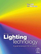
Figure 6.8 shows an elliptical reflector in its most common application in a profile projector. With the source placed at F1 the reflected light is directed to F2. This reflector system is comparatively efficient compared with the true radius reflector but it still suffers the losses shown. It is pointless making the reflector larger to collect more light if the resultant increase in collection cannot be directed onto the first lens at an angle that can be redirected by the lens. Some designers have used an annular reflector to redirect the wasted light back through the gate, however the steep angle of collection and redirection normally provides only 15% more efficiency at a much higher cost. A much better refinement is to use condenser lenses placed between the gate and the light source, this has the effect of directing the diverging rays of light through the gate and is normally a standard high temperature plano-convex lens. The first design requirement must be the light output angles. Once these have been fixed, the correct lens combinations can be determined and their relative positions drawn in. The gate diameter can now be positioned and the light ray lines drawn from the lenses to the reflector. Having satisfied these design requirements, any size of elliptical reflector can be used, with the choice varying from a long thin shape to one that appears to be almost a circle. They will all obey the same reflective law. This can be easily demonstrated with a piece of string and two drawing pins where the pins will be FI and F2 and the string will represent the light ray. This form of design provides a wonderful range of ellipsoidal sizes to be considered but would no doubt cause great hilarity in the tool room where the finished reflector tool is made. We would therefore recommend the method of construction shown in Figure 6.9.

Figure 6.7 (a) Circular reflector; (b) Waste light; (c) Fresnel lens system
The parabolic reflector is normally used as the name implies, in applications where a near parallel beam of light is required. The searchlight is a good example where the discharge source is mounted along the optical centre line facing the reflector. In this way a very efficient collection is achieved because all the light from the source is reflected in the output beam.
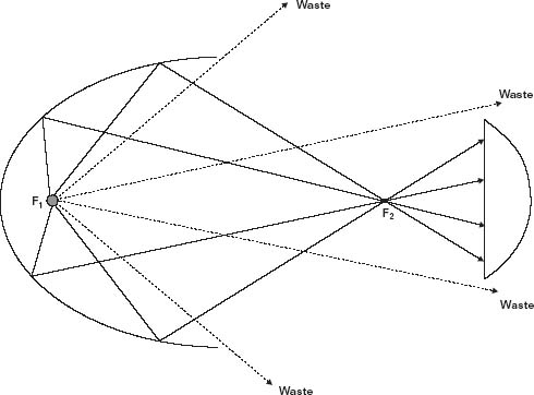
Figure 6.8 Elliptical reflector

Figure 6.9 Construction of an ellipse
Figure 6.10 shows a typical design for a beam light where the forward light from the source is redirected back through the source by a true radius reflector which can be part of the lamp's envelope which has been silvered or a separate reflector mounted in front of the source. Greater efficiency can be gained by the use of low voltage lamps that provide higher lumens per watt and a small source size, typically 12/24/48 V lamps are used. The only problem is, of course, that the mains electricity must be reduced by some form of either transformer or power supply circuit.
The type of open faced luminaire shown in Figure 6.11, achieves a degree of focusing by moving the source along the optical centre line of the reflector. The direct light from the source will not change, but the reflected light can be superimposed onto the centre of the distribution, producing a higher lighting level. This reflector design is arrived at by tracing the required rays back to the reflector where a tangent can be drawn between the angle from the source and the required ray. In this way a series of tangents can be formed into an approximation of the required curve. A good example of this type of reflector is the ‘Redhead’.

Figure 6.10 Parabolic reflector used in a beam light

Figure 6.11 Focusing open-faced reflector
The softlight reflector shown in Figure 6.12 is constructed in the same manner as the open-faced reflector by ray tracing. However if the light output is to render a soft shadow the small source must be covered up so that it does not produce a conflicting shadow which would appear as a well defined hard shadow from the source, followed by a secondary soft shadow from the larger reflector. As the softness of shadow is a direct function of the size of the reflector and the distance of the luminaire from the subject, it is desirable to have the largest reflector surface area that can be achieved. Additionally, a light stippling of the reflector will help to diffuse the light. Sometimes matt white paint is used, however, this deteriorates with age and becomes yellow, resulting in a reduction in the colour temperature. The reflector placed in front of the source is normally a true radius reflector so that the light rays from it can be ignored because they will be incorporated with the other rays produced by the source.

Figure 6.12 Softlight reflector
Figure 6.13 Cyclorama light reflector
The cyclorama reflector shown in Figure 6.13 is made by ray tracing in the same manner as the open faced reflector, but in this case an asymmetric distribution is required to provide as much light as possible to the top of the cyclorama. It is quite common with this design to make the bottom of the reflector a true radius drawn around to the point of cut off at the bottom of the cyclorama. In this way, the only light falling on the bottom of the cyclorama is the direct light from the source. The amount of reflected light is increased as the distribution extends up the cyclorama in an attempt to cancel out the fall off of the light through the inverse square law. It is not however practical to achieve a constant lux reading up the cyclorama because the light level at the bottom of the cyc will always be determined by the direct light from the source leaving insufficient reflected light available to match it, so the next best type of distribution is one that falls off evenly at a constant rate without dark or light bands which would draw attention to the change.
When lighting a large cyclorama from the top only; if an even distribution is required in the vertical plane, the cyc lights will need to be mounted 3 m or more from the cyc cloth and level with its top. A more common method is to use top and bottom mounted cyc lights to achieve this even distribution on the cloth. The reflector design is the same in principle for both top and bottom cyc units; a top unit is basically a ‘bottom’ unit turned upside down to achieve an asymmetric light distribution.
6.4 Luminaire types
The entertainment lighting industry should have its own dictionary of names and descriptions to guide the potential user through their catalogues. Every manufacturer has attributed to the proliferation of pet names for their products, so what is basically the same luminaire can have many names. Originally, no doubt, it was fun to build up a vocabulary that could only be understood by the lighting fraternity, thus adding mystique to the art.
The list is endless and not one of the names describes the use of the luminaire and each manufacturer uses a different name for a similar type. To expose the mystique we will place every luminaire in the entertainment business into only 11 groups, each group can be subdivided when reading a lighting catalogue into Wattage, Voltage, Beam Angle, Incandescent or Discharge Source, Manual or Pole Operated Controls followed by the finer points which separate one make from another. The 11 basic types are:
- Fresnel
- PC
- Profile
- Follow spots
- Floodlight
- Softlight
- Focusing reflector light
- Beam light
- Sealed beam and PAR lights
- Cyclorama/Backing light
- Effects
We will now break down the 11 groups, describing their use and optical systems.
1 Fresnel This luminaire employs a Fresnel lens and circular reflector with the source placed at the centre of radius of the reflector (Figure 6.14). To focus the light the source and reflector are moved together. The spot position of focus is when the source is at the focal point of the lens and maximum flood is achieved when the source is nearest to the lens. The variable beam is typically 8°–60° and provides a soft edge keylight used as the main illumination on the artist or subject in TV, film and photography and for large area illumination in theatre. One disturbing fault with the Fresnel is that light is scattered from the top of the risers on each zone of the lens which can cause a problem of spill light.
2 Plano-convex The PC uses a plano-convex lens and circular reflector and is similar to the Fresnel in construction and performance (Figure 6.15). It is used mainly in theatre and has a beam appearance of an out of focus profile. In performing a similar role to the Fresnel the question is often asked ‘Why do we require both types?’ The main reason is that it has a well defined soft edge to the beam and does not produce spill light that would otherwise fall onto parts of the set or backing and cause problems. The disadvantages however are that the filament tends to image itself in full spot and any plano-convex lens has the problem of producing a dark hole in the centre of the beam between the full flood and the full spot positions. Some manufacturers provide a diffusion on the rear surface of the lens to reduce both problems.
3 Profile (Ellipsoidal USA) Europeans refer to this luminaire (Figure 6.16) as a profile describing its ability to project an outline of a cut-out image placed in the gate; whereas in the USA it is referred to as an ‘ellipsoidal’ which describes the type of reflector employed. The unit uses one or more plano-convex lenses and an ellipsoidal reflector, with the option of having condenser lenses to improve the light output. The light source is positioned at the first point of focus of the reflector. The beam size and focus of a zoom type can be varied by moving the inter-relationship of the two lenses and the beam can be modified to provide a hot centre or an even field by fore and aft movement of the source in the reflector. Normally the most rear position of the source in the reflector provides the most even beam and produces the sharpest images of the gate, shutter blades and gobos. To obtain an efficient zoom, the beam angles are normally restricted to 2:1, i.e. 16° to 32° or thereabouts. One luminaire can be designed to cover all of the beam angles but it would be very inefficient in terms of light output and would be as long as the narrowest beam luminaire and as wide as the largest lens – thus very heavy – instead of a thoroughbred a ‘luminaire camel’. On wide angle, the edge of the beam is often ringed in a halo of blue halation which can be removed by placing a reducing cut-out circle between the lenses at the expense of the luminance efficiency. Typical beam angles are 5° to 45°. The beam shape can be modified by four beam shaping shutters or an iris diaphragm which can be focused from a sharp definition to a soft edge. This luminaire is the workhorse of the theatre used mainly as a keylight for the artist, or as a silhouette projector. For TV and photography it is used as a gobo projector for backgrounds. The beam is a clear cut, well defined illumination that can be focused to provide a sharp image or the focus can be backed off to provide a soft edge without emitting spill light. The main disadvantage is that the housing is fairly long, particularly on narrow angle units and can prove a problem in restricted rigging space. In the past profile luminaires mainly used 1 kW and 2 kW lamps but in the past few years compact filament 575 W tungsten lamps have been used to give a high light output. Profile spots have now been developed using 150 W metal halide lamps with a 9000 hour lamp life. A light output of 612 lux can be achieved with an 18° beam angle at 10 m, with the advantage that all objects placed in the gate will remain relatively cool.

Figure 6.14 (a) Discharge; (b) Tungsten (courtesy DeSisti (UK) Ltd)

Figure 6.15 PC luminaire optics
4 Follow spots The optics for the follow spot are the same as the profile projector and the unit only varies from the above by the following characteristics. The gate area is much more elaborate than the profile, it omits the four beam shaping shutters and replaces them by two horizontal blades; one in the top of the gate and one underneath the gate. A single lever operates both blades in unison producing a variable parallel slot of light known as ‘Chinese’. The blades can close the gate completely, giving a blackout known as a ‘dowser’. In addition to the iris diaphragm for spot size and gobo projection, a dimmer iris is often provided by placing it in the light path but keeping it well out of focus. This has the effect of dimming the light without changing the colour temperature or the shape of the spot – a desirable feature for normal control and very useful when balancing the light on stage from two spots at different distances. A cruder, simple way of achieving this effect in profiles, as well as follow spots, is to put a barndoor from a Fresnel into the colour runners and move all four blades inwards to dim the output. Some follow spots provide a mechanical coupling between the two lenses to produce a zoom effect of automatically maintaining focus when changing distance. The main advantage of a follow spot is the ability to focus constant attention onto a moving artist, however, the disadvantage of a low angle follow spot without other illumination is a complete lack of modelling and atmosphere for anything other than the ‘sock it to them’ approach.

Figure 6.16 (a) Fixed profile; (b) Zoom profile (courtesy of ETC Europe)

Figure 6.17 Floodlight
5 Floodlight From Figure 6.17 it can be seen that the floodlight produces a very wide angle illumination which is unfortunately totally uncontrollable. The beam will not provide a cut off if a barndoor is used because of the large area of the source and reflected light, and therefore spills onto everything in front of it. It is hardly ever used in TV, except for house or working lights, and in the theatre it is limited in use to large areas of colour wash. Other disadvantages are the shadows cast from this type of luminaire give a confused rendering. The shadow from the filament is very hard in the vertical plane and softer in the horizontal if a linear lamp is used. Add to this the secondary shadow of the light from the reflector which appears softer than the shadow from the source and the resultant illumination is beyond control. The advantages are a very wide angle and high efficiency because most of the light is projected out of the housing. The units are usually low cost. The same principle of an open faced reflector is used in the portable ‘Redhead’, refined by moving the lamp to give spot and flood focusing. The disadvantages of poor barndoor control are tolerated in favour of the high light output, small size and weight.
6 Softlight The name Softlight refers to the shadow definition and implies that the edge of the shadow bleeds away without a defined edge to it. The ultimate softlight is the bounced light from the North sky which is so large in comparison to man that the light approaches from a very large angle so that we appear to have no shadow at all. There is therefore no such thing as a small softlight and the term is open to abuse. We do know, however, that the larger the reflector the softer the shadow so the design of a softlight is always a compromise between the largest that can be reasonably achieved and the size that can be tolerated. Softlights are mainly used in photography and TV as a fill light to lift the shadow areas created by the key light to an acceptable level for the film stock or TV camera. It is desirable to achieve this without creating more shadows on the subject. The main disadvantage is light spilling onto backings or cycloramas – this can be partly controlled by an egg crate louvre placed in the front of the luminaire which restricts the light output to an angle of 90° vertical, 120° horizontal. The term ‘soft’ and ‘hard’ are comparative and do not define the shadow created by the light. Charles Neenan tackled the problem by defining the shadow and produced a test whereby a cross is placed in front of a backing and the light is measured in the shadow area and the lit area. The two are expressed as a ratio, known as ‘the Neenan factor’. Whilst this method of test works, the industry has not adopted it, still preferring to put up a hand in front of a backing, and, after much consideration declaring the shadow to be good, bad or indifferent (see Figure 6.18).
7 Focusing reflector light There are many types and wattage of focusing reflector lights but the most famous is the ‘Redhead’. The name describes the colour of the housing, but of course the French have their own way of expressing themselves and call it a ‘Mandarin’ referring to its segmented shape. The unit is mainly used in TV and photography and is particularly useful in interview situations because of its comparatively high light output from a small unit and the ability to focus the beam. This focusing is achieved by moving the lamp fore and aft in the reflector which provides two superimposed beams, one from the direct output of the source, and the other from the reflector. When the lamp is moved into the spot position the reflector provides the increased intensity in the centre of the beam while the overall total light output angle remains practically the same because of the direct illumination from the filament. Two problems with all open-faced lights are hard shadows and the need to provide a safety glass or mesh to catch the quartz from the envelope in the event of the lamp shattering. The standards require that particles of quartz 3 mm or more in size are arrested.

Figure 6.18 Softlight illustration
8 Beam light This luminaire employs a parabolic reflector with the source placed at its centre of focus. With an ideal point source, the optical system would produce a parallel beam of light, the same diameter as that of the reflector. However, if a true radius reflector is placed in front of the source, it prevents the light from the source leaving the housing in a direct line, thus reflecting all the light that falls onto it back to the source and hence through the filament to the parabolic reflector. In real life, the size of the source has the effect of slightly spreading the beam and typical beam angles are 4° to 8°. A slight amount of focus can be achieved by moving the source fore and aft in the reflector and this will provide a few degrees change in the beam. This optical system has been used for many years in lighthouses and searchlights where in the old type of searchlight, a positive carbon was mounted along the centre axis of the reflector with its light emitting crater facing the reflector. The beam light was originally used by necessity in large opera houses and the big ‘Germanic type’ theatres, because of its high efficiency and narrow beam required when lights were positioned a long distance from the stage.
The main disadvantages of a beam light are that the beam angle cannot be increased to any great extent by focusing and that the most efficient luminaires will use a low voltage lamp to make use of its small source size and high light output (lumens per Watt) therefore requiring a transformer in the mains supply line. The main advantages are a very narrow beam for long throw applications, a high efficiency and very little spill light.

Figure 6.19 Sealed beam optics
9 Sealed beam and PAR lights A sealed beam lamp (Figure 6.19) employs the same optics as the beam light but replaces the front reflector with a moulded lens which has the effect of controlling the beam to a predetermined angle. Because the lamp is completely sealed, it can be run at a high pressure and consequently provides a high efficiency. The lamp manufacturers offer a choice of five beam angles by lamp selection, each lamp has a different lens moulded onto the front in quite the same manner as the car headlamp. The most popular lamp in entertainment is the PAR 64 and as with all PAR lamps, the number is the diameter expressed in 1/8 of an inch, therefore a PAR 64 is eight inches in diameter or 204 mm. The beam is usually oval and typical beam angles are (9°H12°W) (10°H14°W) (11° H24°W) (21°H57°W) (70°H70°W) for 240 V lamps. Beam angles and efficiency vary with voltage, particularly when comparing 240 V lamps with 120 V versions because of the small filament in the low voltage lamps. The most common application of this lamp is the Parcan generally used on ‘pop’ rigs for its high light output, small size, low cost and light weight. It is the only luminaire that comes to mind that costs less than the lamp that is used in it. Alternatively, manufacturers make a lamp with a plain glass front for use with a selection of separate lenses. Luminaires with parabolic reflectors and separate lamps are also manufactured, employing discharge sources and compact filament tungsten sources (see Figure 6.20).
10 Cyclorama/Backing light From Figure 6.13 it can be seen that the lower part of the reflector is a true radius about the source. This has the effect of returning all of the light that falls onto it back to the filament and through the envelope to the main part of the reflector. The main part of the reflector is designed to direct as much light as it can towards the top of the distribution and to only light the bottom part of the cyclorama with direct light from the filament. With the inverse square law working against the designer, it is always a problem to get enough light to the top of the cyclorama, so it is realised that a cyclorama or backing cannot be evenly lit from the top or bottom only when the units are placed relatively close (i.e. 1 m). It is necessary to light from both positions if an even effect is required. If only top or bottom lighting is used, then the fall off of the light should be designed to be a continuous reduction without any dark or bright bars. In this way, the change is not exaggerated.

Figure 6.20 (a) Discharge PAR features (courtesy of DeSisti (UK) Ltd) (b) PAR luminaire (courtesy of Electronic Theatre Controls (Europe))
The choice of linear tungsten halogen lamps is important because of the ring supports that hold the filament in the centre of the envelope. These cause shadows which will appear as five or six fanned out dark bars, projecting up the cyc, and can be overcome with the use of frosted lamps. When assessing the light distribution of cyclorama lights, it is not possible to get a true result by observing only one unit, because the lights are designed to have a wide horizontal angle of distribution, typically 45° each side of centre. It is necessary to use at least three units spaced at the recommended distance from the cyclorama and positioned at the correct distance apart; this being when the overlapping lighting gives an even horizontal coverage. Under these conditions it is possible to assess the vertical distribution on either side of the centre unit. Polar figures are not normally produced for cyc lights because they have no practical application, so it is normal for manufacturers to set up three lights as described above, and take readings progressively up the cyclorama and to show this information graphically. When setting cyc lights, it is a good guide to remember that it is the horizontal distance of the units from the cyclorama that determines the coverage, a small change in the horizontal distance will create a large change in light level opposite the luminaire and almost no change in the light level at the furthest point on the cyc because the length of throw in the vertical direction has hardly changed.
It is normal to place the groundrow 1 m from the cyc and have each recurring colour at 1.2 m centres (Figure 6.21). Top cyc units are rigged approximately 3 m away from the cyc at 2.5 m centres (see Figure 6.22).

Figure 6.21 Groundrow

Figure 6.22 Top cyc lights
Cyclorama lights are made in the following configurations:
- Single, double and triple units,
- four lights in line with hinges between each compartment for bending around corners, and
- four-way unit mounted in domino formation.
All types of units allow for up to four colours before the first colour is repeated to provide colour mixing or four particular choices of colour, but don't forget to include a clear compartment if you are using a red/green/blue colour mix to desaturate the colours. Also remember that the dimmer setting is just as important as the colour that has been chosen.
The design of colour frame can have ‘tiger teeth’ along the edge to break up the shadows created by the linear lamp filament being in line with the inside edge of the colour frame. This can be important in TV when lighting the cyclorama from the top and allowing it to spill out onto the floor. The main disadvantages of cyclorama lighting systems is that they eat up dimmer circuits at an alarming rate, so it is necessary to investigate distribution systems that can be patched from acting area lights to the cyclorama when required, and the possibility of using a 9-way plug and socket system at 4 × 5 kW per circuit, the cyc lights can then be daisy-chained to work in parallel. The space taken by the luminaire is always difficult to find in operation, and the TV lighting barrel system presents a particular problem of trying to rig the lights on the side of the cyclorama that is presented with the ends of the barrels without tying up every barrel for this purpose – a point often overlooked when designing a studio lighting barrel system.
11 Effects light Effects projectors normally employ a true radius reflector or an elliptical design similar to the reflector used in a profile projector. Figure 6.23 shows an elliptical reflector with its increased efficiency when compared with a true radius type. The first element is normally a heat absorbing glass that has the effect of reducing the heat passing through it by about 80%, with a light loss of approximately 20%. This special glass requires an airflow over its surface to dissipate the heat collected. An alternative heat filter is a glass with a dichroic coating which reflects the heat from the surface of the coating back into the luminaire. This type of filter is slightly more efficient than heat absorbing glass but care must be taken to ensure that the source is not overheated.

Figure 6.23 Effects optics
The condenser lens as the name implies helps to direct diverging rays of light through the gate and can be a conventional plano-convex lens or to provide a slightly diffused output and a weight saving, a Fresnel lens is often employed. The gate is designed to accept a conventional photographic slide or a large piece of glass with the scene to be projected painted onto it. It is therefore possible to make a photographic slide of the actual backing required from the correct position to give the correct perspective and then project it onto a white backing. In the same way, an effects projector can be used to project a scene onto a backing for the scenic artist to sketch in the outline with the correct perspective before painting it. An alternative accessory is a rotating disk positioned on the front of the projector with the appropriate effect painted onto the rotating glass i.e. rain, fire, snow, etc. In this way a moving effect can be created at variable speed. A choice of objective lenses is made available to give the coverage required at the appropriate distance. Disadvantages are the high cost of the projectors and high effects costs, comparatively low light output levels that cannot compete with high lighting levels on the TV and film set. A very steady mount is required, as any vibration will produce judder in the output beam and ruin the effect.
A modern development is an effects system which uses a small motor driven drop-in unit for the gate of modern low wattage luminaires. The unit consists of a motor driven roller and a take-up roller with a continuous belt of stainless steel or polyester with etched patterns. There are a large selection of off-the-shelf designs and it is also possible to create your own effects and these can be manufactured in either stainless steel or polyester loops. The units can be controlled via the mains or driven from DMX control systems.
6.5 Special designs
Multi-purpose luminaire
This is basically a focusing Fresnel mounted back to back with a Softlight and was developed for TV in 1961 (see Figure 6.24).
The reason for the development was a requirement to mount luminaires at regular intervals all over the studio at approximately 2 m centres, known as a saturated lighting system, where in this way a light can be found somewhere near the required place, pulled along its barrel and positioned. The luminaire is then rotated, offering the choice of Fresnel key light or Softlight. A switch is then selected to divert the electrical supply to the chosen light, and a second switch selected to provide a choice of power. This is achieved by using 4 tungsten halogen linear lamps in the soft end, and a twin filament, 4 pin lamp in the Fresnel end.
This arrangement is intended to cover 80% of the requirements of the LD, with the remainder being mounted for each show. The additions include 1 kW Fresnels, profiles or specials as required. To add more flexibility to the system, the multi-purpose luminaires are mounted onto pantographs to provide a degree of independent height adjustment. The BBC adopted this form of luminaire in all their major studios, claiming very fast turn round time, increasing the output from the studio. Leaving the lights permanently rigged, substantially reduced the damage normally caused when lights are continuously rigged and de-rigged.
6.6 Fluorescent lighting
Fluorescent light sources have been used in TV over quite a number of years but generally in situations where they were used more for effect rather than for their intrinsic lighting values. In more recent times, with the advent of smaller fluorescent tubes and high frequency operation, it has been possible to design luminaires not too large in physical size for use in studios and on location. The claimed benefit of using fluorescent light sources is that they are much more efficient than tungsten with three to four times the efficacy (lumens per Watt). Although they have a high efficacy they do not lend themselves as a focusing source, and for example they have an efficiency (usable light divided by total light output) of around 40% which is comparable to the 49% of an open faced luminaire in flood and the fluorescent luminaires only gain by the tubes producing more visible light and less infrared than the equivalent tungsten source and therefore, per watt, have a light output which is about twice that of tungsten. The fluorescent luminaires tend to be a cooler source of light and they produce less glare to the artiste.

Figure 6.24 Dual source (a) Softlight; (b) Keylight
Fluorescent units designed for TV usually operate on frequencies between 28 kHz and 42 kHz giving an improved efficacy of output and virtually flicker free light. Modern phosphors allow for colour rendering indices of better than 70 and can be as high as 90 but this usually means a reduction in the efficacy of the fluorescent tube.
The fluorescent lamps selected for this type of lighting have the normal phosphor coating inside the tube together with a coating of various rare-earth high output phosphors, similar to those used for the production of TV colour cathode ray tubes, and are called tri-phosphor tubes. By varying the combination of the red, green and blue phosphors, different shades of white can be produced and these lamps are referred to as tri-phosphor lamps. This type of lamp can provide high light output with good colour rendering with a reduction of around 7–10% in input power compared with more conventional phosphor coated fluorescents.
Early applications for fluorescent lighting in TV were broad sources such as fill lights and for back lighting large diffuse panels used for Chroma Key. One special use was in the design of fittings used over snooker tables for tournaments which required a soft source which was also cool. The main use of fluorescent lighting is usually in News and Current Affairs studios where the set-ups are fairly static and it is reasonably easy to control the light.
Table 6.1 Light output comparison (at 3 m)
Luminaire type |
Power rating (W) |
Mode |
Beam width |
Light output (lux) |
Vid-lite (fluorescent) |
375 |
n/a |
60° |
830 |
Quasar (fluorescent) |
416 |
n/a |
76° |
700 |
Mizar (tungsten) |
500 |
Flood |
46° |
900 |
Pulsar (tungsten) |
650 |
Flood |
72° |
920 |
Redhead (tungsten) |
800 |
Flood |
86° |
720 |
Piccolo (discharge) |
200 |
Flood |
48° |
1150 |
Piccolo (discharge) |
575 |
Flood |
46° |
2000 |
Note: Manufacturers’ published figures.
Although there are small News areas that exclusively use fluorescent lighting, generally because of the comfort level due to the low heat produced, the general application of fluorescent lighting would appear to be in hybrid type studios where the keylights are small tungsten Fresnel sources, with the fill light produced by fluorescent sources. The overall aim is to keep the heat level in the area fairly low.
To obtain higher light levels from fluorescent fittings it is possible to fit intensifiers which are essentially reflectors fitted to the front, which instead of letting the light spill to the sides and top and bottom, reflects it back in the general direction of the main beam. As with all light sources, the introduction of louvres or controlled screens, invariably reduce the light by a small amount. Dimming of fluorescent units can be accomplished by a manual control using a potentiometer, a standard 0–10 V analogue control signal or DMX digital control signal.
One of the problems with fluorescent lighting for TV is that it is not focused light but tends to be a broad source of illumination and therefore only controlled by the use of louvres (control screens). Although the louvres can reduce the amount of light emanating from the side of the beam, the sources are very wide angle in application, thus their adoption into normal production TV studios would probably not be advantageous because of their physical size and control of light. Fluorescent fittings can now produce outputs of around 600 lux at a distance of 3 m from the subject with unit dimensions of 500 x 400 mm and in excess of 900 lux at 3 m from units approximately 700 mm across by 700 m high (Table 6.1). Although generally the lighting is acceptable for fairly static newsreaders, the lack of pronounced modelling does reduce the three dimensional effect on camera. The small amount of heat generated by fluorescent lighting means that these fittings are advantageous in situations where ventilation is poor.
Fluorescent luminaires for TV, film and photography, particularly digital imaging photography, come in power sizes from around 100 W to about 1000 W.
6.7 Battery hand lamps
These are mainly used for news gathering on outside locations, so they are completely self powered from their own battery. The most popular batteries for size to weight ratio are nickel-cadmium. A typical luminaire has an open-faced reflector, containing a tungsten halogen or discharge lamp. The largest tungsten halogen lamp is 250 W at 30 V and the range of daylight discharge lamps include 125 W, 200 W, 275 Wand 400 W. The battery unit will also be complete with a high frequency converter for the discharge lamp. A degree of focusing is obtained by moving the lamp in the reflector.
General care of Ni-cad batteries
Ni-cad batteries retain their capacity better if the discharge cycle is completed to the point where the knee of the discharge curve is reached. To discharge batteries beyond this point may push some cells into deep discharge from which they may not recover, thus potentially rendering the battery useless. Overcharging a battery is not good practice and if a battery has been left charged for some time or is partially discharged, it should not be recharged before it is discharged fully.
Charging batteries
A typical charger of the fast type will charge a fully discharged 7 Ah battery in approximately 2 hours, or a 4 Ah battery in approximately one hour and then drop to a trickle charge state.
There is no common connector standard for many of the proprietary battery packs and belts used in the lighting industry; therefore, it is important to have the necessary adapter leads for the various items of equipment.
6.8 Assessment of luminaires
The LDs assessment of a luminaire is how well can he achieve his lighting requirements with this instrument, which is quite understandable from his point of view. The electrician that has to rig and set it has quite different criteria and the maintenance engineer has his own particular problems to keep it in good repair. The LDs assessment is quite straightforward and can be seen by demonstration, it is also well documented by the lighting manufacturer with polar figures for the light output.
We shall therefore turn our attention to the mechanical assessment that will affect the reliability and practical needs of the user. It is most interesting to watch the experienced practical user at any exhibition. He will walk up to a luminaire and in minutes run through a set routine of things to try, gained by years of disappointment and annoyance with things that can go wrong and just don't work in the way that they should. His checklist leaves the manufacturer in no doubt that he is demonstrating his product to a discerning user.
Luminaire checklist
Pan and tilt
Unlock the tilt lock knob and see if the unit is in the centre of gravity. Not only does the luminaire take charge and trap your fingers, if it is not in balance, but it will also put a pressure on the locking mechanism that can result in the luminaire drooping after it has been set; so the second test is to lock the tilt mechanism and try to force the luminaire downwards, making it slip in the yoke. If the unit is pole operated, try the tilt and pan for backplay in the drive mechanism. In the case of the tilt, an out of balance luminaire will result in a jerky movement in one direction and a heavy load in the opposite direction; this is caused by the load alternately taking charge and then being arrested by the gears. Backplay in the pan movement will result in a horizontal wandering movement after the light has been set. Check that the carcass rotates in the yoke assembly correctly, particularly with open barndoors. When pan and tilt pole operation is fitted, ensure that they can be over-ridden by manual adjustments.
Focus
Here we are looking for a smooth movement, best tested with the luminaire pointing 45° down from the horizontal. This will show up judder, if it exists, or sticking, followed by a sudden movement, both of which cause lamp failure due to the fact that the lamp must be lit to focus it when the vibration on the hot filament can cause it to rupture. Check for ‘end stops’ on lamp holder movement within the luminaire body.
Shutter blades
Profile shutters have always been a problem, mainly because they are in the hottest part of the beam and will normally run at a temperature that makes them glow red, so adequate insulation on the operating handle is essential. The most common complaint however, is the shutter blades that slide down in the guides when they get hot, so try it after the other tests have been done to make sure that you maintain a positive movement on the blade at high temperature (see Figure 6.25).
Profile edge focus
Most manufacturers demonstrate a profile projector in a sharp focus position, demonstrating its ability to project a well defined image. Adjust the lens movement to the minimum and maximum angles to determine if the edge is sharp over the whole range and at the same time observe the edge for colour fringing. It is most important with the profile that it can be soft focused, so determine there is sufficient lens movement at both ends of travel to achieve a soft edge.
Barndoors
The main points to observe are that the flaps stay put with sufficient friction to sustain the top flap when it is hot. A floppy barndoor flap is the lighting man's cross. Check that smooth rotation can be achieved by poking it with a pole (quite a common practice). Light leaks can be assessed by half closing the two small flaps and then bringing the large flaps in to touch them. A well defined ‘letter box’ shape should be produced at this point; observe any spill light that comes out of any slot between the sides of the short flap and the large flap. This is a good time to see if spill light comes out between the back of the barndoor and the front of the housing. One easy way to check for spill light is to pass your hand around the area of concern, which will soon pick up any unwanted light.

Figure 6.25 Shutter blades
Safety requirements
The following items should be checked. Has the luminaire had a drop test done, and if so, was a certificate issued. If so this should be provided. Luminaires are also generally supplied with safety bonds or chains and these should come with certificates or specifications indicating their suitability for use with the item of equipment. Have adequate safety precautions been taken against an exploding lamp and the loss of minute pieces of glass? Secondly, have precautions been taken with regard to lens breakage and the possibility of large pieces of glass leaving the luminaire. Ensure that the most important bolts and screws which attach items that may become dislodged from the luminaires are adequate for the purpose intended. Are supplementary safety bonds or clips provided for any detachable accessories, such as colour frames, barndoors, etc. or how are the barndoors retained in normal practice? Check for any sharp edges or dangerous protrusions which in practice may give problems for the operators.
Burning angle
It is a requirement to state the permitted burning angle of the luminaire. This is normally found on the product label and will give the permitted angles above and below the horizontal. This limitation can be imposed by either the luminaires’ cooling system or the lamp manufacturer.
Spares
Ask to see the spares list. Some manufacturers do not automatically provide one; this could save a lot of trouble identifying spare parts in the future. Check on the availability of spares and what components are used and where are they sourced.
Lamps
Determine if the type of lamp used is made by more than one manufacturer or if not, is it going to be readily available in your area. One common problem with lamps is arcing at the pins. Check the clamping arrangements for any lamps in use. In addition check for the ease of operation when fastening and unfastening lamps in their holders.
General
A general inspection should examine the ease of stacking for storage purposes. Where is the attached luminaire cable stored when not in use? Check for ease of handling when being carried and rigged.
6.9 Centre of gravity (C of G) considerations
Every luminaire is suspended by a yoke, stirrup or fork that will enable the luminaire to rotate (pan) and to tilt. It is the tilt movement that requires to be mounted at the C of G of the luminaire. Whilst every luminaire has a means of locking the tilt movement, or in the case of a pole operated unit, gears are provided to hold it steady in tilt, it is necessary to position the yoke at the C of G to prevent judder. In the case of pole operation, if the luminaire is out of balance it will be difficult to rotate the pole in one direction and judder will result in the other direction caused by the gears alternately releasing the load and stopping it again. In the case of the manually operated luminaire, an out of balance unit causes two main problems: one, when the tilt lock is released the out of balance weight takes charge and rotates the luminaire very quickly, normally trapping your fingers between the housing and the yoke. The annoyance caused by an out of balance luminaire is seen when rigging lights onto a bar which has already been fully rigged and all lights focused and set. Then an additional unit is added – the worst case being an out of balance profile. The influence of the weight of the large lenses mounted at some distance from the C of G produces a moment about the mounting hook clamp which tends to rotate the bar causing all of the other lights that have been previously set to tilt downwards, much to the annoyance of the electrician that has to reset them all. Having established the desirability of having luminaires in balance, sometimes a compromise is required because the C of G might come in line with the gate, shutters or some other obstruction.
6.10 Ventilation
The importance of adequate ventilation in a luminaire cannot be overstated. An overheated lamp will give a short life, the internal electrical system and lampholder will deteriorate and the housing will become dangerously hot. The rules to achieve good ventilation are simple but are so often ignored. A common mistake is to believe that lots of holes in the housing will introduce a lot of airflow through it. In fact, the opposite may be true. A splendid example is a kiln, where a chimney is erected with hot air rising through it, creating a partial vacuum behind it, sucking the air into the kiln at the place where it is required to fuel the fire. The same is true for luminaires and an air path is worked out bearing in mind the working angles of the unit to determine the inlet and outlet path. One system is to have an inlet – scoop or mouth – positioned so that internal baffles can direct the air across the base of the lamp and then between the lamp and reflector and ultimately through an escape chimney. The chimney has to be designed so that water or foreign objects cannot directly enter, electrical safety has to be checked by using ‘British Standard Finger’ tests.

Figure 6.26 Luminaire ventilation air path
This system works well to maintain the correct lamp temperature, however other means are required to cool the housing. If a wall cavity is provided by placing internal baffles in the housing, a separate ventilating system can be adopted to keep the outer skin cool. By providing separate inlet vent holes between the two skins, the air can be accelerated through the cavity by positioning the outlet slots adjacent to the chimney outlet, the hot air rising through the chimney creates an air rush around it, sucking the air up through the two skins. A third ventilating system will be required around the lens and colour filter (see Figure 6.26).
6.11 The carbon arc
Most high efficiency carbons produce about 46 lumens/W, which is roughly double the efficacy of a tungsten halogen lamp and half the efficacy of a discharge lamp. All of the light is emitted from the centre of the positive carbon, the positive is constructed by an outer shell made from compressed carbon with a core injected under high pressure made of various rare earths and carbon. This enables the manufacturer to create the correct mix for maximum efficiency and the required colour temperature. This construction also provides a hollow in the centre of the core which is containing the crater – that is the centre of the light output. It is necessary with most carbon arc luminaires to have an operator present to keep a constant distance between the two carbons and this is known as trimming the carbons.

Figure 6.27 Carbon burning characteristics
The correct burning position can be seen from Figure 6.27 where the tail flame is held in the vertical at the correct angle. If the positive or negative carbons are allowed to overfeed and become out of alignment, the tail flame will become unstable and create a flicker and ultimately the carbons will set up a squealing noise. One simple method of setting up a carbon arc when cold is to take a spent end of a positive carbon and use it as a gauge by placing it between the tip of the negative and the front edge of the positive carbon. In this way a reasonable running condition will result when the carbon is struck – that is the negative is raised up until it touches the positive and then allowed to drop immediately an arc is struck. As soon as the arc has been established the gap can be adjusted by eye through the coloured glass of the viewing port. The running speeds are normally adjusted by a motor drive which feeds the positive and negative carbons towards each other at a predetermined rate which can be varied by a potentiometer. The negative carbon does not rotate, however the positive carbon is rotated continuously to prevent the outer shell of the carbon burning away at the top and allowing the crater to spill out. Carbons always operate from a direct current which can be derived from generators or from a transformer rectifier unit working from a.c. mains.
If carbons are used in a confined space, adequate ventilation must be provided to extract the fumes and the large quantities of ozone which are produced. Arcs normally work with a controlling ballast in series with the supply to them, the ballast will provide high voltage to initiate the arc and then become self regulating as the arc starts to draw current through the ballast increasing its resistance and reducing the voltage. Arcs have mainly been replaced by the higher efficiency discharge sources which do not require adjustment during operation and can therefore be remote controlled. However, the arc still lives on and is still used in some rental departments throughout the world, due to the dramatic quality of light and by those practitioners who tend to use them for nostalgic reasons.