5
Light sources
Light can be produced from electricity in several ways and the most important are:
- Incandescence Light and infrared energy are produced by raising the temperature of a substance (e.g. tungsten) until it is incandescent.
- Electrical discharge Light is produced by electricity passing through a gas or vapour, agitating or exciting the atoms of the filling to produce light, UV energy and infrared energy.
- Fluorescence and phosphorescence The process by which UV energy is converted into visible light by phosphors.
Source |
Lumens per watt |
100W household lamp |
13 |
3200 K tungsten halogen lamp |
26 |
HF fluorescent lamp |
80 |
HID lamp 6000 K |
95 |
Table 5.1 Output as a percentage of input power
3200 K Incandescent lamp |
|
Losses |
12% |
Infrared |
77.5% |
Ultraviolet |
0.5% |
Visible light |
10% |
Fluorescent lamp (HF operation) |
|
Losses |
28.5% |
Infrared |
0.5% |
Ultraviolet (for phosphor conversion) |
40% |
Visible light |
31% |
Metal Halide discharge lamps |
|
Losses |
18% |
Infrared |
34% |
Ultraviolet |
11% |
Visible light |
37% |
5.1 Incandescent sources
The original lamps were very expensive. From 1883 to 1900 the price was 25p while an engineer's salary was £1.50 per week, so in today's terms, 16% of an engineer's weekly salary would seem extortionate for a common household lamp. In 1840 Joseph Wilson Swan showed an experiment of burning a thin filament made of carbon in the open air. It lasted a few seconds and was the first of his experiments. The development of the incandescent filament lamp was long and tedious, Swan finally completed his design and was able to demonstrate it in Newcastle in 1879. At the same time Thomas Edison was working along the same lines in America and was astute enough to take out a British patent for a carbon filament burning in a vacuum. The following 4 years were largely taken up by a legal battle between Edison and Swan over the rights to the idea with the only winners being the Patent lawyers, for in 1883 they called off the fight and joined forces, registering the Edison and Swan United Electric Light Company. The manufacture of the carbon filament, which incidentally has the reverse characteristic to tungsten inasmuch as its resistance decreases as it heats, was manufactured until 1906 when the tungsten filament was first produced for domestic sales. This enabled the bulb manufacturers to greatly increase the light output from the filament by lacing it around supports and coiling it back upon itself to maintain a high temperature by the close proximity of the filament coils to each other. The filament could also run at comparatively high colour temperatures in view of the fact that the melting point of tungsten is 3410°C.
A common household 240 V 100 W bulb has 1147 mm of wire in the filament. Therefore the next development was the coiled coil filament where the wire is returned and coiled again on itself; this was a great advance in reducing the size of the source. Various improvements were introduced in the following years, one of which was the use of nitrogen and argon in the lamp to retard evaporation of the filament and thereby prolong its life.
The next significant development in lamps occurred during the late 1950s and when it became commercially available in 1960 was known as the Quartz Iodine lamp, later to be renamed Tungsten Halogen with its benefit of the tungsten halogen cycle. Other advances were made by including internal reflectors inside the envelope of the lamp and in some instances a dichroic coating which not only reflected the light forwards but permitted the infrared end of the spectrum to pass through the reflector, thereby reducing the heat in the beam.
Tungsten halogen lamps can be divided into two groups of manufacture – synthetic silica quartz and hard glass. In the case of the synthetic silica quartz, the walls are extremely strong and have a high melting point thus allowing a small envelope which permits a comparatively high internal pressure. This has the effect of doubling the life in comparison with hard glass. Therefore the hard glass envelope is thinner and much larger but still maintains the tungsten halogen cycle. At half the life one is not disappointed to find that it is approximately half the price, thus the cost per hour of life is approximately the same. Therefore the choice is purely a high initial capital investment with the synthetic silica quartz lamps with reduced maintenance replacements against the low initial cost of the hard glass.
The electric lamp is a heat generator from which we can get a little light. This would appear to be an odd statement until one compares the efficiency. The conversion of total electrical energy in a 3200 K lamp produces 10% light and 90% waste. The light energy is transmitted through the air which is also absorbing heat from the beam and the remainder of the heat is absorbed by the subject being illuminated – a very important fact when considering ventilation requirements for a building (see Figure 5.1).
The temperature of the lamp is one of the manufacturers’ main design considerations, with the need to operate at relatively high temperatures, bearing in mind the melting point of tungsten which is 3410°C. The high efficiency 3400 K (3127°C) lamps are obviously burning very near their melting point and therefore only give approximately 20 hours life. The lamp designer has to concern himself not only with the correct temperatures to keep the tungsten halogen cycle working, but also the filament design to achieve the exact colour temperatures required (Figure 5.2). He also has the problem of maintaining the lamp's seal temperature within the manufacturer's stated maximum. This is because the ‘lead out’ of the filament through the silicon quartz envelope is made by a thin foil of molybdenum. The expansion of molybdenum and quartz are not quite the same, therefore as the temperature increases the difference increases and at very high temperatures the seal between them would become porous and the molybdenum would oxidise.

Figure 5.1 Energy-wavelength curve of a 500W incandescent lamp
Typically, the maximum temperature of molybdenum seals fall into three categories:
- Long life lamps with a maximum temperature of 350°C,
- Short life lamps 400°C, and
- Special lamps designed to work with a maximum seal temperature of 500°C.
However, caution should be taken with the high temperature seal lamps because some of them have a shorter light centre length than the standard lamps and cannot be interchanged, because of misalignment within the optical system, however when used in a purpose designed luminaire, the higher seal temperature lamps permit the manufacturer to design much smaller lamp housings. When lamps are used in a design with inadequate ventilation, the end of life can be seal failure rather than filament failure. At the other end of the scale, if the source is force cooled by a fan, reducing its wall temperature to 250°C the tungsten halogen cycle is affected.
Filament vibration can sometimes cause an acoustic problem. With a sinusoidal voltage applied to the lamp, the current produces a shock on the filament every half cycle. The lamp manufacturers tried to reduce this effect by calculating the spacing of the supports and clamping the filament supports onto the filament using non-magnetic wires to try to dampen the vibration. With thyristor dimmers the situation is worse and this is because the current is rapidly switched on every half cycle and does not increase slowly as it would in a sinusoidal waveform. The worse position for vibration is at half power when the dimmer is firing at a 90° angle. Manufacturers of high quality dimmers use a choke in the output to dampen this effect. It is an interesting experiment to observe the filament movement with various firing angles by taking a standard lens and positioning it at its focal length from the filament projecting the image onto a screen, the filament can be focused and the movement observed.

Figure 5.2 Filament designations (courtesy of General Electric)


Figure 5.3 (a) A typical high wattage studio lamp; (b) A typical 4-pin twin filament studio lamp; (c) A typical low wattage theatre class tungsten halogen lamp; (d) End section of a typical quartz linear tungsten halogen lamp (courtesy of General Electric)
The cause of the inrush current on the initial switch on of a cold filament is that tungsten has a comparatively low resistance in its cold state. The current initially reaches a very high value but as soon as the filament heats, its resistance increases and the current soon falls. To generalise, the inrush current can be from 10 to 17 times the normal running current, depending on the filament size and the impedance of the circuit, but only lasts for approximately 0.2 to 0.8 seconds. This can become a problem in determining the type of fuse for a circuit and the current rating of miniature circuit breakers (see Dimmer section – circuit protection).
All lamps are designed for one specific voltage, the manufacturer decides the following criteria: operating voltage, colour temperature, life, current and the wattage which is a product of the current and voltage. The performance of a light source is tested in an integrating sphere, where the total luminous efficacy is measured and then expressed in the manufacturer's data as ‘lumens per watt’. The higher the lumens per watt, the higher the lamp temperature and consequently the colour temperature.
If any parameters are changed, all the other values must change because they are all interrelated. The easiest way to understand that is to take the case of varying the voltage to the lamp. If the voltage is reduced, the flow of current will reduce, and as the wattage is a function of volts × amps, the wattage will reduce. Because the filament is now burning at a lower temperature, the colour of the light will change and will move towards the red end of the spectrum and the good news is that the life will be extended.
It is apparent by now that it is very difficult to calculate the outcome of a voltage change because all of the values that could be used for a formula are variables with no constant to latch onto. Even the resistance of the filaments increases when it is heated, therefore, when we reduce the voltage and thus the heat of the filament, the resistance will decrease.
It is however, possible by the use of the graph in Figure 5.4 to read off all the changes that take place with varying voltage by starting with a complete set of known values. Fortunately, every lamp manufacturer provides the relevant information which is peculiar to his product so it is necessary to first determine the make and type number of the lamp. A typical example would be type: CP-40 (ANSI code FKJ) 240 V, 1000 W, 3200 K, 26 lumens/W, thus giving a total of 26 000 lumens and a life of 200 hours.
It will be seen that the horizontal scale of Figure 5.4 refers to percentage change of the applied voltage and the vertical scale shows the resultant change by percentage of the manufacturer's stated values.
Do remember to convert any value into a percentage of the manufacturer's stated value. For example, taking the CP-40 1000-W lamp quoted earlier, we have a rated voltage of 240. If the voltage is reduced, to say 205V, a reduction of 35 in 240 equals 14.6% (say 15%). Referring to the horizontal scale of the graph, percentage change of the applied voltage, a reduction of 15% gives a value of 85% voltage. Move vertically up the 85% line and read off the following values:
Light output |
60% of 26 000 lumens |
= 15 600 lumens |
Watts |
77% of 1000 W |
= 770 W |
Current (A) |
92% of 4.17 A |
= 3.84A |
Colour temperature |
94% of 3200 K |
= 3008 K |
Life (est.) |
300% of 200 hours |
= 600 hours |
In the case of life, it was necessary to project the life curve above the graph and estimate that it would meet the vertical line at approximately 300%. When the life value is changed considerably, it cannot be estimated with great accuracy, however the principle gives a good indication of the life that one would expect. The example quoted is in fact the result of running the lamp at position 7.5 on the lighting control console, if it has a square law fader characteristic (refer to Chapter 8).
The electrical supply system in the United Kingdom is normally very good. However, the supply authorities are very generous with themselves in allowing a maximum variation of + 10% and −6% about 400 V for three-phase supplies and +10% and −6% for 230 V supplies which represents 253 V to 216.2 V. Referring to the graph, 253 V equals 106% voltage for a 240 V lamp which would result in a life of 50%, so don't always blame the lamp manufacturer for poor life performance – it might not be his fault.

Figure 5.4 Characteristics of tungsten halogen lamps
As a matter of interest, the change to a stated value of 230 V for the mains supply (for European harmonisation) has not caused too many problems in practice as most systems in the United Kingdom still operate at about 240 V and therefore most lamps will be supplied as 240 V versions for the United Kingdom.
When a tungsten filament is burning at a comparatively high temperature, tungsten atoms leave the filament and normally attach themselves to the inside surface of the lamp envelope. This is most noticeable in the household bulb, which becomes quite black by the end of its life. Theatre and studio lamps, before tungsten halogen designs became available, had the same problem resulting in the reduction of both light and colour temperature throughout their life. The chemical principle of including a halogen gas in the lamp to reduce blackening was well known for many years before it became practical to produce a lamp to accommodate it.
The first lamps to appear on the market in the early 1960s used a quartz envelope and an iodine filling. This had the desired effect but unfortunately the iodine had a slight pink colour when hot and changed the colour of the light. The new development was called quartz iodine but in fact most of the halogen gases would work in the same way. Unfortunately, most of these gases radiate a colour when heated or were quite obnoxious towards the tungsten filament, eating it away before it reached old age. Some halogens would even attack the filament when it was on the shelf, resulting in a very short life instead of an extended one. In general, the more reactive the halide, the more effective is the halogen cycle. So in theory, fluorine, the most reactive, should be the best but it is so reactive that it even attacks the glass or quartz. Therefore iodine, bromine and chlorine are the only ones in use for halogen lamps. Over the next 5 years, the manufacturing techniques improved, enabling the lamp manufacturers to use bromine in place of iodine and a synthetic hard glass in place of pure quartz.
Although this was a great technological breakthrough because bromine did not add an obvious colour to the light, and the new material for the envelope was cheaper than pure quartz, it produced havoc with the lamp manufacturers’ marketing departments that had spent years promoting quartz iodine only to have the name changed because the product no longer used quartz or iodine. The safe way out was apparent, because all lamps would use a tungsten filament and a halogen gas filling, therefore the name tungsten halogen was adopted.
The tungsten halogen cycle is simple in principle. Tungsten atoms ‘boil off’ and leave the filament; as they cool below 1400°C they combine with the halogen atoms and circulate within the lamp envelope. If the temperature fell below 250°C they would separate. However, by moving the envelope closer to the filament, thus maintaining a higher temperature, the compound will not separate. So the tungsten and halogen atoms circulate, in a convection effect, until they find a temperature above 1400°C, (the filament) when the compound separates and deposits the tungsten atoms back onto the filament (Figure 5.5).
Thus, it implies that the life of the lamp is infinite but, in practice, there are minuscule variations of thickness in the filament and the tungsten atoms are redeposited unevenly. Eventually, therefore, weak areas develop on the filament and ultimately cause lamp failure.
It would appear that a problem might occur when a tungsten halogen lamp is dimmed to a very low level, due to the fact it becomes cooler. However, in practice the evaporation from the filament is substantially reduced and the small amount that does deposit on the envelope is removed when the lamp temperature is restored to full.
The advantages of tungsten halogen lamps are:
- An extended life by using halogens and higher filling pressures with quartz envelopes.
- A constant light output throughout life.
- A constant colour temperature throughout life.
- A smaller quartz envelope means that compact luminaires can be designed.
- Reduced maintenance costs in time spent replacing lamps.
- In general, a higher light output is achieved (higher lumens/watt).

Figure 5.5 Simplified mechanism of the tungsten halogen cycle
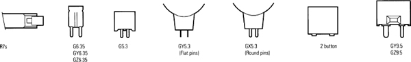


Figure 5.6 Some photographic lamps with their IED codes and normal names or common abbreviations. Note that the illustrations are not to scale (courtesy of General Electric)
One aspect of tungsten halogen sources that has to be considered is UV radiation. Synthetic quartz will pass UV rays and can cause a slight sunburn. For instance, if the skin is exposed continuously for 4–5 hours with a light level of 2000 lux, a slight reddening of the skin will take place with a 3200 K lamp. At half this level, 1000 lux, the time would be double. The problem applies particularly to lamps running in open reflector luminaires. If however, the lamps are operating behind a lens which is normally manufactured from borosilicate glass, the problem does not exist because borosilicate glass is a good UV filter.
Lamps for entertainment, in the main, have compact filaments to produce the smallest size source for the optical systems employed, with the exception of floods and softlights, where an elongated filament is a distinct advantage when trying to evenly illuminate a large reflector.
5.2 Discharge sources
If we accept that the sun was the first light source with a nuclear fusion reaction in its core, which is approximately 14 000 000 K and an outer surface temperature of 5800 K, then an electrical discharge was certainly the second.
Benjamin Franklin, the American statesman and scientist, who helped in the forming of the American Constitution, demonstrated how to electrocute oneself by flying a kite in a thunderstorm. That part of the experiment did not work, however, the real object of the experiment did. Franklin was so convinced that lightning was caused by an electrical discharge that he submitted himself to the risk of electrocution by pointing his finger at a metal ring attached to the end of a silk line that was holding the kite and demonstrated that a spark jumped from the metal ring to his finger. This experiment proved that light was generated from an electrical discharge and that Benjamin Franklin became the inventor of the lightning rod (which was a side product of the experiment).
We now know that the electrical discharge in the form of lightning is caused when the changing temperature within a cloud produces raindrops, hail and ice particles, which collide causing friction that produces a negative charge in the falling particles whilst the smaller rising particles within the cloud gain a positive charge. In this way, charges of up to 1 million volts can be produced in the clouds and cause sheet lightning if the discharge takes place between clouds, and fork lightning if the discharge is conducted to earth with a power estimated to be between 20000 and 40000A.
Sir Humphrey Davey (the inventor of the miners’ safety lamp), demonstrated an electrical arc between two rods of carbon in 1810. To maintain an arc the two rods were continuously adjusted at the same rate as they were being burnt away. A hot, dirty job, bearing in mind that carbon vaporises at 3382°C. These experiments employed Alessandro Volta's type of battery that used alternate plates of zinc and silver. This demonstration took place at the Royal Institution in London and required 2000 battery cells to provide the voltage and current required to maintain the arc. Battery operated carbon arc lights first appeared for entertainment when they were used at the Paris Opera. They were also used for floodlighting in the Place de la Concorde in 1830 and later at the Royal Exchange in London.
The early work by Humphrey Davey in his experiments with carbon arcs laid the ground for the film industry to develop a succession of arc lights from 1900 through to 1965. In the early 1900s the film industry blossomed in Hollywood and the studios all had their own generators to run the lighting. Because carbons arcs require a direct current (d.c.) to maintain an arc and a voltage in the range 40 V-85 V between the carbons, the generators were made to produce 115 V d.c. so that a resistance ballast could be conveniently connected in series with the supply to limit the current flow and maintain the arc volts.
The size of the luminaires were rated by the current that was drawn by the carbons, e.g. 40 A, 60 A, 150 A, 225 A and 300 A. For comparison, today's discharge lamps have a range which includes 125 W, 200 W, 270 W, 400 W, 575 W, 1.2 kW, 2.5 kW, 4kW, 6kW, 12 kW and 18 kW.
The ‘Brute’, an extremely powerful 225-A Fresnel spotlight, was developed in 1950 with geared drive to feed the carbons as they burnt away and to rotate the positive carbon at the same time. The ‘Brutes’, which were regarded with great affection, have today been replaced by discharge sources but comparisons are still being made between the old and the new. The light readings published by Mole Richardson (England) when they introduced the ‘Brute’ in 1953 make interesting reading:
At full flood, over a throw of 35 ft (10.67 m) the light level was 1000 foot-candles (10760 lux) with a beam width of 25 ft (7.62 m)
or
At full flood over the longer distance of 60 ft (18.29 m) the light level was 340 foot-candles (3661 lux) with a beam width of 43 ft (13.1 m).
The first practical discharge lamps were the cold cathode carbon dioxide ‘Moore’ tubes of 1895. Light is produced by the activity caused when fast moving electrons collide with molecules of gas. In order to accelerate electrons in the early lamps, the applied voltage was in the order of 2000–10 000 V at high frequency. Cold cathode tubes contain gas at low pressure, about 1/100 of an atmosphere. The colour of the light is dependent on the gases used. Carbon dioxide emits a very white light of very low intensity. Neon, first isolated in 1898, produces a red light and was used extensively in advertising displays from 1922.
The hot cathode lamp was a much better commercial proposition because it could operate at mains voltage. This was made possible by using metallic substances such as ‘thoriated tungsten’, which when heated to incandescence, produces a high level of electronic activity in the tube. By 1932 the hot cathode lamp led to the development of the high pressure sodium and mercury lamps with their much higher efficiency and these lamps are still in use in today's street lighting.
In all types of discharge lamps an arc is struck between two electrodes in an envelope containing an inert gas or vapour (Figure 5.7). A choke or electronic ballast is used in the a.c. supply to limit the flow of current after the arc has been established. Striking the arc is usually achieved by applying a high voltage across the electrodes to break down the resistance between them so that the gases or vapours inside the lamp may start conducting. Typical starting voltages are between 2000 V and 10000 V. At this point, the ballast takes over and regulates the flow of current. This starting up procedure normally takes from 1–2 minutes until the heat in the lamp vaporises the metallic elements which emit their characteristic colours, but if the lamp is switched off it will require to cool down before it can be restruck. The cooling time can take from 2–5 minutes to allow the internal pressure of the lamp to reduce to a level where conduction can occur. Alternatively, lamps are designed to be ‘hot restrike’ in which case a voltage between 20000 and 70000 is applied to overcome the high internal pressure and provide instantaneous starting when the lamp is hot. Discharge lamps are made using mercury, halides, rare earths and gases; often containing a mixture of many types of chemicals. There are some 40 metal halides to choose from and each manufacturer has his own ‘brew’. Iodides of sodium produce mainly yellow light, mercury emits blue/green light in the visible parts of the spectrum and a great quantity of invisible radiation in the UV wavelengths. Thallium is used because it emits mainly green light (see Figure 5.8).


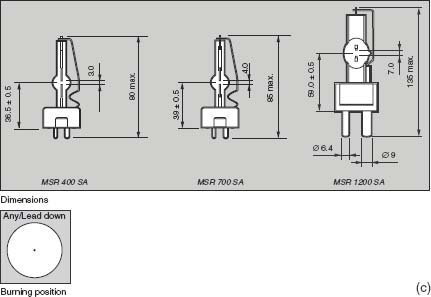

Figure 5.7 (a) MSI discharge lamps (courtesy Philips Lighting) (b) MSR discharge lamps; (c) MSR SA discharge lamps (courtesy Philips Lighting) (d) The axial and perpendicular polar light intensity distribution diagrams of a MEDIUM SOURCE lamp (courtesy Philips Lighting)

Figure 5.8 Spectral distribution of a discharge source
There are many types of discharge lamps, each with its own reference code, although many have similar characteristics (Table 5.2). We will only consider here the lamps that will be useful in entertainment, being those that approximate to daylight or have a correlated colour temperature approaching 3400 K. As the lamp manufacturing companies develop a new design of lamp, they register the reference as a trade name so other manufacturers are obliged to make up their reference for a similar development.
Although lamp manufacturers quote a colour temperature of the light in Kelvins this is only an approximation to the nearest point on the blackbody curve.
The total output from a lamp is made up of many separate colours from any number of the halides and gases employed to achieve the correct colour balance in the red, green and blue parts of the spectrum to match the response requirements for colour films and TV cameras.
Discharge lamps are generally made of a synthetic quartz material which permits very high operating pressures within the lamp when it is hot, therefore caution must be taken when relamping to ensure that the lamp has cooled down before the luminaire is opened. The operator must avoid handling the envelope even when the lamp is cool to prevent grease from the skin contaminating the quartz envelope. Care has to be taken when inserting a lamp into its holder because exerting pressure on the envelope can cause a fracture at its joint to the base.
The discharge lamp emits large quantities of radiation in the UV wavelengths which pass straight through the quartz envelope; it is therefore most dangerous to be directly exposed to the lamp. It must always be housed or have a lens or protective glass in front of it. It is fortunate that all standard borosilicate Fresnel lenses have the characteristic of absorbing UV but if the luminaire is open faced the safety glass provided must also be capable of absorbing the UV radiation. Because of the UV radiation, safety standards require that a switch is fitted to the lens door or safety glass to automatically extinguish the lamp to prevent hazards to the operators and artists by opening the luminaire while the lamp is on. Alternatively the lens door or glass must be securely fastened by fixing screws or bolts.
Sources require an a.c. supply |
|
HMI |
Hydrargyrum (Latin for mercury). Medium arc. Iodides |
|
95 lumens/W, 6000 K |
|
Made by Osram |
HMI/SE |
Single Ended version of the HMI |
|
95 lumens/W, 6000K |
|
Made by Osram |
MSR/HR |
Medium Source Rare earth, single ended |
|
95 lumens/W, 6000K |
|
Made by Philips |
CID |
Compact Iodide Daylight |
|
70–80 lumens/W, 5500 K |
|
Made by GE Lighting |
CSI |
Compact Source Iodide |
|
90 lumens/W, 4000 K |
|
Made by GE Lighting |
DAYMAX |
Mercury Halide source |
|
95 lumens/W, 5600K |
|
Made by ILC, USA |
BRITE ARC |
Mercury halide source |
|
95 lumens/W, 5600K |
|
Made by Sylvania, USA |
Sources are fed from d.c. supplies |
|
EMI |
Xenon |
|
40 lumens/W, 6000K |
|
Made by GE Lighting |
XBO |
Xenon |
|
40 lumens/W, 6000K |
|
Made by Osram |
The end of life of an incandescent lamp is very obvious, however this is not the case with a discharge lamp. Normally the end of life will be caused by the electrodes burning back during their life, creating a larger gap, the effect of this is a poor starting characteristic requiring many attempts to get the lamp to run continuously after the initial high voltage spark is applied. Therefore inconsistent starting is an indication of the end of life.
Discharge lamps provide a comparatively small light source. This is certainly welcomed by luminaire manufacturers enabling them to make efficient optical systems. Another bonus is that the total light output of a discharge lamp is comparatively constant throughout its life. However, many lamps suffer devitrification of the quartz during life which is not visible to the eye but has the effect when the lamp is running hot of diffusing the inside surface making the apparent source size that of its envelope. This is most noticeable in ellipsoidal spotlights and follow spots where the initial light output can be double that of the light performance halfway through the lamps life. The effect of the apparently enlarged source size due to devitrification does not significantly affect focusing Fresnels.
Most of the modern developments in daylight balanced lamps have an efficacy of about 95 lumens/W. It is useful at this point to make comparisons with the studio incandescent tungsten halogen lamp of 3200 K that has an efficacy of 26 lumens/W. This means that the discharge lamp has approximately four times the light output of the tungsten halogen lamp for the same wattage or, an alternative comparison is, that for the same light output the discharge lamp is running at 25% of the tungsten halogen ‘lamp watts’ – an important fact when considering the heating effect in the luminaire and the air conditioning installation in a studio.
We make the point of saying ‘lamp watts’ because the current drawn from the mains may be much higher than would be expected. This is because the current and voltage are not always in phase and can have a ‘power factor’ as low as 0.5 when a choke ballast is used.
A typical example is a 2.5 kW discharge lamp compared with a 2.5 kW incandescent lamp. From a 240 V supply, the tungsten halogen lamp would draw 10.42 A, in the case of a discharge lamp supplied from an inductive ballast with a power factor of 0.6, the current drawn from the supply is 17.36 A, (W = VIcos ϕ where cos ϕ is the cosine of the angle of lead or lag of the current). This is obviously an important consideration in supply requirements. The current apparently lost between the resistive load and the inductive load is known as the ‘wattless’ current. Manufacturers usually add components to the ballast circuit to improve the power factor so that it approaches ‘unity’.

Figure 5.9 Power curves
Light flicker is caused by the light following the mains frequency from zero to a maximum value and back down to zero again. This causes a flicker at twice mains frequency when the source is current regulated by a choke and a film camera set to certain shutter speeds or shutter angles will ‘see’ this fluctuation and produce reduced exposure frames at repetitive intervals. This effect will render conventional ballast equipment useless at high shutter speeds. However, the problems can be overcome by the use of an electronic square wave ballast. By using very fast switching times between the positive and negative half cycles the current ‘OFF’ period is very small compared with the current ‘ON’ period; consequently the light output appears to be constant, and the user does not have to worry about any synchronisation for the various shutter angles of film cameras and the time-bases of TV systems (Figure 5.9).
Gas discharge lamps generate light from an electrical discharge with a fixed characteristic voltage which may be 70 V for low wattage lamps rising to 225 V for high wattage lamps. The resistance of the lamp falls rapidly above this voltage to a very low value and any attempt to simply connect a lamp to the supply would result in an uncontrolled power output and the bulb would simply explode. The gas behaves as a resistor to the current but has a negative characteristic, therefore to prevent the current increasing to very high levels and possible destroying the lamp we must control the flow of current.
5.3 Control of discharge sources
With a.c. operated devices, there are three ways in which we can control the flow of current:
- a resistor,
- a capacitor, or
- an inductor.
The main disadvantage of using a resistor is the high losses (l2 R) which results in very low efficiency and the generation of a lot of heat. A capacitor has the lowest inherent losses but unfortunately the waveform produced can damage lamp electrodes. Thus, these disadvantages of the resistor and capacitor has led to the inductor being the most commonly used type of ballast for discharge sources.
These ballasts are composed of copper coils wound around an iron core, in order to limit the losses in the ballast and to ensure that the lamp current is stabilised for various conditions, it is important to have the correct combination of the sizes of wire used, the type of magnetic core and the air gap. Due to an inductance being used in circuit, the power factor (cos ϕ) of the system is very low and a typical value is 0.5. To conform to the requirements of the supply authorities means that the power factor has to be raised to certain minimum value. This is usually accomplished by placing a capacitor across the mains input in front of the ballast. The inductance is chosen to have the right level of reactance to be able to support the difference between the lamp voltage and supply voltage at the rated current.
A complication is the tendency of the higher wattage lamps to have high operating voltages, say 225 V, and therefore only a small difference from the normal single phase supply voltage. The answer to this is not simply to use a smaller choke to support the voltage difference because after ignition a cold lamp will run at a voltage of only 30 or 40 V. If a small choke were used the starting current would be very large and would damage the lamp. The result is that many ballast chokes of 4kW and above have a boost transformer connected to the input to ensure that the supply is always high enough above the lamp voltage. All this makes the choke very heavy and almost always fitted with wheels.
Electronic ballasts overcome the weight problems associated with conventional ballasts by using switching regulators to control the output current feeding the lamp circuit, thus avoiding the need for a current limiting choke. The switching regulators will be running at a set frequency in the range 20 kHz-50 kHz according to the manufacturer's circuit design.
The essential components of an electronic ballast are:
- A rectifier to convert the input supply to d.c.
- A reservoir capacitor to convert the raw d.c. to smooth d.c.
- A switching current regulator to limit the output current.
- A d.c. to a.c. converter circuit to produce the actual square wave.
Discharge lamps, in practice, vary slightly in their operating performance due to the manual manufacturing methods which are generally employed. Even from the same manufacturer there are slight variations in the arc voltage and if on the low side this means that the lamp output will be lower in wattage than the stated output. Some may, of course, have high voltage and this means that the power is above the stated value of the lamp, thus overheating the arc and causing short life in the lamp. The lamp voltage is also variable with age. Other than the variations of voltage from a manufactured batch, there are also reasonable voltage differences between similar lamps produced by various manufacturers. To get around this problem, it is preferable that the electronic flicker free ballast system can sense the volts and the current and automatically adjust one to the other to give ‘power control’ so that the wattage output of the lamp is kept consistent with the manufacturers’ stated values. The frequencies of the square waves used with flicker free ballasts are between 40 Hz and 400 Hz.
It is essential that the output of the switching regulator is filtered so that high frequency components between 25 kHz and 50 kHz are not superimposed on the square wave output.

Figure 5.10 Electronic ballast (power factor corrected)
One of the foremost electronic ballast suppliers, Power Gems of Manchester, England use a 100 Hz square wave output with a switching frequency for the current regulator of 25.6 kHz. The units they produce are equipped with active power factor correction circuits (see Figure 5.10) giving a power factor close to ‘unity’ and also have a microprocessor management system to give messages on a LCD display for system status and information on any fault condition. Typical fault conditions may be ‘over or under voltage’, ‘output over current’, ‘over temperature’, etc. In all these conditions the output will shut down, a message will be displayed and a fault code stored in the internal logging system.
Many of the electronic ballasts of today have various outputs which can be selected according to the mode required e.g. ‘flicker free’, ‘silent’ 50 Hz, ‘silent’ 60 Hz, etc. When used in the modes other than ‘flicker free’ the appropriate square wave output has the square edges of its waveform ‘rounded off’ by circuits in the ballast unit, so that it approximates to a sinusoidal waveform.
An advantage of the electronic ballast is that it is possible with the correct selection of the discharge lamp to obtain a degree of dimming. However, dimming can only be performed over a comparatively small range typically 50% of the light output before the arc becomes unstable. One major problem that can exist during dimming is a colour shift so it is wise therefore to do tests before relying on dimming a discharge lamp.
Ignition system
To enable a discharge lamp to ignite, high voltage peaks have to be applied to the lamp, and the peaks are proportional to the gas pressure in the lamp envelope. Thus there is a difference between the ignition of a cold lamp which is at relatively low pressure and of a hot lamp which is at high pressure. The ignition voltage will be generally at least 2000 V and anywhere up to 10 kV with cold lamps. Some special discharge lamps which have a higher filling pressure in the cold state require higher voltages. When the lamp is hot, the pressure has increased by at least 10 times and to re-ignite lamps when hot voltages of between 20 and 70 kV are required depending upon the type of lamp.
Figure 5.11 shows three types of igniters used with discharge sources. In order to keep the igniter unit to a small size requires that the components are small and consequently this means that to avoid abusing the circuit the starting time must remain for very short periods (0.5–3 seconds). There is also a requirement to limit the number of starts per minute and this is generally specified by the lamp manufacturer. On the other hand, the lamp requires a minimum period of energisation to ensure that it starts reliably and again these times are given by the lamp manufacturer. Control of the ignition period is usually accomplished by means of an electronic time switch placed in the power supply or the lamphead.

Figure 5.11 Three different types of igniter: (a) Parallel igniter; (b) Igniter on ballast tap; (c) Series igniter
Problems in practice
If a magnetic ballast is used to regulate the current to the lamp and the unit does not have a good power factor the only problem that ensues is that the voltage and current are out of phase to some degree but their waveforms are essentially sinusoidal in shape. If an electronic ballast is used with a poor power factor there will be a substantial distortion of the electrical supply waveform, due to the nature of the circuits employed. This distortion, caused by a high harmonic content can give problems with a generator. The generator may become confused as to what are the correct circuit volts, and the Automatic Voltage Regulator (AVR) will take corrective action, usually raising the voltage which results in the connected equipment being over-volted.
With a balanced load on each leg of a three-phase supply there is virtually no neutral current when using loads with a high power factor; but balanced loads with high harmonic content will produce very high neutral currents due to the addition of triplet harmonics (Figure 5.12). In practice this means that the neutral conductor has to be rated much higher than would normally be expected.

Figure 5.12 Triplet harmonics
In the case of both magnetic and electronic ballasts a poor power factor means that some energy is wasted, only the ‘in phase’ current and voltage components of the supply qualify as watts! The wattless component means that losses in the generator will be higher, thus to supply the useful and wasted electrical energy the generator will have to be larger than would appear at face value. Power factors of around 0.7 will mean that a generator needs to be about 30% higher in output. This reflects in the cost of generation and the overheating in the system will result in increased maintenance.
The lamp envelope surrounding the arc acts rather like a miniature sound chamber and its shape affects the acoustic output of the arc. Although not usually a problem when using magnetic ballasts with a sine wave output; a square wave presented to the electrodes can induce an audible noise in the arc as well as in the ballast. Additionally, if there is too much ripple on the square wave supply there can also be quite high frequency noise coming from the lamp. These high frequency components are often the cause of lamp instability.
A very important factor with regard to the operation of solid state ballast units is the ambient temperature in which they will operate so that the solid state devices within the units do not overheat and fail. It is possible to fan cool all the devices within the unit but this has to be carefully engineered as the units may be used in all types of conditions where there could be an ingress of either dust or water vapour. In the Arizona desert, just to make things worse, there is a high proportion of copper dust – which is a good recipe for a high voltage flash-over.
The noise from the fans and the electronics in the ballast unit, although very low can be troublesome when the units are close to the acting area. Whilst the noise in the ballast can be isolated by running it in a remote position, care should be taken when positioning luminaires to determine if any noise is being directed towards any microphones in use. The noise from the luminaires is more of a problem when using the smaller sources from 200 W to 1.2 kW. Above these wattages the lights are generally working further away and the problem becomes less.
Other types of interference can be present in an electronic ballast. The output from the ballast can produce:
(a) Voltage spikes which can be sent back down the supply line and hence onto the mains, which in turn can affect other electronic equipment connected to the same supply.
(b) Radio interference transmitted down the supply cable to the luminaire which is picked up by microphone cables in close proximity, causing audible hum on the sound output.
The introduction of the EMC Directive requires that these problems are reduced significantly by the manufacturers; probably by the addition of high quality filters in the ballast unit.
5.4 Xenon discharge lamp
The xenon discharge lamp is very similar in appearance to other discharge lamps and has the same type of quartz envelope that should not be handled without gloves, because if oil from the fingers is left on the envelope, it will cause devitrification of the quartz when it is heated and produce a grey mark on the envelope that will overheat and can cause the quartz to blister. If a lamp has been handled it should be cleaned with alcohol before it is used.
The lamp also requires a very high voltage of approximately 40000 V to restrike it when it is hot and it produces large quantities of UV radiation, but here the similarity with other discharge lamps ends. Xenon's have been used for many years in film projectors and follow spots with great success, mainly due to the following advantages:
(a) D.C. operation means that the arc does not flicker.
(b) The lamps have a very good daylight colour rendering 5600–6000 K correlated colour temperature, with a colour rendering index approaching 95.
(c) A small source size with all of the useful light concentrated at the point on the cathode known as the ‘cathode spot’ which is near to the negative electrode. This means that the source can be positioned very accurately in a mirror optical system to redirect most of the light to the first lens in the system.
(d) When the lamp is switched on there is instant constant light with no warm up time required. The lamps can be switched on and off without the problem of waiting for them to cool before being restruck.
(e) A wide range of lamps is available from 75 W through to 10 kW.
With so many advantages over other discharge lamps, why hasn't the xenon lamp been more widely used in TV and film studios? Mainly, because the disadvantages and problems encountered with xenon lamps outweighs the advantages.
A typical example is a 2 kW xenon lamp, where the arc characteristics are 2000 W at 25 V d.c., drawing 80 A and producing 80 000 lumens, which is 40 lumens/W, approximately half the value of other discharge lamps, with a typical life of 2000 hours. The lamp is supplied with d.c. from an a.c. supply using a transformer/rectifier unit, which because of the high current, low voltage requirements of the lamp, is very large and heavy. The main problem here is the high lamp current of 80 A which implies a cable of considerable cross sectional area to carry the current from the transformer/rectifier unit to the luminaire. Recent developments have solved the ballast problem by using similar technology to that used for HMI ballasts. The units are very small and weigh around 12 kg.
Finally, the main problem is one of safety, because of the extremely high internal pressure of the xenon lamp's filling, which can be from 6 to 8 atmospheres when cold and 15–20 atmospheres when hot. This means that special precautions must be taken to prevent access to the housing for a considerable period after switch off to allow the internal pressure to drop and when cold the manufacturers recommend that protective gloves and goggles are worn when handling the xenon lamp and special precautions are taken when transporting it. So it would appear that the use of xenon lamps will be restricted to follow spots for some time to come.
5.5 Fluorescent lamps
A fluorescent lamp produces light by the effect of phosphorescence (Figure 5.13). The arc discharges through low pressure mercury vapour and generates UV with a small amount of blue light. The phosphor coating on the inner surface of the glass tube converts this UV energy into visible light; the colour from the fluorescent tube we perceive depends upon the type of phosphors used in the coating. When light sources which use phosphorescence are switched off, there is a short ‘afterglow’, therefore, the use of phosphors smoothes out some of the variations in the light output.

Figure 5.13 Low pressure mercury vapour fluorescent lamp
The light output is affected by the temperature of the lamp, due to varying the internal vapour pressure of the gas in the tube. Lamps are usually designed to operate in an ambient temperature of around 20°C and if the lamp runs hot, or indeed cold, a lower light output results.
Figure 5.14 (a) Standard fluorescent tubes; (b) tri-phosphor tubes
Fluorescents normally run from 50 Hz or 60 Hz supplies, but there are great advantages in increasing the frequency of operation. The efficacy (lumens per Watt) of fluorescent lamps is increased by about 10% if we change the frequency from the normal mains to between 20 kHz and anything up to 100 kHz. However, the increase in efficacy is less at frequencies in excess of 30 kHz, therefore this is the normal region for high frequency operation. A benefit of using frequencies between 30 and 45 kHz gives the advantage that it is outside the audible range and below frequencies at which losses in the electronic ballast system would become noticeable. Due to a reduced power consumption in a high frequency system, the temperature in luminaires will be lower than those at normal mains frequencies. By using high frequency electronic ballasts it is possible to reduce the amount of flicker which is normally noticeable in mains operated ballasts. This has the advantage of overcoming the stroboscopic problems with moving machinery or fast moving subjects, and obviously can be a great advantage when using film or TV cameras. Originally, fluorescent lamps were approximately 25 mm in diameter and about 1.5 m long, eventually the diameter of tubes decreased and the lamps have been moulded into various shapes, such as a circle and U-tube. Nowadays, a whole range of compact fluorescent lamps is produced, with each lamp folded in half, with the ends connected to a single lamp cap. Various phosphors are used to give good colour rendering with a choice of colours (see Figure 5.14). By using high frequency ballasts, it is possible to achieve very high efficacies. Typical efficacies are as follows:
| 40W tubular range | 100 lumens/W |
| 55W compact bi-axial | 85 lumens/W |
| 36W compact bi-axial | 80 lumens/W |
| 26W compact quad | 70 lumens/W |
5.6 Light emitting diodes (LED)
We are all familiar with LEDs being used as indicator lights and displays on all types of electronic equipment. By using new LED materials, and improving the production process, much brighter LEDs in a wide range of colours have been produced. One advantage of LEDs for converting electrical energy into light, is that most of the energy radiates in the visible spectrum, unlike incandescent and other types of lamps where energy is radiated in the non-visible spectrum such as UV and IR. The energy emitted from LEDs is in very narrow wavelengths. This means that the light output at that wavelength is highly efficient, although due to the low wattage of LEDs the light output is relatively low when compared with other light sources. The luminous intensity of LEDs is usually expressed in milli candelas at a defined current level. The following Table 5.3 gives some idea of the values reached at the present time for modern LEDs.
LEDs are made from Gallium based crystals with additional materials added to produce the distinctive colours, i.e. phosphorus, nitrogen, etc.
Table 5.3 Light output of LEDs

To produce white light from LEDs we have to use combinations of the primary colours, i.e. red, green and blue and this can be done by using layers on the surface of the LED chip. The luminous intensity is approximately proportioned to the amount of current supplied to the LED; in other words, the greater the current, the higher the intensity. At the present time, there are design limits because LEDs are designed to operate at around 20 mA. By using LEDs in clusters, it is obviously able to produce more light but unfortunately, a side effect may be that, due to heat, the current in each LED has to be reduced. Due to the fact that LEDs are solid state devices, particularly bearing in mind they don't have filaments, etc., they have an incredibly long life and lives of upwards of 1 00 000 hours at 25°C are quoted. A typical LED will go to half its original intensity after 1 00 000 hours, although the LED will continue to operate. It has to be borne in mind that LEDs are current driven devices, and the light output is directly related to the current, but if we exceed the maximum current rating, this will produce excessive heat and the result generally is a reduced light output and a reduction in the operating life. Some small luminaires have been produced for architectural colour washes with a unit producing a 24 bit colour range, giving 16.7 million colours. The sources used are variable intensity coloured LEDs. A unit capable of producing 1000 candela is fitted with 278 LEDs comprising 108 red, 85 green and 85 blue to give the colour mixing required. The correlated colour temperature is 12 700 K. The power requirement for the unit is 1.3 A at 24 V d.c., consuming 33 W. The unit weighs 1.8 kg and is approximately 300 × 150 mm. More development is going on in the world of LEDs and several large international companies have combined to pool research and development and it is suggested that ultimately, power outputs of 100 lumens/W could be possible from LEDs.