In the not too distant past, a 100GB database was considered to be pretty big. Currently, 1–2TB defines the lower boundary for a large database. In the not too distant future, a petabyte (how to make a byte purr?), exabyte, and zettabyte will become commonly bandied terms near the DBA water cooler.
As companies store more and more data, the need for disk space continues to grow. Managing database storage is a key responsibility of every database administrator. DBAs are tasked with estimating the initial size of databases, recognizing growth patterns, and monitoring disk usage. Overseeing these operations is critical to ensuring the availability of company data. Here are some common tasks of DBAs associated with storage management:
Determining disk architecture for database applications
Planning database capacity
Monitoring and managing growth of database files
Before more storage is added to a database server, the system administrators and database administrators typically (should) sit down and figure out what disk architecture offers the best availability and performance for a given budget. When working with system administrators, an effective DBA needs to be somewhat fluent in the language of disk technologies. Specifically, DBAs must have a basic understanding of RAID disk technology and its implications for database performance and availability.
Even if your opinion isn't solicited in regard to disk technology, you still need to be familiar with the basic RAID configurations that will allow you to make informed decisions about database tuning and troubleshooting. This appendix discusses the fundamental information a DBA needs to know about RAID.
As a DBA, you need to be knowledgeable about RAID designs to ensure that you use an appropriate disk architecture for your database application. RAID is an acronym for a Redundant Array of Inexpensive (or Independent) Disks. RAID technology allows you to configure several independent disks to logically appear as one disk to the application. There are two important reasons you would want to use RAID:
To spread I/O across several disks, thus improving bandwidth
To eliminate a lone physical disk as a single point of failure
If the database process that is reading and writing updates to disk can parallelize I/O across many disks (instead of a single disk), the bandwidth can be dramatically improved. RAID also allows you to configure several disks in such a way that you never have one disk as a single point of failure. For most database systems, it's critical to have redundant hardware to ensure database availability.
The purpose of this section is not to espouse one RAID technology over another. You'll find bazillions of blogs and white papers on the subject of RAID. Each source of information has its own guru that evangelizes one form of RAID over another. All of these sources have valid arguments on why their favorite flavor of RAID is the best for a particular situation.
Be wary of blanket statements regarding the performance and availability of RAID technology. For example, you might hear somebody state that RAID 5 is always better than RAID 1 for database applications. You might also hear somebody state that RAID 1 has superior fault tolerance over RAID 5. In most cases, the superiority of one RAID technology over another depends on several factors such as the I/O behavior of the database application and the various components of the underlying stack of hardware and software. You may discover that what performs well in one scenario is not true in another. It really depends on the entire suite of technology in use.
The goal here is to describe the performance and fault tolerance characteristics of the most commonly used RAID technologies. We explain in simple terms and with clear examples how the basic forms of RAID technology work. This base knowledge will allow you to make an informed disk technology decision dependent on the business requirements of your current environment. You should also be able to take the information contained in this section and apply that to the more sophisticated and emerging RAID architectures.
Before we dive into the technical details of RAID, you first need to be familiar with a few terms, namely, array, stripe width, stripe size, and chunk size. An array is simply a collection of disks grouped together to appear as a single device to the application. Disk arrays allow for increased performance and fault tolerance.
The stripe width is the number of parallel pieces of data that can be written or read simultaneously to an array. The stripe width is usually equal to the number of disks in the array. In general (with all other factors being equal), the larger the stripe width size, the greater the throughput performance of the array. For example, you will generally see greater read/write performance from an array of twelve 32GB drives than from an array of four 96GB drives.
The stripe size is the amount of data you want written in parallel to an array of disks. Determining the optimal stripe size can be a highly debatable topic. Decreasing the stripe size usually increases the number of drives a file will utilize to store its data. Increasing the stripe size usually decreases the number of drives a file will employ to write and read to an array. The optimal stripe size depends on your database application I/O characteristics along with the hardware and software of the system.
Note
The stripe size is usually a configurable parameter that can be dynamically configured by the storage administrator. Contrast that to the stripe width, which can be changed only by increasing or decreasing the physical number of disks.
The chunk size is the subset of the stripe size. The chunk size (also called striping unit) is the amount of data written to each disk in the array as part of a stripe size. Figure A-1 shows a 4KB stripe size that is being written to an array of four disks (a stripe width of 4). Each disk gets a 1KB chunk written to it.

The chunk size can have significant performance effects. An inappropriate chunk size can result in I/O being concentrated on single disks within the array. If this happens, you may end up with an expensive array of disks that performs no better than a single disk.
What's the correct chunk size to use for database applications? It depends somewhat on the average size of I/O your databases generates. Typically, database I/O consists of several simultaneous and small I/O requests. Ideally, each small I/O request should be serviced by one disk, with the multiple I/O requests spread out across all disks in the array. So, in this scenario you would want your chunk size to be a little larger than the average database I/O size.
Tip
You'll have to test your particular database and disk configuration to determine which chunk size results in the best I/O distribution for a given application and its average I/O size.
RAID 0 is commonly known as striping. Striping is a technique that writes chunks of data across an array of disks in a parallel fashion. Data is also read from disks in the same way. This allows several disks to participate in the read/write operations. The idea behind striping is that simultaneous access to multiple disks will have greater bandwidth than I/O to a single disk.
Note
One disk can be larger than the other disks in a RAID 0 device (and the additional space is still used). However, this is not recommended because I/O will be concentrated on the large disk where more space is available.
Figure A-2 demonstrates how RAID 0 works. This RAID 0 disk array physically comprises four disks. Logically, it looks like one disk (/mount01) to the application. The stripe of data written to the RAID 0 device consists of 16 bits: 0001001000110100. Each disk receives a 4-bit chunk of the stripe.

With RAID 0, your realized disk capacity is the number of disks times the size of the disk. For example, if you had four 100GB drives, then the overall realized disk capacity available to the application would be 400GB. In this sense, RAID 0 is a very cost-effective solution.
RAID 0 also provides excellent I/O performance. It allows for simultaneous reading and writing on all disks in the array. This spreads out the I/O, which reduces disk contention, alleviates bottlenecks, and provides excellent I/O performance.
The huge downside to RAID 0 is that it does not provide any redundancy. If one disk fails, the entire array fails. Therefore, you should never use RAID 0 for data you consider to be critical. You should use RAID 0 only for files that you can easily recover and only when you don't require a high degree of availability.
Tip
One way to remember what RAID 0 means is that it provides "0" redundancy. You get zero fault tolerance with RAID 0. If one disk fails, the whole array of disks fails.
RAID 1 is commonly known as mirroring. Mirroring means that each time data is written to the storage device, it is physically written to two (or more) disks. In this configuration, if you lose one disk of the array, you still have another disk that contains a byte-for-byte copy of the data.
Figure A-3 shows how RAID 1 works. The mirrored disk array is composed of two disks. Disk 1b is a copy (mirror) of Disk 1a. As the data bits 0001 are written to Disk 1a, a copy of the data is also written to Disk 1b. Logically, the RAID 1 array of two disks looks like one disk (/mount01) to the application.

Write performance with RAID 1 takes a little longer (than a single disk) because data must be written to each participating mirrored disk. However, read bandwidth is increased because of parallel access to data contained in the mirrored array.
RAID 1 is popular because it's simple to implement and provides fault tolerance. You can lose one mirrored disk and still continue operations as long as there is one surviving member. One downside to RAID 1 is that it reduces the amount of realized disk space available to the application. Typically you will have only two disks in a mirrored array; however, keep in mind that you can have more than two disks in a mirror. The realized disk space in a mirrored array is the size of the disk. Here is the formula for calculating realized disk space for RAID 1:
Number of mirrored arrays * Disk Capacity
For example, say you have four 500GB disks and you want to create two mirrored arrays with two disks in each array. The realized available disk space is calculated as shown here:
2 arrays * 500 gigabytes = 1 terabyte
Another way of formulating this would be as follows:
(Number of disks available / number of disks in the array) * Disk Capacity
This formula also shows that the amount of disk space available to the application is 1TB:
(4 / 2) * 500 gigabytes = 1 terabyte
Tip
One way to remember the meaning of RAID 1 is that it provides 100 percent redundancy. You can lose one member of the RAID 1 array and still continue operations.
Before discussing the next levels of RAID, it's important to understand the concept of parity and how it is generated. RAID 4 and RAID 5 configurations use parity information to provide redundancy against a single disk failure. For a three-disk RAID 4 or RAID 5 configuration, each write results in two disks being written to in a striped fashion, with the third disk storing the parity information.
Parity data contains the information needed to reconstruct data in the event one disk fails. Parity information is generated from an XOR (exclusive OR) operation. Table A-1 describes the inputs and outputs of an XOR operation. Table A-1 reads as follows: if one and only one of the inputs is a 1, then the output will be a 1; otherwise, the output is a 0.
For example, from the first row in Table A-1, if both bits are a 1, then the output of an XOR operation is a 0. From the second and third rows, if one bit is a 1 and if the other bit is a zero, then the output of an XOR operation is a 1. The last row shows that if both bits are a 0, then the output is a 0.
A slightly more complicated example will help clarify this concept. In this example there are three disks. As shown in Figure A-4, Disk 1 is written 0110, and Disk 2 is written 1110. Disk 3 contains the parity information generated by the output of an XOR operation on data written to Disk 1 and Disk 2.

How was the 1000 parity information calculated? The first two bits of the data written to Disk 1 and Disk 2 are a 0 and a 1; therefore, the XOR output is a 1. The second two bits are both 1, so the XOR output is a 0. The third sets of bits are both 1, and the output is a 0. The fourth bits are both zeros, so the output is a 0. This discussion is summarized here in equation form:
Disk1 XOR Disk2 = Disk3 (parity disk)
----- --- -----   -----
0110  XOR 1110  = 1000
How does parity allow for the recalculation of data in the event of a failure? For this example, say we lose Disk 2. The information on Disk 2 can be regenerated by taking an XOR operation on the parity information (Disk 3) with the data written to Disk 1. An XOR operation of 0110 and 1000 yields 1110 (which was what was originally written to Disk 2). This is summarized in equation form:
Disk1 XOR Disk3 = Disk2
----- --- -----   -----
0110  XOR 1000  = 1110
You can perform an XOR operation with any number of disks. Say you have a four-disk configuration. Disk 1 is written 0101, Disk 2 is written 1110, and Disk 3 is written 0001. Disk 4 contains the parity information, which is the result of Disk 1 XOR Disk 2 XOR Disk 3:
Disk1 XOR Disk2 XOR Disk3 = Disk4 (parity disk)
----- --- ----  --- -----   -----
0101  XOR 1110  XOR 0001  = 1010
Say you lose Disk 2. To regenerate the information on Disk 2, you perform an XOR operation on Disk 1, Disk 3, and the parity information (Disk 4), which results in 1110:
Disk1 XOR Disk3 XOR Disk4 = Disk2
----- --- ----- --- -----   -----
0101  XOR 0001  XOR 1010  = 1110
You can always regenerate the data on the drive that becomes damaged by performing an XOR operation on the remaining disks with the parity information. RAID 4 and RAID 5 technologies use parity as a key component for providing fault tolerance. These parity-centric technologies are described in the next two sections.
RAID 4 is sometimes referred to as dedicated parity. RAID 4 writes a stripe (in chunks) across a disk array. One drive is always dedicated for parity information. A RAID 4 configuration minimally requires three disks: two disks for data and one for parity. The term RAID 4 does not mean there are four disks in the array; there could be three or more disks in a RAID 4 configuration.
Figure A-5 shows a four-disk RAID 4 configuration. Disk 4 is the dedicated parity disk. The first stripe consists of the data 000100100011. Chunks of data 0001, 0010, and 0011 are written to Disks 1, 2, and 3, respectively. The parity value of 0000 is calculated and written to Disk 4.
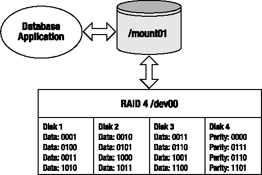
RAID 4 uses an XOR operation to generate the parity information. For each stripe in Figure A-5, the parity information is generated as follows:
Disk1 XOR Disk2 XOR Disk3 = Parity
----- --- ----- --- -----   ------
0001  XOR 0010  XOR 0011  = 0000
0100  XOR 0101  XOR 0110  = 0111
0111  XOR 1000  XOR 1001  = 0110
1010  XOR 1011  XOR 1100  = 1101
Tip
See the earlier "Generating Parity" section for details on how an XOR operation works.
RAID 4 requires that parity information be generated and updated for each write. Therefore, writes take longer in a RAID 4 configuration than a RAID 0 write. Reading from a RAID 4 configuration is fast because the data is spread across multiple drives (and potentially multiple controllers).
With RAID 4 you get more realized disk space than you do with RAID 1. The RAID 4 amount of disk space available to the application is calculated with this formula:
(Number of disks - 1) * Disk Capacity
For example, if you have four 100GB disks, then the realized disk capacity available to the application is calculated as shown here:
(4 −1) * 100 gigabytes = 300 gigabytes
In the event of a single disk failure, the remaining disks of the array can continue to function. For example, say Disk 1 fails. The Disk 1 information can be regenerated with the parity information, as shown here:
Disk2 XOR Disk3 XOR Parity = Disk1
----- --- ----- --- ------   -----
0010  XOR 0011  XOR 0000   = 0001
0101  XOR 0110  XOR 0111   = 0100
1000  XOR 1001  XOR 0110   = 0111
1011  XOR 1100  XOR 1101   = 1010
During a single disk failure, RAID 4 performance will be degraded because the parity information is required for generating the data on the failed drive. Performance will return to normal levels after the failed disk has been replaced and its information regenerated. In practice, RAID 4 is seldom used because of the inherent bottleneck with the dedicated parity disk.
RAID 5 is sometimes referred to as distributed parity. RAID 5 is similar to RAID 4 except that RAID 5 interleaves the parity information among all the drives available in the disk array. A RAID 5 configuration minimally requires three disks: two for data and one for parity. The term RAID 5 does not mean there are five disks in the array; there can be three or more disks in a RAID 5 configuration.
Figure A-6 shows a four-disk RAID 5 array. The first stripe of data consists of 000100100011. Three chunks of 0001, 0010, and 0011 are written to Disks 1, 2, and 3 with the parity of 0000 written to Disk 4. The second stripe writes its parity information to Disk 1, the third stripe writes its parity to Disk 2, and so on.

RAID 5 uses an XOR operation to generate the parity information. For each stripe in Figure A-6, the parity information is generated as follows:
0001  XOR 0010  XOR 0011  = 0000
0100  XOR 0101  XOR 0110  = 0111
0111  XOR 1000  XOR 1001  = 0110
1010  XOR 1011  XOR 1100  = 1101
Tip
See the earlier "Generating Parity" section for details on how an XOR operation works.
Like RAID 4, RAID 5 writes suffer a slight write performance hit because of the additional update required for the parity information. RAID 5 performs better than RAID 4 because it spreads the load of generating and updating parity information to all disks in the array. For this reason, RAID 5 is almost always preferred over RAID 4.
RAID 5 is popular because it combines good I/O performance with fault tolerance and cost effectiveness. With RAID 5 you get more realized disk space than you do with RAID 1. The RAID 5 amount of disk space available to the application is calculated with this formula:
(Number of disks - 1) * Disk Capacity
Using the previous formula, if you have four 100GB disks, then the realized disk capacity available to the application is calculated as follows:
(4 −1) * 100 gigabytes = 300 gigabytes
RAID 5 provides protection against a single disk failure through the parity information. If one disk fails, the information from the failed disk can always be recalculated from the remaining drives in the RAID 5 array. For example, say Disk 3 fails; the remaining data on Disk1, Disk 2, and Disk 4 can regenerate the required Disk 3 information as follows:
DISK1 XOR DISK2 XOR DISK4 = DISK3
----- --- ----- --- -----   -----
0001  XOR 0010  XOR 0000  = 0011
0111  XOR 0100  XOR 0110  = 0101
0111  XOR 0110  XOR 1001  = 1000
1010  XOR 1011  XOR 1100  = 1101
During a single disk failure, RAID 5 performance will be degraded because the parity information is required for generating the data on the failed drive. Performance will return to normal levels after the failed disk has been replaced and its information regenerated.
The RAID 0, RAID 1, and RAID 5 architectures are the building blocks for more sophisticated storage architectures. Companies that need better availability can combine these base RAID technologies to build disk arrays with better fault tolerance. Some common hybrid RAID architectures are as follows:
RAID 0+1 (striping, then mirroring)
RAID 1+0 (mirroring, then striping)
RAID 5+0 (RAID 5, then striping)
These configurations are sometimes referred to as hybrid or nested RAID levels. Much like Lego blocks, you can take the underlying RAID architectures and snap them together for some interesting configurations that have performance, fault tolerance, and cost advantages and disadvantages. These technologies are described in detail in the following sections.
Note
Be aware that there exists some degree of confusion on the naming standards for various RAID levels. The most common industry standard for nested RAID levels is that RAID A+B means that first RAID level A is built and then RAID level B is layered on top of RAID level A. This standard is not consistently applied by all storage vendors. You'll have to carefully read the specifications for a given storage device to ensure that you understand which level of RAID is in use.
RAID 0+1 is a disk array that is first striped and then mirrored (a mirror of stripes). Figure A-7 shows an eight-disk RAID 0+1 configuration. Disks 1 through 4 are written to in a striped fashion. Disks 5 through 8 are a mirror of Disks 1 through 4.

RAID 0+1 provides the I/O benefits of striping while providing the sturdy fault tolerance of a mirrored device. This is a relatively expensive solution because only half the disks in the array comprise your usable disk space. The RAID 0+1 amount of disk space available to the application is calculated with this formula:
(Number of disks in stripe) * Disk Capacity
Using the previous formula, if you have eight 100GB drives, with four drives in each stripe, then the realized disk capacity available to the application is calculated as shown here:
4 * 100 gigabytes = 400 gigabytes
The RAID 0+1 configuration can survive multiple disk failures only if the failures occur within one stripe. RAID 0+1 cannot survive two disk failures if one failure is in one stripe (/dev01) and the other disk failure is in the second stripe (/dev02).
RAID 1+0 is a disk array that is first mirrored and then striped (a stripe of mirrors). Figure A-8 displays an eight-disk RAID 1+0 configuration. This configuration is also commonly referred to as RAID 10.

RAID 1+0 combines the fault tolerance of mirroring with the performance benefits of striping. This is a relatively expensive solution because only half the disks in the array comprise your usable disk space. The RAID 1+0 amount of disk space available to the application is calculated with this formula:
(Number of mirrored devices) * Disk Capacity
For example, if you start with eight 100GB drives and you build four mirrored devices of two disks each, then the overall realized capacity to the application is calculated as follows:
4 * 100 gigabytes = 400 gigabytes
Interestingly, the RAID 1+0 arrangement provides much better fault tolerance than RAID 0+1. Analyze Figure A-8 carefully. The RAID 1+0 hybrid configuration can survive a disk failure in each stripe, and it can also survive one disk failure within each mirror. For example, in this configuration, Disk 1a, Disk 2b, Disk 3a, and Disk 4b could fail, but the overall device would continue to function because of the mirrors in Disk 1b, Disk 2a, Disk 3b, and Disk 4a.
Likewise, an entire RAID 1+0 stripe could fail, and the overall device would continue to function because of the surviving mirrored members. For example, Disk 1b, Disk 2b, Disk 3b, and Disk 4b could fail, but the overall device would continue to function because of the mirrors in Disk 1a, Disk 2a, Disk 3a, and Disk 4a.
Many articles, books, and storage vendor documentation confuse the RAID 0+1 and RAID 1+0 configurations (refer to one when really meaning the other). It's important to understand the differences in fault tolerance between the two architectures. If you're architecting a disk array, ensure that you use the one that meets your business needs.
Both RAID 0+1 and RAID 1+0 architectures possess the excellent performance attributes of striped storage devices without the overhead of generating parity. Does RAID 1+0 perform better than RAID 0+1 (and vice versa)? Unfortunately, we're going to have to waffle a bit (no pun intended) on the answer to this question—it depends. Performance characteristics would be dependent on items such as the configuration of the underlying RAID devices, amount of cache, number of controllers, I/O distribution of the database application, and so on. We recommend you perform an I/O load test to determine which RAID architecture works best for your environment.
RAID 5+0 is a set of disk arrays that is first placed in a RAID 5 configuration and then striped. Figure A-9 displays the architecture of an eight-disk RAID 5+0 configuration.
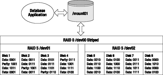
RAID 5+0 is sometimes referred to as striping parity. The read performance is slightly less than the other hybrid (nested) approaches. The write performance is good, though, because each stripe consists of a RAID 5 device. Because this hybrid is underpinned by RAID 5 devices, it is more cost effective than the RAID 0+1 and RAID 1+0 configurations. The RAID 5+0 amount of disk space available to the application is calculated with this formula:
(Number of disks - number of disks used for parity) * Disk Capacity
For example, if you start with eight 100GB disks, with four disks in each RAID 5 device, then the total realized capacity would be calculated as shown here:
(8 - 2) * 100 gigabytes = 600 gigabytes
RAID 5+0 can survive a single disk failure in either RAID 5 device. However, if there are two disk failures in one RAID 5 device, this will result in a failure of the entire RAID 5+0 device.
Which RAID technology is best for your environment? It depends on your business requirements. Some storage gurus say use RAID 5 for databases, and others argue never to use RAID 5. There are valid arguments on both sides of fence. You may find yourself in a shop that already has a group of storage experts that predetermine the underlying disk technology without input from the DBA team. Ideally, you would like to be involved with architecture decisions that affect the database, but realistically that does not always happen.
Or you may find yourself in a shop that is constrained by cost and might reach the conclusion that a RAID 5 configuration is the only viable architecture. For your database application, you'll have to determine the cost-effective RAID solution that performs well while also providing the required fault tolerance. This will most likely require you to work with your storage experts to monitor disk performance and I/O characteristics.
Tip
See Chapter 8 for details on how to use tools like iostat and sar for monitoring disk I/O behavior.
Table A-2 summarizes the various characteristics of each RAID technology. These are general guidelines. Before you implement a production system, test the underlying architecture to ensure it meets your business requirements.
Table A-2. Comparison of RAID Technologies
Disk Technology | Read | Write | Fault Tolerance | Cost |
|---|---|---|---|---|
RAID 0 | Excellent | Excellent | Bad | Low |
RAID 1 | Good | Slow | Very Good | High |
RAID 4 | Good | Good | Good | Low |
RAID 5 | Good | Good | Good | Low |
RAID 0+1 | Good | Good | Very Good | High |
RAID 1+0 | Good | Good | Excellent | High |
RAID 5+0 | Good | Good | Good | Medium |
Table A-2 is intended only to provide you with general heuristics for determining the appropriate RAID technology for your environment. There will be some technologists who might disagree with some of these general guidelines. From our experience, there are often two very opposing RAID opinions that both have valid points of view.
There are also variables that are unique to a particular environment that also influence what the best solution is. For this reason, it can be difficult to determine exactly which combination of chunk, stripe size, stripe width, underlying RAID technology, and storage vendor will work best over a wide variety of database applications. If you have the resources to test every permutation under every type of I/O load, then you probably can determine the perfect combination of the previously mentioned variables.
Realistically, few shops have the time and money to exercise every possible storage architecture for each database application. You'll have to work with your system administrator and storage vendor to architect a cost-effective solution for your business that performs well over a variety of database applications.
Warning
Using RAID technology does not eliminate the need for a backup and recovery strategy. You should always have a strategy in place to ensure that you can restore and recover your database. You should periodically test your backup and recovery strategy to make sure it protects you in the event all disks fail (because of a fire, earthquake, tornado, avalanche, grenade, hurricane, and so on).
DBAs are often involved with disk storage capacity planning. DBAs need to ensure that adequate disk space will be available (both initially and for future growth) when the database server disk requirements are first spec'ed out (specified). When using RAID technologies, you need to be able to calculate the actual amount of disk space that will be available given the available disks.
Table A-3. Calculating the Amount of RAID Disk Space Realized
Disk Technology | Realized Disk Capacity |
|---|---|
RAID 0 (striped) | Num Disks in Stripe * Disk Size |
RAID 1 (mirrored) | Num Mirrored Arrays * Disk Size |
RAID 4 (dedicated parity) | (Num Disks - 1) * Disk Size |
RAID 5 (distributed parity) | (Num Disks - 1) * Disk Size |
RAID 0+1 (striped, then mirrored) | Num Disks in Stripe * Disk Size |
RAID 1+0 (mirrored, then striped) | Num Mirrored Arrays * Disk Size |
RAID 5+0 (RAID 5, then striped) | (Num Disks - Num Parity Disks) * Disk Size |
Be sure to include in your disk space calculations the future database growth requirements. Also consider the amount of disk space needed for files such as database transaction logs and database binaries, as well as the space required for database backups (keep in mind you may want to keep multiple days worth of backups on disk).
Tip
A good rule of thumb is to keep one database backup on disk at all times and then back up the database backup files to tape (and then move the backup tapes offsite). This provides you with good performance that is required for routine backup and recovery tasks and also provides protection against complete disasters.
RAID is a cost-effective technology that underpins highly scalable and efficient storage systems. This technology provides you with a way to distribute the database I/O load over several disks and controllers. RAID also gives you a high degree of fault tolerance for disk devices. This allows you to build heavily used databases that perform well and are highly available.
As a DBA you should be somewhat knowledgeable of basic RAID concepts. This will enable you to clearly communicate your database performance and availability requirements with system administrators and storage experts. You don't have to be a RAID expert, but it helps to know what terms mean and how they can impact your database.
When planning for capacity requirements, it's helpful to understand the difference between the number of physical disks in a RAID device and the actual realized space made available to the application. An understanding of the costs vs. the benefits of each RAID technology will allow you to make better storage decisions in regard to database performance and availability.