CHAPTER 10 Working with Phasing, Groups, and Design Options
Projects will progress through various stages during design and construction. As a result, it’s sometimes necessary to distinguish the element of time within your project: when something is created, if it is demolished, and what it will look like when the project is complete. Beyond just phasing, design is also about maintaining relationships between repetitive elements. Sometimes this repetitive element can be a single component in your project, such as a light or a piece of furniture. But it can also be an entire collection of elements, such as a typical room in a hotel or hospital.
Another fundamental aspect of design is the iteration of options. You have to be able to see many ideas simultaneously and in context with other ideas. The client and contractor need to see options and alternates. It’s important that these options not be fully independent, separate files so that the results can be analyzed and compared.
This chapter focuses on these three concepts: time, repetition, and iteration of options. In Autodesk® Revit® Architecture software, they’re addressed with phasing, groups, and design options, respectively.
In this chapter, you’ll learn to:
Use the Phasing tools to create, demolish, and propose a new design
Understand and utilize groups
Create and use design options
Using Phasing
Phasing is the software’s method of allowing you to add the element of time to objects in your project. It’s easy to think of an architectural design in terms of what something is, where something is, and how it will be assembled. Phasing adds the dimension of when something is, which is incredibly useful and powerful.
Phases are most useful for doing the kinds of tasks that require you to show when elements are being introduced into your design: showing demolition and new construction in an existing building, or showing different drawing packages as examples. But a few words of caution and clarification: We don’t recommend using extensive phasing to simulate construction sequencing, which is sometimes referred to as 4D. It might seem like a great idea at first, but ultimately it will degrade the performance of your model and lead to confusion across your project team.
There’s a far more efficient method of simulating construction sequences that allows model elements to be scheduled, viewed, and even color-coded based on the sequence value that you define: project parameters.
By using project parameters, you’re able to create and assign an instance parameter value to everything in your project that you’d want to assign a construction sequence, as shown in Figure 10.1.
Figure 10.1 Creating a construction sequence instance parameter for project geometry
Once you’ve created this instance parameter, you’ll be able to create view filters that override the default display style of an object based on the parameter value, as shown in Figure 10.2. Each construction week value is assigned to a filter rule.
Combined with visibility and graphic overrides, you’re able to create a filter that modifies the graphics based on a parameter, as shown in Figure 10.3.
Figure 10.3 Applying filters to graphic override settings
As a result of applying parameter-based filters, you will be able to modify the graphics of a view to illustrate some metadata about the objects in a far more flexible and predictable way than the phasing functionality, as shown in Figure 10.4. Another benefit is that this technique is not limited to views of geometry. View filters can be applied to any view, including schedules, which will allow you to group and filter schedules based on your unique project parameter.
Figure 10.4 Using parameters and view filters to override graphics
Now that you understand a better way to create sequencing in Revit using parameters and filters, we’ll discuss how phasing is best used. To work along with the steps in the following section, download and open the file c10-Phases-Start.rvt from this book’s web page at www.sybex.com/go/masteringrevit2017.
What Can You Phase?
All modeled elements in Revit have two parameters associated with phasing: Phase Created and Phase Demolished. When you place geometry in a view, the Phase Created property by default is the phase assigned to that view. For example, if your view is set to Phase Existing, all elements you place in that view will automatically be assigned to the Existing phase. After an element is placed in the project, the phase can always be changed in the Properties palette, as shown in Figure 10.5.
Figure 10.5 Changing the phase of geometry (near the bottom of the dialog box)
Rooms also have phasing properties, but there is an important difference: The Phase property of a room cannot be changed after it is placed. As shown in Figure 10.6, the phase is shown in the Properties palette, but it is read only. If you want to change the phase of a room, you’ll need to delete and re-create the room in a view that is assigned the desired phase. You also might find it faster to press Ctrl+X to cut the rooms from one view and then press Ctrl+V to paste them into a view that has been set to the desired phase.
Figure 10.6 The phase of a room may not be changed after placement.
The phase of an element when initially placed is often confusing to a new user, but it is quite simple: The phase of the view that you’re placing the element into determines the element’s phase, as shown in Figure 10.7. This is more critical for rooms than for building elements because the phase of a building element can be changed after placement. But there may be occasions when you’re placing many elements that you intend to be in a particular phase, and you’ll want to create a view with that phase active. This will allow you to place elements in that view and not worry about changing their phase later.
Applying the notion of time to your project may seem complicated, but it is quite simple to implement. You need to understand three basic aspects about the settings related to phasing:
What are the major phases of your project?
How will you use the phasing properties to filter views within your project documentation?
What is the graphic convention to convey an object’s phase?
These aspects are expressed in the three tabs of the Phasing dialog box. On the Manage tab of the ribbon, click the Phasing button to open the Phasing dialog box, shown in Figure 10.8.
In the most common of phased projects, you’ll have views to illustrate Existing, Demolition, and New Construction conditions. On more complex projects, you might have several stages of new construction as you build out larger facilities. Because this dialog box shows only Existing and New Construction, new users will mistakenly create a new phase for Demolition. As we’ll demonstrate later, demolished elements are represented with phase filters, not as a dedicated project phase.
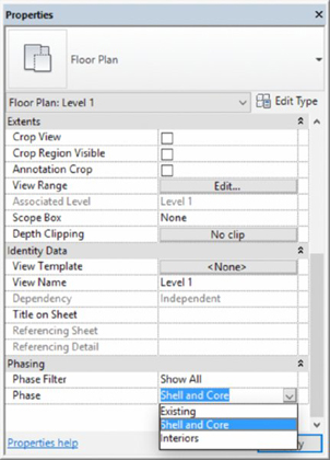
So, when do you need to create more than the phases shown by default? As one example, think of a staged construction project that will happen in two new phases. In this scenario, you are designing with a start time for the building shell followed by another phase for interiors, allowing the owner to split funding for the project into two budgets. In phase one, the building core and shell are built. In the second phase, interior construction occurs. Your first phase is labeled Shell and Core. Your other phase is labeled Interiors. This phasing also gives a contractor who is familiar with Revit the ability to use the model to see what needs to be built and when. Depending on how your model is created, the contractor can even do cost estimates by phase.
In the Project Phases tab of the Phasing dialog box, create the two phases as we just described (Figure 10.9). You can simply rename the New Construction phase Shell and Core. Click the Insert After button to create an additional project phase and then rename it Interiors. We’ll use these in a sample exercise in a moment. When you’re creating phases, you might notice there’s no Delete button. You can’t delete a phase once you’ve added it because you don’t want to delete any geometry placed on a phase. Should your planning process change and you want to eliminate a phase, you can merge two phases using either of the Combine With buttons on the right.
Click OK to accept the changes and close the Phasing dialog box, and then activate the Level 1 floor plan. Once you’ve created these additional project phases, pick any project geometry and look at its instance parameters. You’ll notice in the Properties palette that it can be assigned to any one of these three phases, as shown in Figure 10.10.
Return to the Manage tab in the ribbon and once again click the Phasing tool. The middle tab in the Phasing dialog box is Phase Filters (Figure 10.11). Seven predefined phase filters are listed.
Figure 10.11 The Phase Filters tab with seven predefined phase filters
Don’t be concerned if the filter names seem a bit cryptic at first. What’s really important is the four graphic conditions that can be overridden: New, Existing, Demolished, and Temporary. Let’s take a moment to explore how these graphic conditions are applied to a virtually unlimited number of user-defined project phases. Any object you place into a project has certain states relative to any particular phase. In other words, you might ask the following questions about a model element:
Was it created in the current phase? That’s new.
Was it created in a previous phase? That’s existing.
Was it created in a previous phase and demolished in the current phase? That’s demolished.
Is the object created and demolished in the same phase? That’s temporary.
As you can see, phase filters are relative settings. That is, the filters are relative to the phasing properties of the object and the phase of the view in which the object is displayed. Also realize that although phases are applied to elements, phase filters are applied only to views.
Now let’s explore the predefined ways a phase filter can be applied. Select any of the drop-down menus, as shown in Figure 10.12. You’ll notice that the phase filter can override the graphics in one of three ways:
By Category: The object can be shown by its category settings or not overridden. It will be displayed in the project just as it does by default.
Overridden: This means that you can define a graphic override for that object. We’ll get into the graphic overrides in a moment.
Once you understand how each of the phase filters displays objects, phases can begin to make sense. For example, the Show Complete phase filter shows New and Existing elements By Category. But Demolished and Temporary elements are not displayed at all. Use this setting when you want to show the model in a finished condition. Another example is to use the Show New phase filter in a schedule such as in a door schedule. The Show New filter will include only those doors that are assigned to the phase that is also assigned to the schedule. The schedule will not list any existing doors or doors that were demolished.
If there’s any remaining confusion, it probably involves the naming convention of Show Previous + Demo. A better name might be Show Existing + Demolition, but Existing is a bit misleading because this setting is showing the previous phase, which is not necessarily existing elements. They might be temporary elements that need to be demolished. Therefore, Show Previous makes more sense.
USING GRAPHIC OVERRIDES
The Graphic Overrides tab is the final tab in the Phasing dialog box (Figure 10.13). This dialog box relates back to the Overridden assignment of the previous tab.
This tab allows you to override geometry in a few areas: the Lines and Patterns characteristics of Projection/Surface and Cut (which refers to the cut profile of objects). You also have the option to just halftone the element. Finally, you can assign a unique Material setting when rendering. Although this ability is helpful for rendering with phase information, it can also be useful for rendering everything to a matte material, something we discuss in Chapter 11, “Visualization.” As it is, phasing can show you where you are (new construction) and where you’re coming from (existing), but not where you’re going (future).
Illustrating the Geometry Phase
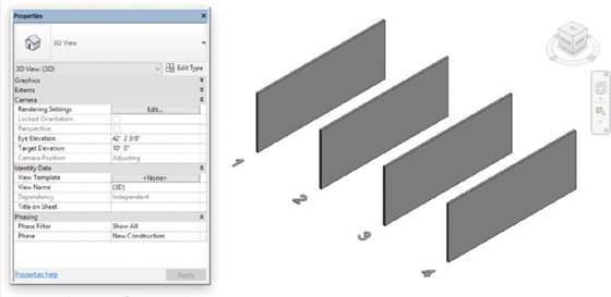
Here’s a simple exercise to illustrate each of the phases in a single view. Download and open the c10-Phases-Start.rvt file from the book’s companion web page if you have not already done so. Activate the default 3D view (Figure 10.14).
By default, all of these walls have been created in the New Construction phase because the phase of the view is New Construction. Now, selecting each of the walls from left to right, associate them with each of the following phase settings:
Wall 2: Phase Created: Existing/Phase Demolished: New Construction
Wall 3: Phase Created: New Construction/Phase Demolished: None
Wall 4: Phase Created: New Construction/Phase Demolished: New Construction
In Figure 10.15, you’ll notice that Wall 1 (Existing/Phase Demolished: None) and Wall 3 (New Construction/Phase Demolished: None) look similar. Graphically, this might not be enough to demonstrate the different phases, so let’s change the graphic properties of the Existing wall so it’s visually more distinct.
From the Manage tab in the ribbon, click Phases; then click the Graphic Overrides tab. Next, select the option to open the Material setting for the Phase - Exist material. You’ll click the far right of the Phase-Existing box in the Material column. This opens the Material Browser dialog box highlighting the Phase - Exist material (Figure 10.16).
Select the Appearance tab to modify the rendered appearance of the material (Figure 10.17). Click the gray bar that reads RGB 80 80 80 to open the Color dialog box.
In the Color dialog box, assign a lime-green color with the following RGB values: Red = 0, Green = 255, Blue = 0 (Figure 10.18). Click OK to close the Color dialog box.
Switch to the Graphics tab and under the Shading properties, check the Use Render Appearance box. This setting will use the coloring of the render material for shaded views as well. Click OK to close the Material Browser. When you finish changing these settings, you’ll have the result shown in Figure 10.19, with each phase shown distinctively within the view.
Once you settle on a color and graphic scheme, we recommend making this particular setting part of your default project template or your office’s standards. That way, new users will be able to distinguish the phase of an object far more clearly, and the standard will be consistent throughout your office.
Using the View Phase
Now that we’ve discussed the phasing properties of geometry, we’ll cover the phase properties of the views. Starting with the 3D view from the previous example, examine the view properties in the Properties palette, provided there are no model elements selected (Figure 10.20). We have collapsed some of the property groups at the top to show the Phasing properties at the bottom of the list.
Remember that all the graphic overrides and filters for phasing are relative to the phase that is assigned to geometry or a view. By default, the New Construction phase is assigned to new views created in your project. This phase assignment can be changed at any time from the Properties palette. The phase property can also be assigned to a view template for easier management of this parameter.
The next important step is to apply the most appropriate phase filter. To illustrate how a phase filter changes the way objects are displayed in a view, you will step through several filters in the following exercises.
The default phase filter is Show All (Figure 10.21). This filter will show all the model elements relative to the phase assigned to the view and will override their graphics based on their Phase Created and Phase Demolished parameters. It also gives you a sense of all the elements as they exist in time.
Figure 10.21 Show All phase filter for the New Construction phase
Although this is great for 3D views, where every phase has a distinct color, it’s also useful for working in a plan, elevation, or section. To turn this graphic visibility on, activate the Level 1 floor plan from the Project Browser and change the Graphic Display setting to Shaded or Consistent Colors. You’ll be able to clearly distinguish between objects in different phases, as shown in Figure 10.22.
Now let’s start moving through each of the phase filters. But here’s an important note: Rather than moving through the various phase filters from top to bottom, let’s move through time by changing the Phase parameter.
Return to the 3D view and keep the Phase Filter set to Show All, but change the Phase to Existing (Figure 10.23). This will show only the objects created in the Existing phase—and their graphics are not overridden. The two walls that were assigned to the New Construction phase are not shown in the view because Revit does not provide a way to see future construction beyond the phase assigned to the view.
Figure 10.23 Show All phase filter for the Existing phase
Set the phase of the view back to New Construction and set the phase filter to Show Previous + Demo (Figure 10.24). This filter still shows only the existing walls (the walls from the previous phase). One of the walls is clearly being demolished. Keep in mind that the graphic overrides that are being applied are relative to what you’d be seeing through the lens of the New Construction phase.
We’ll move forward another moment in time and set the phase filter to Show Previous + New. This shows only the remaining elements (not any of the demolished content) from the present and previous views (Figure 10.26). It is not always necessary to click Apply in the Properties palette each time you want to apply the settings you’ve just changed. Moving your mouse pointer outside the palette has the same effect as clicking Apply.
This visualization brings up another interesting point: Why not show the remaining existing elements as well as the proposed and temporary elements? Although you could also create a new phase filter, for this example we’ll change the settings of the Show Previous + New graphic phase filter (Figure 10.27). From the Manage tab on the ribbon, click the Phases tool again. Choose the Phase Filters tab, and in the Show Previous + New row, go to the Temporary column and change the setting to Overridden.
Click OK to exit the dialog box. Figure 10.28 shows the result.
Figure 10.28 Show Previous + New phase filter with temporary elements added
The next step in the sequence is to set the view to Show Demo + New, which will show demolished elements from the present phase as well as any new elements from the present phase (see Figure 10.29). The numbers disappeared because they are Model Text elements that were placed on the Existing phase.
Moving forward in time, let’s now show only the elements in the New Construction phase. Set the phase filter to Show New and only one wall will be displayed, as shown in Figure 10.30.
Now comes the final phase filter setting, Show Complete (Figure 10.31). This shows only the existing elements that were not demolished in previous phases up to the phase assigned to the view. Elements that are demolished in any phase are not displayed, and neither existing nor new elements are overridden. This phase filter is most often used for camera views where a rendering of the finished conditions may need to be generated without any sort of graphic overrides.
It’s easy to think of groups as functionally similar to blocks in Autodesk® AutoCAD® software or cells in Bentley MicroStation, but groups can be much more. They are great at maintaining repetition within your project, but there are some major differences:
Creating groups is quite easy. And whether it’s a 2D or 3D group, the insertion point for the group is easily defined and modified. The same can’t be said of simple 2D blocks in other applications.
Updating groups is a breeze. It’s easy and intuitive to modify a group after it’s been created. Practically anyone on your team can do it, which means that design workflow will not bottleneck in your project team.
Copying groups throughout your project is also a breeze. Groups can be copied across different levels, rotated, and even mirrored. We cover groups in more detail later in this chapter.
There are a few good practices that you’ll want to keep in mind when using groups. But they’re so straightforward that you’ll wonder how you’ve ever worked without them.
Creating Groups
You can create two kinds of groups in Revit. One kind is just for geometry, and these groups are called model groups. The other is just for view-specific content like text, tags, dimensions, and so on, and these groups are called detail groups. You can create one kind of group or the other explicitly. But if you try to create a group with both model and detail elements, Revit is smart enough to create a separate detail group that’s associated with the model group.
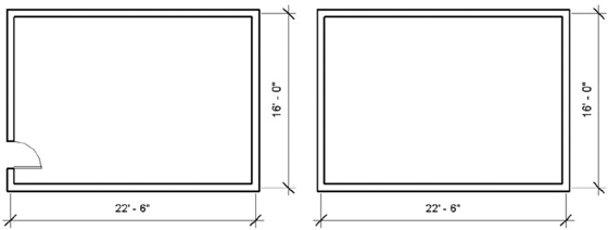
To demonstrate this, download and open the file c10-Groups-Start.rvt or c10-Groups-Start-Metric.rvt from this book’s web page. Activate the Level 1 floor plan and you will see four walls with dimensions, as shown in Figure 10.32.
Select the walls and dimensions in the view, and click the Create Group button on the contextual ribbon in the Create panel. Keep the default name, Group 1, for both Model Group and Attached Detail Group (Figure 10.33).
Figure 10.33 Creating the model and attached detail group
Now select the group of walls and copy it to the side of your original group. You’ll notice that only the model-based group is copied, which is fine for now (Figure 10.34).
It is a simple process to associate the detail group to another instance of the model group. Select the group and then click the Attached Detail Groups button on the Group panel in the contextual ribbon, and you’ll see the dialog box shown in Figure 10.35. Select the check box for Group 1 from the list and click OK.
Figure 10.35 Attached Detail Group Placement dialog box
The results are fairly straightforward (Figure 10.36). Both groups are now identical with geometry and dimensions.
Now that you’ve created two identical groups, let’s add a door to one of the walls that belong to the group, as shown in Figure 10.37. But don’t add the door to the group—just place it in one of the walls as you would with any nongrouped wall.
Figure 10.37 Adding a door outside of Edit Group mode
Now select the group to the left (the one with the new door) and select Edit Group from the Group panel in the contextual tab of the ribbon. You’ll enter a special editing environment, shown in Figure 10.38, and the nongrouped elements will be grayed out. The screen overlay color alerts you that you are in Edit Group mode. The screen will appear with a yellow background in this mode. Here you’ll be able to add, remove, and attach other elements to your group.
Now add the door to the group by selecting the Add function from the Edit Group panel. When you add an element to the group, it will appear black in the Edit Group mode, letting you know you were able to successfully add it to your group. You’ll notice that you can’t add the door numbers because this is a model group and tags are 2D components. Now finish the group by clicking the Finish button (the green check), and you’ll notice that both groups now have a door in the same location (Figure 10.39).
The process is essentially the same for modifying any group: Start the Edit Group mode, make the changes and/or additions, and then finish the group.
Creating New Groups
Sometimes the easiest way to make a new group is to copy and modify an old one. A quick way to do this is to right-click the name of the group you want to duplicate in the Project Browser and choose Duplicate from the context menu, as shown in Figure 10.40. Complete this command and make sure the new group is named Group 2 in the Project Browser.
Return to the plan view and select your group. Notice in the Type Selector that you can swap between groups in the same way you can swap between types within a family. Choose Group 2 in the Type Selector so you have one of each group type on the screen.
With Group 2 still selected, click Edit Group from the contextual tab in the ribbon. Edit it by making it 13’-6” square (4 m), as shown in Figure 10.41; then finish the group.
Groups have insertion points that you need to consider before you exchange one group for another. When you create a group, the insertion point is initially at the geometric center of all the elements in the group. The group’s origin is also identified by x- and y-coordinates.
But keep in mind that as you edit the group, the insertion point doesn’t move until you deliberately relocate it. This can be seen in Figure 10.42; editing the geometry for Group 2 retains the same insertion point that was active when the group was initially created. Even though we’ve modified the group, the insertion point remains where it was originally when the group was created. (When editing this group, the left wall was moved to the right and the top wall was moved down to achieve the dimensions.)
Moving the insertion point is an easy matter of dragging (and, if necessary, rotating) the Insertion Point icon to a common location before swapping one group for another (Figure 10.43). Drag the insertion points for both Group 1 and Group 2 to the inside face of the walls at the lower-left corner.
Once you have adjusted the insertion points of multiple similar groups, swapping groups will occur at the same relative location. Figure 10.44 illustrates Group 1 being swapped for Group 2, and vice versa, but common insertion points are maintained. Select the instance of Group 1 in the floor plan and choose Group 2 from the Type Selector.
There will be occasions where everything in a group works great and it works throughout the project—except for that one particular case where a condition is slightly different. In the past, you had to create new groups for each slight exception, which might have been conceptually consistent but often led to a much longer list of group variants. You were left with little ability to cohesively modify them as the project size (and number of groups) continued to grow.
This workflow is now deftly handled by excluding individual elements from groups. The original group definitions remain intact, and schedules are aware of excluded elements. Figure 10.45 shows an example of this in practice. We’ve created another instance of Group 1; however, there’s a column right in the middle of the door.
Figure 10.45 A column location conflicts with the door in our sample group.
We don’t want to destroy the integrity of the group and give up being able to quickly modify similar elements, but we also cannot advance the design with the column located where it is shown. To resolve this, hover the mouse pointer over the door within the group and then press the Tab key until the door is highlighted, right-click it, and select Create Similar from the context menu. This will allow you to place a new door in a better location. This door will not be part of the group. In Figure 10.46, the new door has been placed above the grouped door, and its swing direction has been flipped.
Figure 10.46 Adding a new door using Create Similar
Now you can exclude the door that conflicts with the column as an exception to the original group definition. This process can be a bit confusing at first because you don’t need to enter Group Edit mode to exclude members from groups. Simply hover the mouse pointer over the door and press the Tab key until the door is highlighted. Select the door, as shown in Figure 10.47.
Once the door in the group is selected, you’ll notice an icon pointing to the door. Clicking this icon will allow you to exclude the door as an exception to the group. The icon will change and show a red hash through it. This means the element is now excluded and will automatically be deleted when you deselect the group. The wall will heal itself as if the door were never there.
How can you tell if a given group has elements that have been excluded? Selecting the group will reveal any hidden elements in the group that are excluded (Figure 10.48). Just tab through to select the hidden door to include the component back into the group.
Figure 10.48 Excluded group elements will display when the group is selected.
Saving and Loading Groups
Even though we stress the fact that Revit is a whole-process BIM application (by integrating the modeling, documentation, and multiuser workflow into one database), there are times when you’ll want to share the data across many files.
Just as you wouldn’t want your family components locked up inside a project file, there are good reasons to keep commonly used groups outside your project. You might even want to keep them in a folder just as you do your custom content so you can use them again on similar projects or as part of your office’s library. You can do so by saving groups outside your projects.
Saving groups is a simple matter of right-clicking the group name in your Project Browser and selecting Save Group (Figure 10.49).
Figure 10.49 Saving groups from the Project Browser
You’ll then be prompted to save the group as an RVT file. You can open this file as you would any other RVT file if you’d like to modify it later and then reload the group into the project in order to update all the instances. To load an external group into a project, go to the Insert tab in the ribbon. On the Load From Library panel, choose Load As Group.
Be aware that when you load the group in a project, if the group name already exists, you’ll be given a warning. You can overwrite the existing group (by selecting Yes) or load with the option to rename the group that’s being loaded (by selecting No). Or you can cancel the operation altogether (Figure 10.50).
What’s really great is that when you reload the group, Revit even remembers to exclude previously excluded elements from the group that’s been modified in another session. Figure 10.51 shows that a desk and chair have been added to Group 1 in the RVT file saved from the original group. The group has been reloaded, overwriting the original group, but the exclusion remains intact.
Because groups are also RVT files, they can be linked into the project environment as well. Although you can’t edit a link in place (as with a group), there are some excellent reasons why you might want to start a group as a link and then bind the link at a later time. Binding a linked project will convert it to a group. Groups and links can also exist within design options (more on design options later in this chapter). To follow this workflow, use these steps:
From the Insert tab in the ribbon, choose Link Revit from the Link panel (Figure 10.52).
Browse to the group you just exported and click Open.
Figure 10.52 Use the Link Revit command to add groups as links.
After the link has been placed, you can copy it throughout your project as you would any other element in Revit. Keep in mind that all the functionality between groups and non-grouped elements will not behave the same in links as it does throughout the rest of your project. For example, in Figure 10.53, the upper-right collection of walls and furniture is a link, not a group. As a result, walls are not cleaning up between linked models and groups in the same way they are between groups and other walls in the project.
This graphic restriction may not be a concern during early stages of design, when links allow for a lot of rapid flexibility. After you’ve resolved your design using linked models, you can bind them into the project environment by selecting each link in a view and clicking Bind Link from the contextual tab in the ribbon.
Rather than explode the linked model into separate and unrelated elements, Revit converts the link to a group. Once this happens, walls easily join across groups, as shown in Figure 10.54.
Figure 10.54 Wall joins are resolved when linked models are bound in the current project.
Using Best Practices for Groups
So far, you have learned that groups can help you maintain consistency among repeated elements and will facilitate additional design iteration; however, there are some important exceptions that you will want to note. Nearly every time a problem crops up with groups, it’s the result of ignoring one of the following best practices:
Don’t put datum objects in your group. Avoid putting datum objects (levels and grids) inside your group. First, you can’t manage the extents of the datum objects unless you’re in Edit Group mode, which can create conflicts elsewhere in your project. Of course, you will have the option to not include the datum objects when you bind your link. Again, doing so doesn’t necessarily create a technical hurdle, but it can create a lot of confusion. We’ve seen situations where duplicate levels were deleted only to find out that those levels were hosting content in the project.
Don’t nest groups. In other words, avoid creating groups within other groups. Although nesting can save time in some situations when the design is preliminary and your team is trying to distribute content and design ideas quickly, you’ll likely find a point of diminishing returns as the design evolves. You can’t get to all the features and functionality of Revit when you’re in Edit Group mode. And if you’re nested deep into groups and trying to modify project properties, you’ll quickly get frustrated digging in, out, and across nested groups to go back and forth between your group and the project.
Group hosted elements and their hosts together. Always keep your hosted elements and hosts together. For example, do not group doors and windows without the walls that are hosting them. If any of the windows in a group become unhosted from walls and then deleted, this will delete the respective windows in all other group instances—even if they are properly hosted.
Don’t use attached relationships in groups. The top constraints of walls are commonly attached to levels or other hosts like floors and roofs, but these relationships should be avoided in groups. If you manipulate the datum or attached host and the relationship creates inconsistent conditions among the instances of the group, you’ll see a warning asking you to fix the groups (Figure 10.55).
Fixing the group really doesn’t fix the group. It actually explodes it or creates a new group that is no longer referenced to the first group (Figure 10.56).
Don’t mirror groups. Finally, and maybe most important, don’t mirror groups. Instead, it’s better to create left and right versions. Does mirroring work in concept? Yes. Does it work in the real world? Not really.
Think about it. You’d love to be able to mirror that prototype coffee shop, right? Mirror the coffee shop—and all the equipment in the group—and now the baristas are foaming milk on the right rather than the left. This might look great in a rendering, but it doesn’t make sense for the company that manufactures the espresso machines.
And now the display cases have power supplies on the wrong side. The cash register has keys on the wrong side. The desk in the manager’s office now has drawers on the left and filing cabinets on the right. And to make matters worse, the sink in the bathroom now has hot water coming from the wrong faucet. Again, it makes all the conceptual sense in the world to be able to mirror a building—and a group. But trying to make it work can cost a lot of time and money. And that’s just a coffee shop. If you think it’s a good idea to mirror a hospital room or a surgical theater or some other mission-critical building or civil construct, well, it could end badly. Or you will have to work very, very late to resolve the issues.
If you’d like to download the file that has been created during the examples, you can find it in the Chapter 10 folder on the book’s web page; the file is called c10-Groups-Finished.rvt.
Making Design Options for Design Iteration
Revit software provides a unique set of tools for developing multiple design iterations in the confines of a single-model environment. You can use these tools to explore alternative designs without the need to save multiple independent versions of your model as you move in different directions. You’re free to investigate multiple roof configurations or different entry canopies or to explore various furniture, office layouts, and stairs—quite literally anything that can be modeled. This functionality also allows you to create views that show each option so multiple designs can be compared.
Let’s begin by establishing a fundamental understanding of the workflow for design options. First, you have a main model, which includes all the elements you’ve learned how to model so far in this book. The main model can be thought of as a backdrop or stage on which different options are displayed. Elements in the main model are always visible by default, whereas design options come and go, appearing and disappearing depending on which design option you’re editing or viewing. Put another way, the main model includes everything else that’s not in the design options.
You begin to explore design options by first creating a named option set—for example, Canopy Options. Within the option set, you then define options, the first of which is the primary option. Each option can be named to help you identify the intent, such as Glass Canopy and Steel Canopy. From here, you need to either select elements you’ve already modeled and add them to the appropriate design options or edit each option and create the elements with the Design Options tool active. Either way, the primary option in each option set will be displayed throughout your project by default. You can make as many options as you need—there is no limit.
The last part of configuring design options is to create some additional views in which to compare the ideas. As soon as you start creating design options in a project, the Design Options tab is added to the Visibility/Graphic Overrides dialog box. In this interface, you can select a specific option to be displayed for any of the option sets in the project. You can then present them to a client, to the project architect, or to other stakeholders in the design process. At any time, you may set any other option as the primary option. This will affect any views that are displaying the default option.
When an option within a set is finalized, you can accept the primary design solution and add it back to the main model. Doing so deletes all elements in the other options within the option set and merges your accepted option back into the main model.
Creating Design Options
Let’s now explore the use of design options with a simple exercise. Download and open the file c10-DesignOptions-Start.rvt or c10-DesignOptions-Start-Metric.rvt from this book’s web page. The sample files have a simple layout of walls, as shown in Figure 10.57.
Figure 10.57 Create a simple layout of walls to begin studying design options.
Starting in the Level 1 view, you’re going to configure this simple space into a design option that divides the space vertically in one option and horizontally in the other:
From the Manage tab in the ribbon, locate the Design Options panel (Figure 10.58) and then click the Design Options button.
You can also access the Design Options tool from the status bar at the bottom of the application window.
In the Design Options dialog box, click New in the Option Set area to create a new option set. This will automatically create one design option within the set.
Click New in the Option area of the dialog box to create an Option 2 option, as shown in Figure 10.59. Click Close to dismiss the dialog box.
Now that you’ve started creating design options, everything in the project is considered the main model. You can start adding elements to one of the two options.
Select the center wall, which will immediately initiate the Modify | Walls contextual tab in the ribbon.
With the wall segment selected, you can find the Add To Set button in either the Manage tab in the ribbon or the Design Options toolbar in the status bar (Figure 10.60).
In the Add To Design Option Set dialog box, add the wall to Option 1 but not Option 2, as shown in Figure 10.61.
Note that when the elements are added to the option set, you immediately lose the ability to select them within the main model. This is because an option called Exclude Options in the status bar is checked by default. The purpose of this option is to support a workflow in which design options are explicitly edited. Otherwise, it is assumed you are working exclusively on other parts of the building design. Of course, you can disable this option at any time by deselecting the check box in the status bar.
Editing Design Options
Selecting a design option to edit allows you to enter a special mode called Edit Option mode. In this mode, you can add elements you’ve already created in the main model or create them from within the option set. The elements that are not inside this option set turn light gray, indicating that they are not editable.
Entering Edit Option mode is quite easy. From the drop-down list in the Design Options toolbar or from the Design Options panel in the Manage tab, select the option you want to begin editing (Figure 10.62). In our example, we chose Option 2.
Once you have entered Edit Option mode, you will notice that the wall you added to Option 1 is not visible. Add one horizontal wall dividing the space, as shown in Figure 10.63. Note that anything else you add to the project while in Edit Option mode will be assigned to that design option. You can also modify or delete any elements in the selected option in this mode.
To exit Edit Option mode, return to the Design Options drop-down list and select Main Model. Remember that only the primary option will appear by default; therefore, when you finish adding the horizontal wall to Option 2 and you return to the main model, the horizontal wall will disappear and the vertical wall will reappear. In the next section, you’ll learn how to control the visibility of design options.
Viewing and Scheduling Design Options
You’ll notice that whenever you switch between Option 1 and Option 2, the view automatically changes to show the option that you’ve selected. Initiating design options automatically creates a new tab in the Visibility/Graphic Overrides dialog box. By default, a design option’s display shows as <Automatic> (Figure 10.64). This means that the Primary design option (in this case, Option 1) will be shown in the view.
Figure 10.64 The Design Options tab displays <Automatic>.
The Design Options tab is available for any view, even for schedules. Selecting the Visibility/Graphic settings in the view properties of a schedule filters the schedule according to the desired design option.
If you want to specify or lock a view to a particular design option, open the Visibility/Graphic Overrides dialog box and select the Design Options tab. From the drop-down list, change the setting from <Automatic> to one of the design options (Figure 10.65).
For working views, it’s fine to leave the view properties set to <Automatic> so that the view switches to actively show the primary design option; however, using the Visibility/Graphic settings can be particularly useful for views that are being placed on sheets. To show multiple design options on one sheet, simply duplicate any relevant views and use the Visibility/Graphic settings to set a specific design option for each view. One of the compelling visualization techniques using this feature is perspective. You can quickly and easily show a variety of design options all from the same vantage point within the model by simply creating a perspective view, duplicating it, and setting the relevant design option in the Visibility/Graphic settings.
Removing Design Options and Option Sets
As your project progresses, it may become necessary to delete an option set, accept the primary design option, or delete a single design option. Although some of these methods might yield similar outcomes, there are important differences. Remember that you can create an unlimited number of option sets and any number of individual options within each set. Maintaining too many design options may have adverse performance effects on your project file, so you should be conscious of the status of all design options. As always, each option set should be named appropriately so that your project team can understand the intended use of each study.
ACCEPTING THE PRIMARY DESIGN OPTION
The most common outcome of a design option study is to accept one option and delete the remaining ones. The Design Option tools are built to support this workflow quite effectively.
To accept the primary design option, open the Design Options dialog box from the Manage tab or the status bar. Select the associated option set from the list. Make sure that the option you want to keep is the primary option. If it is not, select that option; then click the Make Primary button. Once that is complete, click the Accept Primary button, as shown in Figure 10.66.
When you accept the primary option in an option set, the geometry associated with the primary option is integrated into the main model. Any geometry on other options within the selected option set is deleted.
You will proceed through a series of warnings and confirmations before completing the process. If any views are specifically assigned to display the options being deleted, you will have the option to delete or retain such views (Figure 10.67). This is a good way to keep your project file clean and free from extraneous views related to the rapid iteration process of design options.
Figure 10.67 Delete or preserve views related to deleted design options.
DELETING AN OPTION SET
Do not confuse the ability to completely delete an option set with the ability to accept the primary option and delete all other options within the set. If you delete an option set, all options within the set are deleted. This workflow is less common because you usually study options for some element of your design that will need to be included in one form or another. Sometimes you may just need to study a potential addition to the scope of your project and it doesn’t get accepted. This is where it is useful to completely delete an option set.
To delete an option set, return to the Design Options dialog box and select an option set. Click the Delete button in the Option Set area, as shown in Figure 10.68. As in the previous exercise, you will be prompted with a series of warnings and confirmations because of the content you are about to permanently delete from your project.
Another common workflow in the iteration of design is to delete just one of the options within an option set. This may occur for various reasons, but let’s say you didn’t want to continue exploring the option for all enclosed offices in the furniture layout for the first floor of your project. In Figure 10.69, we have the Design Options dialog box open and the All Enclosed option selected within the 1st Floor Furniture option set. From here, you would click the Delete button in the Option area, as shown in the figure.
Figure 10.69 Deleting an option within an option set
You cannot delete the primary option in an option set. Some other option must be assigned as the primary option before you can delete the original primary option. To make an option the primary option, open the Design Options dialog box, select an option, and click the Make Primary button.
Combining Phasing, Groups, and Design Options
Now it’s time to bring it all together—phasing, groups, and design options. In this exercise, we’re going to create a tenant-finish package in two phases. The first phase will start construction on one side of the space, and then we’ll turn to the other side of the space to complete the renovation. We’ll also rely on groups for collections of components. Finally, we’ll create a design option for the second space. Ultimately, you need to visualize the exercise in plan, perspective, and schedule.
Download the c10-Exercise-Start.rvt file from this book’s web page to get started. Before you start this exercise, remember that this model will be the existing condition. So rather than create the existing walls and then change their phase, let’s start by duplicating a view and changing the phase of that view so that the walls and other content are displayed as existing.
In the Project Browser, duplicate the Level 1 floor plan and name the duplicated view LEVEL 1 - EXISTING.
Activate the LEVEL 1 - EXISTING view, and in the Properties palette make sure the phase is set to Existing. Leave the phase filter set to Show All for now.
Don’t be concerned that the elevation tags have disappeared in the view. View tags are also phase aware, and they’re in the New Construction phase. The finished existing plan is shown in Figure 10.70.
As you can see, the finished existing space is really two areas. In this scenario, the tenant in the lower-left space is expanding and will be taking over the upper space. The idea is that we’re going to demolish the space in stages. We don’t want to upset the existing tenants to complete the phased work.
Phase 1: Demolition
In the first phase of our exercise project, we will indicate some of the existing walls to be demolished. You don’t want to demolish them in the existing Level 1 floor plan view because the demolition should take place at the start of the New Construction phase. That said, there will be two construction phases (so there will also be two demolition phases). Create the new phases and associated plans by following these steps:
From the Manage tab in the ribbon, click Phases. In the Phasing dialog box, rename the New Construction phase to New Construction - Phase 1. Click the After button and create a new phase named New Construction - Phase 2 (Figure 10.71). Click OK to close the dialog box.
In the Project Browser, duplicate the Level 1 floor plan. Activate the duplicated view, and in the Properties palette set the following values:
View Name: LEVEL 1 - PHASE 1 - DEMOLITION
Phase: New Construction - Phase 1
Phase Filter: Show Previous + Demo
Duplicate the default 3D view, listed in the Project Browser as {3D}. Activate the duplicated view, and in the Properties palette set the following values:
View Name: PHASE 1 - DEMOLITION
Phase: New Construction - Phase 1
Phase Filter: Show Previous + Demo
You’ll notice in the demolition plan that the graphic override for existing walls has been set to include a gray solid fill. This will help to distinguish the existing, new, and demolished walls. In the 3D view, existing elements are shown as transparent green to also aid in the visualization of the phases.
Demolish the walls as shown in Figure 10.72 using the Demolish tool (the small hammer) on the Geometry panel of the Modify tab.
You don’t have to demolish the doors if you first demolish the walls that host them.
Phase 1: Proposed
Now that you’ve created a demolition plan for Phase 1 and have demolished the interior partitions for that area, we’ll need to create another plan view in which you will create a new layout. Follow these steps to continue the exercise:
Duplicate the Level 1 floor plan, and in the Properties palette set the following values:
View Name: LEVEL 1 − PHASE 1 PROPOSED
Phase: New Construction − Phase 1
Phase Filter: Show Previous + New
Duplicate the default 3D view, listed in the Project Browser as {3D}, and in the Properties palette set the following values:
View Name: PHASE 1 – PROPOSED
Phase: New Construction − Phase 1
Phase Filter: Show Previous + New
In the LEVEL 1 − PHASE 1 − PROPOSED plan view, you will add the new elements, as shown in Figure 10.73. First, add segments of Curtain Wall: Storefront to the existing walls in the room shown at the lower left of Figure 10.73.
Because the new storefront is proposed and the interior walls exist, this action will automatically demolish the openings necessary to accommodate the new wall type.
Using the furniture families already loaded in the project, add furniture to the proposed space as shown in Figure 10.73.
You’ll add a reception area and other office furniture. Add desks, tables, shelving, and chairs.
Add workstation and chair components to the open office area to the right of the Phase 1 area, but group the assembly before you start copying through the office space.
Use your own judgment and creativity in laying out the new elements in the space. The aim of this exercise is to become familiar with phasing and grouping. Figure 10.74 illustrates the space in a perspective view. Note that the demolished walls are not being shown.
Figure 10.74 Phase 1 proposed layout in perspective view
Phase 2: Demolition
Now that we have created a new layout for the first phase of our renovations, we will create similar views for the second phase. In addition to some selective demolition, we will add a design option set to explore two different ideas for the second phase. Follow these steps to get started:
Duplicate the plan view LEVEL 1 − PHASE 1 DEMOLITION, and in the Properties palette set the following values:
View Name: LEVEL 1 − PHASE 2 DEMOLITION
Phase: New Construction − Phase 2
Phase Filter: Show Previous + Demo
Duplicate the 3D view PHASE 1 − DEMOLITION. Activate the duplicated view, and in the Properties palette set the following values:
View Name: PHASE 2 − DEMOLITION
Phase: New Construction − Phase 2
Phase Filter: Show Previous + Demo
Demolish the existing walls shown as dashed lines in Figure 10.75 using the demolition tool (the small hammer) from the Modify tab in the ribbon. Note that you’ll have to split the long wall between Phase 1 Proposed and Phase 2 Proposed in order to allow only a portion of the wall to be demolished.
Return to the 3D view named PHASE 2–DEMOLITION and your view should be similar to the image shown in Figure 10.76. Don’t be confused by the proposed content from New Construction − Phase 1 showing as existing. This is correct because that content is now considered existing when seen through the lens of New Construction − Phase 2.
In the final steps of our exercise project, we will create two different layouts for the client to review. We will generate a design option set and views that will specifically show the alternate option.
Duplicate the plan view LEVEL 1 − PHASE 1 PROPOSED and rename it LEVEL 1 − PHASE 2 PROPOSED. Set the Phase to New Construction − Phase 2.
Start working in your new plan view, adding proposed elements for the primary design layout as shown in Figure 10.77.
Figure 10.77 Proposed layout for the primary option in Phase 2
Don’t worry about getting the design right—just get the idea right.
Just remember, adding elements in the view with the appropriate Phase and Phase Filter settings is the easiest way to avoid confusion. Figure 10.78 shows a perspective of the first proposed layout.
Now let’s create a schedule for walls that we will use to provide a volume-based cost for demolition in each phase of the proposed work.
First, you will need to create a phase filter to show only demolished elements. After you create the new phase filter, you can apply it to any floor plan or 3D view to verify what the filter will display. The same elements will be displayed in a schedule. To create the phase filter and the wall demolition schedules, follow these steps:
From the Manage tab in the ribbon, click Phases. In the Phasing dialog box, switch to the Phase Filters tab. Click the New button and name the new filter Demo Only. Set the New and Existing column values in the table to Not Displayed, and then click OK to close the dialog box.
Switch to the View tab in the ribbon, and from the Create panel choose Schedules ➢ Schedules/Quantities. In the New Schedule dialog box, set the following values and then click OK:
Category: Walls
Name: Wall Demo Schedule − Phase 1
Phase: New Construction − Phase 1
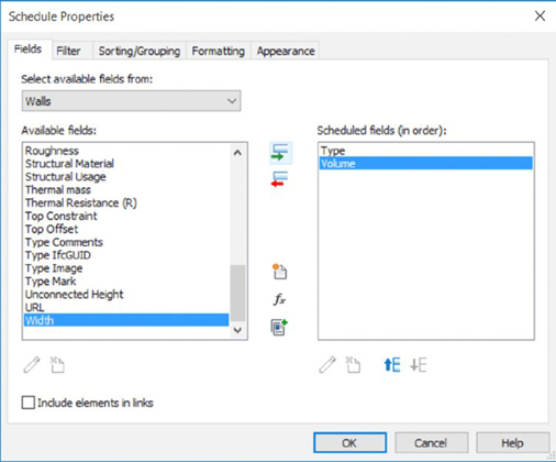
In the Schedule Properties dialog box, make sure you are in the Fields tab. Add the parameters Type and Volume to the Scheduled Fields list, as shown in Figure 10.79.
Click the Add Parameter button, and in the Parameter Properties dialog box set the following values:
Parameter Type: Project Parameter
Name: Demo Cost Per Unit
Type Or Instance: Type
Type Of Parameter: Currency
Group Parameter Under: Construction
Click OK to close the Parameter Properties dialog box, and then click the Calculated Value button in the Schedule Properties dialog box. Create a new calculated value with the following values. You’ll need to add a calculated value in order to multiply the demolished walls’ volume by the cost per unit and get the total. Click the Calculated Value button in the Schedule Properties dialog box. We’ve divided the Volume value by 1 CF to keep the units consistent.
Name: Disposal Cost
Formula or Percentage: Formula
Type: Currency
Formula: Volume / 1 CF × Demo Cost Per Unit
In this formula, it is important that the spelling of each parameter be exact because it is case sensitive. We divided by 1 unit (cubic feet in this example) to eliminate the volumetric units in the equation. The result will be a number that is multiplied by the value assigned to the Demo Cost Per Unit parameter.
Click OK to close the Calculated Value dialog box, and then switch to the Sorting/Grouping tab. Establish the settings to sort by Type (with the Header option) and then by Volume, as shown in Figure 10.80. Check the box for Grand Totals, and set the associated drop-down list to Totals Only. Deselect the Itemize Every Instance option.
Switch to the Formatting tab and select Disposal Cost. Check the Calculate Totals box, and then click OK to create the schedule.
In the Properties palette, set Phase to New Construction–Phase 1 and Phase Filter to Demo Only. After you type a value in any of the Demo Cost Per Unit fields, the schedule will look similar to the image in Figure 10.81.
For the Phase 2 demolition schedule, don’t start over. In the Project Browser, duplicate the previously created schedule and just change the phase in the Properties palette to New Construction − Phase 2.
Figure 10.79 Add Type and Volume to the list of scheduled fields.
Figure 10.80 Set the Sorting/Grouping options for the demolition schedule.
Figure 10.81 The completed wall demolition schedule
At this point in the exercise, you can drag the floor plan views, 3D views, and schedules from the Project Browser onto sheets for publishing, as shown in Figure 10.82. We’ll cover sheets in greater detail in Chapter 17, “Documenting Your Design,” but for now you can begin to become familiar with the process. Add the plans, 3D views, and schedule for Phase 1 to sheet A101, and then add the views for Phase 2 to sheet A102.
Figure 10.82 Multiple design views assembled on a sheet
Using the Design Option Tool
Everything looks great so far, but our client has asked us to prepare an alternative design for the second phase of construction. We’ll accomplish this within the same exercise file using the Design Option tool. Let’s get started with the following steps:
From the status bar at the bottom of the application window, click the Design Options icon. In the Design Options dialog box, click the New button to create a new option set. Click the Rename button and name the new set Phase 2 − Proposed. Click the other New button to add two options, as shown in Figure 10.83.
Activate the LEVEL 1 − PHASE 2 PROPOSED floor plan and then select all the new construction elements. Switch to the Manage tab in the ribbon, and click Add To Set. Uncheck Option 2, as shown in Figure 10.84, and click OK. This will add everything selected to the primary design option. If you changed the Phase Filter property to help select the new construction elements, remember to set it back to Show Previous + New.
In the Project Browser, duplicate LEVEL 1 − PHASE 2 PROPOSED and rename it LEVEL 1–PHASE 2 PROPOSED − OPTION 2.
This will be your working view for the second design option.
Open the Visibility/Graphic Overrides dialog box and switch to the Design Options tab. Change the Design Option value for the design option set shown from <Automatic> to Option 2. Click OK to close the dialog box.
From the Design Options toolbar, select Option 2 in the drop-down list to make Option 2 active for editing and create another design iteration, as shown in Figure 10.85. When you are finished with the alternate layout, set the Design Options drop-down list to Main Model.
In the Project Browser, duplicate the 3D view named PHASE 2 − PROPOSED and name the duplicated view PHASE 2 − PROPOSED − OPTION 2. In the Visibility/Graphic Overrides dialog box for the view, set Design Option to Option 2.
Activate sheet A102 and then drag and drop the views for Option 2 onto the sheet, as shown in Figure 10.86.
Figure 10.83 Create a new design option set with two options.
Figure 10.84 Add the primary design elements to only the first design option.
Figure 10.86 Place the alternate design option views on a sheet.
If you’d like to download the completed file used for this exercise, you can find it in the Chapter 10 folder at this book’s web page; the file is called c10-Exercise-Finished.rvt.
The Bottom Line
Use the Phasing tools to create, demolish, and propose a new design. Time is such an important element to the design process and nearly impossible to capture with traditional CAD tools. Don’t use phasing for construction sequencing (there’s a better way). Embrace phasing for communication, not just illustration.
Master It How can you use phasing to communicate your design across a series of key stages? What kind of project is best suited to phasing?
Understand and utilize groups. Groups are great for creating collections of both host and family component geometry. Just remember to apply best practices, and you’ll avoid a lot of common roadblocks. Individual model elements within groups will always appear properly in schedules, as you’d expect. And creating exceptions in groups allows you to make subtle changes without creating a new group.
Master It Why shouldn’t you mirror groups?
Create and use design options. Like groups, design options work great when you follow the rules. Design options are intended for design iteration that is bounded and well-defined—not for putting multiple buildings in one project file. Remember that links, groups, and phasing can exist within design options. Always keep hosted elements with their host when using design options.
Master It Suppose you have a multistory tower. How could you show multiple design options for the entire vertical exterior enclosure?