
5
Real Time Control: Interrupts
Chapter Outline
- Learn the hardware and software interrupts, interrupt vectors, service routine address generation, source identification flags and polling of sources in a microcontrollers MCUs
- Learn various MCU interrupt-handling structure features
- Learn uses of masking by selectively enabling the interrupt servicing
- Learn the 8051 interrupt structure handling codes and feasibility of coding an ISR within 8 bytes available at a vector address for an interrupt source or source group by examples of simple programs
- Learn interrupt applications and examples and programming examples in assembly and C
A child can first learn multiplication examples of one-digit numbers and can then learn the effects of multiplications. Then he or she can be taught multiplication tables of the other numbers and the multiplication process for 2, 3 and more digit numbers. Another alternative is to memorize the multiplication tables of the numbers and then learn the multiplication of single-digit, two-digit and three-digit numbers.
The first approach is being followed in the book. Chapter 4 describes individual instructions in the 8051 instruction set. This chapter gives examples of instructions, C statements, simple programs and interrupt service routines (ISRs) related to interrupts. A programming framework for programming using assemblers and C compilers will be described in Chapter 9.
We have already studied the following:
- Sources of interrupt in 8051 family MCU
- Unmasking and masking of interrupt sources for service using bits in the interrupt enable (IE) register
- Priority assignments for service using the bits in interrupt priority (IP) register
- Vector addresses for the ISRs of the sources of interrupt in 8051
- Simple instructions related to interrupts
A precise and thorough understanding of the interrupt structure in 8051 and other MCU families has, however, not been dealt so far, although it is a matter of great importance for smart use and for the realization of full potential of any MCU.
The interrupt structure allows us to employ an MCU for real-time control of multiple tasks. It lets us achieve the real-time use and facilitates synchronization of the devices and resources.
This chapter enables a reader to understand the interrupt structure of different MCUs. It gives examples of how to write the programs in many important applications and of real-time interrupt latency control applications.
5.1 INTERRUPT APPLICATION EXAMPLES
When a mobile phone rings and interrupts us, we immediately respond to it by setting aside whatever work we are involved in. There could be an important message awaiting us.
We respond to the phone call by pressing its key. This interrupts the presently executing instructions in the mobile. A service routine executes in the mobile on interruption by pressing the key. Similarly a service routine executes on interruption from another source.
A device such as a timer interrupts the processor’s presently running program. When a timer overflows, there is an interrupt. When a timer reaches a pre-fixed count or time, there may be an interrupt. When the timer receives an input in order to capture the instance of occurrence of an external event, there may be an interrupt. There may be periodic clock interrupts from a timer. The serial interface on serial input causes an interrupt. Serial interface on serial output interrupts when the transmit register becomes empty.
An error that occurs when a program runs or an input from an external event also causes an interrupt. A number of sources can interrupt the central processing unit’s (CPU) current program.
There are a number of sources of interrupt of a running program. Just as the interruption from the phone is important to us, the interrupts from the events from various sources are important to any MCU-based system.
Interrupt-handling structures in the CPUs and MCUs are used for a number of applications. A few examples of applications are as follows:
- Real-time control using timers. Chapter 6 covers the use of timers in a number of applications.
- Actions on (i) pulse accumulator input edge and (ii) overflow for the pulse width modulation. [PWM is needed for digital to analog conversion]
- Serial transmission and serial reception of characters.
- An external circuit sends an interrupt to the MCU for seeking attention. An example is in an application circuit to count the number of rotations of a gear.
- Inputs from keyboard or mouse.
- Start and end of analog to digital conversion.
- Software interrupt instruction to handle exception conditions in a program such as division by 0, square root of a negative number and to signal execution of another service routine.
- Illegal opcode.
- Clock failure.
- Watchdog timer.
5.2 ROUTINE, INTERRUPT AND INTERRUPT SERVICE ROUTINE
5.2.1 Call to a Routine
A call is a program instruction for diversion from the program after executing the current instruction.
Let us assume that a program or routine is executing and running a set of instructions. The running instructions are called foreground program. A foreground program instruction may call another routine at some point of time using instruction (for example, ACALL or LCALL instruction of 8051). The call instruction executes as follows:
- Saves the program counter (PC). Both higher and lower bytes at PCH and PCL for the PC saves at the stack. The stack pointer (SP) re-adjusts the SP to SP′ = SP + 2.
- Gets the address of the called routine (using 16 bits after the first byte in case of the LCALL or the 11 lower bits at the instruction and 5 higher bits from 5 higher bits of PC of instruction after the current instruction in case of the ACALL) (refer Section 4.11.6.)
Return from a Routine
The return instruction (last instruction RET at the called routine) executes as follows: It restores the PC, both higher and lower bytes, at PCH and PCL from the stack top and re-adjusts the SP to SP = SP′ − 2.
Note that the CPU registers other than PCH and PCL also saves in certain MCUs on the call to a routine and restores on return. For example, 68HC11 saves the registers also. Figure 5.1(a) shows the steps in the call to a routine and return from the routine.
Nested Calls
A call after executing an instruction is a user-programmed diversion from the program’s current sequence of instructions in foreground program A to another sequence of instructions in another routine B. The B can also call another routine C at a certain point of time and that can call the third routine D and so on. The return from D is to that instruction of routine C, which needs execution on return from the called routine D. The return from C is to that instruction of routine B, which needs execution on return from the called routine C. The return from B is to that instruction of foreground program A, which needs execution on return from the called routine B. The calls from A to B, B to C and C to D are also referred to as the nested calls in this case. Nesting of calls means that a routine can also call another routine from within. Figure 5.1(b) shows the steps in the nested calls.
Interrupt
A foreground program instruction may be interrupted for calling the service of another routine at an unknown instance of time. A call to interrupt service routine (ISR) on hardware interrupt is not a programmed (not from the user instruction at the program) diversion. It occurs after executing the current instruction on an event from an interrupt source.
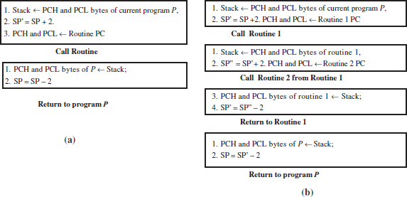
Figure 5.1 (a) Steps in the call to a routine and return from the routine and (b) steps in nested calls
Interrupt Source
An interrupt source is a source of an event at a device or circuit that causes the interrupt. For example, the ringing of a phone is an interrupt source for the mobile. The key that is pressed on the phone is the interrupt source for the mobile. A timer timeout is an interrupt source. It causes from event of setting timer overflow flag.
An interrupt source may also be a software interrupt instruction (SWI) for the interrupt. The SWI executes when some exceptional condition is encountered during the running of a program.
Interrupt Service Routine
Suppose, a certain value for the number of ticks required for the timeout is loaded into a timer, and the timer is started using certain instruction. On starting, it starts accepting the clock inputs at regular intervals. An overflow of the timer represents its timeout. On a timeout-event, some action is required. The action on that event is called the timer overflow interrupt. The foreground program currently executed by the CPU can get the timer overflow interrupt at any instruction (at any point of time). On the timer overflow, interrupt of the ongoing program occurs after completing the instruction being executed. On the interrupt, the execution of instructions starts for a service routine. The new routine is called interrupt service routine (ISR).
An ISR is a routine that executes because of the interrupt (service demand) from a source.
An ISR executes on a hardware signal or software interrupt (also called exception or trap). The foreground program A diversion is from the current sequence of instructions in A to another sequence of instructions B, which services the interrupt. The sequence of these codes B is called interrupt service routine.
The ISR B may be required to first push the parameters of A in case the ISR is likely to change these during execution. A byte at an addressed location or register (other than the bytes at the PC) may also be saved by push. A push is on to the stack. Push can be of the Processor Status Word, accumulator, other special function registers or memory addresses that are likely to be affected by ISR instructions.
There are certain features in 8051, which most often makes it possible to have a short ISR and does not need the PUSH and POP instructions at the ISR start and before return from the interrupt.
Note that in certain MCUs on the interrupt call to a routine, the CPU registers other than PCH and PCL also save and therefore they also restore on the return. For example, 68HC11 restores the registers also.
Before the Return Instruction in ISR
All saved parameters and any byte at an addressed location or register (other than the bytes at the PC) pushed at the beginning must be popped in reverse order (last in first out; LIFO) before the return. ISR B must restore in the LIFO way, the saved parameters by the pops from the stack. The byte of an addressed location or register (other than the bytes at the PC) that was saved on the stack within the ISR must be restored by the ISR before the RETI instruction. These actions restore all the previous states of the variables and flags in the registers so that the foreground program functioning is not affected.
Return Instruction in ISR
The return instruction RETI (last instruction at the ISR) at the ISR B is executed as follows:
- Restores the PC (all upper and lower bytes at PCH and PCL) at the stack and re-adjusts the SP.
- Restores the interrupt structure and makes it identical to the one before the interrupt and service of the ISR.
- Checks another pending interrupt service(s). If yes, initiate another servicing action(s).
- If no, start executing the foreground A or the routine left earlier on the interrupt.
Suppose the PCL was saved first on the stack top, then the PCH. On return, first the PCH retrieves from the stack top and then the PCL. It means LIFO. Figure 5.2 shows the steps for an interrupt to a service routine and return from that.
The RETI is an instruction in 8051 for return from the ISR. It restores PC of the foreground program. It is similar to the RET instruction in a called routine. The additional difference is that the interrupt-handling structure resets and gets ready for the next ISR and next interrupt.

Figure 5.2 Steps for an interrupt to run a service routine and steps for return
5.3 INTERRUPT-HANDLING STRUCTURE OF AN MCU
The following steps are adopted for handling an interrupt in 8051 MCU:
- The first step is to find the interrupt occurrence of an interrupt, which is done for example by finding whether the identification flag for that interrupt is set.
- The second step is to find whether that interrupt is masked or unmasked.
- The third step is to get the address of the service routine if not masked.
- The fourth step is context switch by saving the PC of the interrupted program and loading the PC for the new ISR for executing the ISR.
- The last step is to return from the interrupt on RTI instruction and restore PC bytes that were saved earlier on the stack.
Figure 5.3 shows different elements of an MCU interrupt-handling structure.
Interrupt-handling structure provides for the following:
- Enabling (unmasking) or disabling (masking) of the service to the sources. Also, at any given instance, the needed ones can be enabled (unmasked) and the remaining ones masked (refer-Figure 3.18 and Table 3.19).

Figure 5.3 Different elements of an MCU interrupt-handling structure
- Priority assignments, default assignments, increasing or lowering priorities as per need [refer Table 3.19].
- Identification mechanism for the interrupt source and the resetting mechanism for identification flags. Resetting is by hardware or software.
- Finding or generating the address of the ISR address where the CPU vectors for the service and the processor executes the ISR at that distinct address for a distinct source (or source group; Refer Figure 3.19 and Table 3.20).
5.3.1 IDENTIFICATION OF AN INTERRUPT SOURCE
A source activates the interrupt-handling (servicing) structure on identification. A flag facilitates the identification of an event in the processor when an internal interrupt source is activated. A flag can be either at a register called interrupt status register or at the interrupt pending register or may coexist with the control bits in the control register. Examples of co-existence are in TCON and SCON registers in 8051. Table 5.1 gives the example of identification flags for the interrupt sources in 8051, instances of their setting to 1 and instance of their resetting to 0. Setting to 1 indicates the need for the interrupt handling, and then the interrupt-handling structure activates in case that interrupt is not masked. INT0 or INT1 level-activated interrupts do not change (latch 1) in IE0 or IE1 and thus do not have identification flags.
Table 5.1 Example of identification flags in 8051 and their setting and resetting

5.3.2 RESETTING OF INTERRUPT IDENTIFICATION FLAGS
Table 5.1 also gives the instance of its resetting to prevent repetition of interrupt service from the same event for the occurrence of interrupt in 8051. Resetting for timer overflow and edge-triggered interrupts is by the hardware automatically on execution of ISRs. Resetting for TI and RI interrupts are by software (instructions in the ISR for servicing those) and are not automatically on start of execution of ISR.
Example 5.1
Figure 5.4(a) shows the example of occurrences of timer overflow TF0 and serial receive receiver interrupt (RI) at two instances. Timer overflow TF0 flag resets on start of ISR for it. However, for RI and TI, resetting must be done by an instruction before RETI and after the start of ISR to enable the next interrupt from the serial port.

Figure 5.4 (a) Example of occurrences of timer overflow TF0 and serial receive RI interrupt at two instances, (b) example of occurrences of repeated serial receive RI interrupts from the serial bits arriving at the RxD and (c) example of occurrences of repeated 1 to 0 edge transitions at INT0 input pin when counting the number of rotations of a wheel. The identification flag whether automatic or not on the ISR start settings is also shown in these figures
Figure 5.4(b) shows the example of occurrence of repeated serial RIs from the serial bits arriving at the R×D.
Example 5.3
Assume that a wheel is rotating. There is a photo-transistor PT and LED pair. The LED passes light through the wheel when the wheel completes one rotation. Thus, a PT starts conducting when the rotating wheel passes through 360°−2° angle of rotation and the LED is able to send light to it. It stops conducting when the rotating wheel passes +2° past one rotation. A pulse is thus generated at INT0 if this pin connects the PT. Figure 5.4(c) shows an example of occurrences of repeated INT0 inputs, for example, when counting the number of rotations of a wheel. Each wheel rotation brings a photo-transistor into a conducting state from the light. The identification of flag settings is also shown in these figures.
Example 5.4
Assume that a key sets 1 when released and when pressed resets to 0 the INT pin INT0 or INT1. When IT0 or IT1 = 0, then the interrupt is of a level-activated type. The pin level-0 activated interrupts do not change (latch 1) the IE0 or IE1. Figure 5.5 shows the timing diagram for the example of occurrences of repeated level-activated case ISR execution when INT0 input is kept 0 for long periods. Long means time interval greater than execution interval of the ISR. ISR repeat execution is prevented when either enable flag for INT0 or INT1 is made 0 or the level is made 1 from 0 at the INT0 or INT1 pin.
5.3.3 ADDRESS OF INTERRUPT SERVICE ROUTINE
Consider that a CPU has been enabled to respond to an interrupt from a source. A call is then to be made on an ISR. Let the first instruction address of the ISR be ISR_ADDR. How does the CPU find or evaluate the ISR_ADDR? That is, how is step 4 (Figure 5.2) of the four steps pointed out above implemented before the diversion to the ISR? Table 5.2 gives three methods for an interrupt source or source group:
- Direct address access method for an interrupt.
- Vector address method for the ISR address for an interrupt source or source group.
- Vector address for the ISR pointer method for obtaining the ISR address pointer.

Figure 5.5 Example of occurrences of repeated ISR run when the INT0 input is kept at level 0 for long periods using a switch

Figure 5.6 (a) Direct address access method for an interrupt, (b) example of vector address for the ISR address for an interrupt source or source group and (c) example for vector address for the ISR address pointer for an interrupt source or source group
Figures 5.6(a), (b) and (c) show the steps in three methods.
Vector address ISR_VECTADDR
ISR vector address is a memory address where the CPU PC vectors (program flow changes the direction) automatically for the execution of ISR.
An action on interrupt from a source can occur only whenever the CPU has been previously enabled by the program (or internally by the CPU itself) to respond to that interrupt.
Table 5.2 Method of finding ISR address for an interrupting source or source group

a In 8086, an ISR_VECTADDR_Pointer is indirectly calculated. The external device just needs to put a byte for the type (level) of the interrupt in the second interrupt acknowledgement cycle. [Level means priority level in order of decreasing priority of 8086 CPU for interrupt service.]
Example 5.5
- The timer 0 overflow interrupt vector address is 0x000B and the ISR codes are at 8 bytes assigned between 0x000B and 0x0012 (refer Figure 3.19 and Table 3.20).
- 8051 processor vectors to the ISR at 0x0023 for distinct source group. The group consists of UART serial receiver and transmitter (refer Figure 3.19 and Table 3.20) interrupts.
Advantage ofvector address for the ISR address itself: The vector addresses of the multiple interrupts can separate by 8 bytes or more. The 8 bytes can suffice for a short ISR piece of code. For example, when the successive characters of a string are to be sent on the TxD line from SBUF in 8051, the 8-byte space suffices (Program Example in Section 5.9).
Example 5.6
The 8051-interrupt structure generates a vector address for the corresponding source ISR. The ISR can be a maximum of 8 bytes, which can be located at the vector address or from where a call can be made to the longer piece of codes from there.
Advantage ofvector address for the ISR address pointer: The vector addresses of the multiple interrupts can be very near each other, separated by 2 or 4 bytes.
Example 5.7
8086, the vector addresses start from 0x0000 and each one is separated by 4 bytes only. The vector addresses for the ISR pointers are 0x0000, 0x0004, 0x0008, 0x000C, …, 0x00FC for type 0, type 1, type 2, type 3, …, type 255 interrupts. There can be 256 interrupt types (levels) of the interrupts. Two bytes at each address give 16 bits for the IP (instruction pointer 16-bits) and the next 2 bytes give 16 bits for the CS (code segment 16-bits) needed for calculating the 20-bit ISR address in 8086. Instruction physical address = (CS) × 10000H + (IP).
The 8086-interrupt structure generates a vector address for the corresponding source ISR pointer. The ISR can be at a physical address, pointed by the segment and instruction pointer defined at the 4 bytes located at the vector address. Successive interrupt levels and, therefore, vector addresses are separated by 4 bytes and there are a total of 256 levels of interrupts.
Example 5.8
The 68HC11/12 family interrupt structure generates a vector address for the corresponding source ISR pointer. Successive vector addresses are separated by 2 bytes.
The UART serial port interrupt for the receiver and the transmitter has a vector address of ISR_ VECTADDR_Pointer = 0xFFD6-0xFFD7 for finding the higher and lower bytes of ISR. The PC loads these bytes for executing the ISR for the serial port interrupt.
5.4 INTERRUPT LATENCY AND INTERRUPT DEADLINE
Interrupt latency can be defined as the interval between the interrupt event and the start of the interrupt service for that event. For example, if a timer has overflowed at an instance t0 and its service routine initiates at time t1, then the latency interval for it equals Tlat = (t1−t0) (refer Sections 5.6 and 6.3.1 for further description). Let the timer overflow interrupt be serviced latest by t2, then the deadline Td = (t2 − t0). Interrupt deadline means interrupt service deadline. It is defined as maximum permissible interrupt latency plus execution interval of the ISR.
Example 5.9
- Assume that an array of 10 telephone digits is being received in ASCII code form in 1 s. Figure 5.4(b) shows an example of occurrences of the repeated serial receiver RI interrupts from serial bits arriving at RxD. The deadline for the interrupt on receiving each digit = 0.1 s.
- Assume that a wheel is rotating. On completing each rotation, there is a pulse of 1 and 0, which is repeated 10 times in 1 s, which is equal to the number of rotations of a wheel in 1 s. Figure 5.4(c) shows an example of occurrences of repeated edge-triggered INT0 inputs; for example, when counting the number of rotations of a wheel. The deadline for successive ISR-INT0 is 0.1 s.
Example 5.10
Figure 5.4(a) shows the example of occurrences of timer overflow TF0 and serial receive RI at two instances. If the time difference between these two instances is 100 μs.
- What are the deadlines for T1 and RI if the next interrupt is expected to be after 20 μs after the RI? Assume that the time taken to the context switch is 2 μs and the time taken to execute ISR for T0 is 8 μs.
- What can be the maximum possible latency for ISR-T0? (The context switch is the time to save the registers on the stack top or restore the next routine registers from the stack top.)
Solution:
- The deadline for finishing the RI interrupt = 20 μs because after RI, the next interrupt is after 20 μs. The deadline for ISR-T0 is 100 μs because the next interrupt is after 100 μs.
- After T0 overflow interrupt, 2 μs is the time to the context switch to the corresponding ISR-T0. ISR-T0 takes 8 μs to execute and 2 μs to the context switch to ISR-RI. The maximum possible latency for T0 is 100 μs − 12 μs = 88 μs, as T0 takes 12 μs to execute and the context switch to RI and RI occurs after 100 μs from T0 interrupt.
Example 5.11
Assume that the mode 3 (11-bit UART) serial interrupt is receiving the bits at 9,600 baud/s. The repeated interrupts (Figure 5.4(b)) are therefore occurring at every 11/9,600 s. Therefore, the deadline for servicing each interrupt, Td = 11/9,600 s. Therefore, the latency for the serial port SI interrupt should be less than 11/9,600 s. Td < Tlat is the requirement, and priority assignments have to be according to this, else a service to an event is missed. If ISR for serial buffer takes 8 μs, the latency = 11/9,600 second − 8 μs = 1,145.83 − 8 μs = 1,137.83 μs.
Example 5.12
Assume that 80196 MCU provides for a FIFO in place of a serial receive-buffer for just 1 byte. It provides three interrupts, I1 when the first byte is in the buffer, I2 when FIFO is half full and I3 when FIFO is full. Assume that bytes are received every 11/9600s.
- What is the deadline for the serial interrupt if I2 is used in place of I1 to receive bytes?
When I2 is used, 4 bytes make FIFO half full before the next interrupt. Time is still there for 4 more bytes to be received. Hence, the deadline = 44/9,600 s.
- What is the deadline for the serial interrupt if I1 is used to receive bytes?
When I1 is used, I1 must be serviced before the next serial byte get into the buffer. The deadline = 11/9,600 s.
- What is the deadline for the serial interrupt service if I3 is used to receive the bytes?
When I3 is used, 8 bytes make FIFO full before the next interrupt. Time is still there for 8 more bytes to be received after the first byte is received. Hence, the deadline = 88/9,600 s.
The use of I3 provides high deadline period for servicing serial interrupts.
5.5 MULTIPLE SOURCES OF THE INTERRUPTS
An MCU has a number of devices and a device may have multiple functions. There are, thus, multiple sources of the interrupts to a program being executed by the CPU of an MCU. Figure 3.18 shows the multiple sources of the interrupt. For example, refer timer interrupt and SI (Serial Port Interface) 8051 interrupt sources.
A source can be either internal or external. For example, INT0 is an external interrupt and T0 overflow is an internal interrupt source in 8051. Each of the interrupt sources demands a temporary transfer of control from the presently executed program to an ISR corresponding to the source (or source group). The internal sources differ in different CPUs or microcontrollers. Ways of external sources interrupt could also differ. The important internal and external interrupt sources are described as follows:
5.6 HARDWARE INTERRUPTS RELATED TO INTERNAL DEVICES:
- An MCU has the interrupts from the internal timer overflows (timeouts).
- An MCU can have the input capture interrupt(s) (8052 and 68HC11/12.). The input capture interrupt occurs when the timer count at that instance is captured in a register when an input or an event occurs.
- An MCU can have the out-compare interrupt(s) (68HC11/12.). An out-compare interrupt occurs when the timer count at that instance equals to a preset time in a compare register.
- An MCU can interrupt on (i) the end of a serial transmission of a character (serial transmitterbuffer empty) and (ii) the end of the serial reception of a character (serial receive buffer full) (Examples: 8051, 68HC11/12 and 80196).
- An MCU (example, 80196) can also interrupt when a serial receive buffer (8 bytes FIFO) is half full or full.
- An MCU can interrupt on (i) the start of an analog to digital conversion and (ii) at the end of the conversion.
Hardware interrupts related to external sources or peripherals: At an external pin, on either occurrence of a level 1 or 0, or a positive or negative edge transition, an interrupt may be caused. It depends on the CPU. Table 5.3 gives the examples of hardware-related external interrupts.
Table 5.3 Examples of external pin interrupts and methods of finding their vector addresses
| Method of Finding the Address | Example |
|---|---|
Direct address access |
There is an interrupt pin, for example, in 80×86. It is INTR. The external circuit, which interrupts, also sends the interrupt type or the level on the data bus. It does so in the second INTA cycle at the INTA pin for the interrupt acknowledgement to the circuit. (This pin is not present in 8051 family MCUs.) |
Vector address as the ISR address |
When the external circuit interrupts at this pin, the CPU hardware generates the vector address internally. The examples of these pins are RST5.5, RST6.5 and RST7.5 pins in 8085, where the vector address generated internally = (5.5 or 6.5 or 7.5)×8. Note that this calculation of address formula uses the decimal numbers. INT0 and INT1 pin external interrupts are the examples in 8051 MCUs. |
Vector address for the ISR address pointer |
NMI pin in 80x86 is an example. The vector address, which generates, points to the 4 bytes for the bits to be loaded into the IP and CS registers, which then define the ISR_ADDR. The program then executes the ISR from the 20-bit address (IP) + (CS)×10000H. |
Software-related interrupts: Table 5.4 gives the examples of the software error-related interrupt.
Table 5.4 Examples of software-related interrupts
| Interrupt | Example |
|---|---|
Software instruction to enforce an interrupt |
a. ‘SWI’ instruction in 68HC11/12 family (refer Section 14.2.2(6)) or in ARM |
The software error-related interrupts in 80×86. Examples are the division by zero (type 0), illegal opcode (type 6) and overflow (type 4). |
aRefer Table 7.13 in Daniel Tabak, Advanced Microprocessors, McGraw-Hill, International Students Edition, 1995, pp. 145–147.
NON-MASKABLE INTERRUPT SOURCES
Certain interrupt sources cannot be masked (corresponding ISR cannot be disabled from execution) and these must be serviced (8051 has all interrupts that are maskable). Table 5.5 gives examples of non-maskable interrupts.
Table 5.5 Examples of non-maskable interrupts
| Processor Family | Example |
|---|---|
80×86 |
An example, NMI pin interrupt in 80x86. It usually connects to DRAM parity error detection circuit. A few of exceptions (traps) also need to be always serviced. |
68HC11/12 |
a. Clock monitor failure. The slow down in the clock must interrupt and execute the required instructions. |
5.7 ENABLING (UNMASKING) OR DISABLING OFTHE SOURCES
There are a number of devices and therefore multiple sources of interrupts. There are certain interrupts that can be masked, so those events are not responded by the interrupt-handling structure. Figure 3.18 shows the different maskable interrupts in 8051. Table 3.19 gives the interrupt enabling-disabling bits, IE.0 to IE.7 for these.
An MCU-based system may require the following during the execution of a foreground program or routine:
- Disable all interrupt sources to the running program using DI instruction for disabling all.
- Enable interrupt structure responses but masks certain specific source(s) or source group(s).
Example 5.13
- Consider IE.7 bit at the IE in Table 3.19. Clearing IE.7 bit to 0 disables all interrupt-event responses by the interrupt structure of 8051. IE.7 is therefore also called primary level enable bit.
- IE.6–IE.0 bits at the IE register in Table 3.19, which masks specific source(s) or source group(s). Setting IE.7 to 1 enables all interrupt-event responses by the interrupt structure of 8051 and clearing IE.4 ≡ 0 masks the serial port interface group of two interrupts—Receiver and transmitter interrupts. IE.4 is called the SI mask bit or secondary level enable bit.
CPU of MCU hardware may have one of the following two features:
- Some CPUs disabling all interrupts during the first instruction in ISR: Certain CPUs hardware disables all interrupts for the duration of the first instruction when an ISR is executed. This allows diversion to other higher priority ISRs from within an ISR after the first. This process is called pre-emption of the ISR.
- Some CPUs disabling all interrupts during the instructions of ISR: Certain CPUs hardware disables all interrupts for the duration of ISR instructions when an ISR is executed. This prevents diversion to other higher priority ISRs from within the ISR.
Nested Interrupts
Nested interrupts become feasible in case 1. An interrupt after executing an instruction is an event-triggered diversion from the program’s current sequence of instructions in foreground programA to another sequence of instructions in another ISR B. Assume that interrupt priorities are highest at D, highest but one C and lowest is B. B can therefore also interrupt to run the ISR C at a certain point of time and that can interrupt to run ISR D and so on. The return from D is to that instruction of ISR C, which needs execution on return from the D. The return from C is to that instruction of ISR B, which needs execution on return from the C. The return from B is to that instruction of foreground program A, which needs execution on return from the B. The interrupts from A to B, to C and to D are also referred to as the nested interrupts in this case. Nesting of interrupt means that a routine can also interrupt to another routine from within. Interrupt from in-between is also called preempting. Preemption is by a higher priority interrupt.
Figure 5.7(a) shows steps in the interrupt call to a routine (ISR) and return from the ISR in an interrupt-handling structure (hardware and software). Figure 5.7(b) shows nesting of ISRs in cases of pre-emption.
Critical Section Instructions
The operations using a global variable or shared variable or memory buffer are done by instructions called critical instructions. Critical instructions are the instructions which must execute first before program flow to other task. (Program flow changes by context switch to other task.)
Example 5.14
- Consider the codes for updating the time in hours, minutes, seconds and date in a set of shared variables. Time-date updating is a critical operation. Once the updating starts, unless all variables are updated, the time and date will remain unusable for display or other actions. The time and date are the shared variables between the display-routine and the update-routine.
- Consider the codes for sending the characters into the display buffer. (The display buffer is a memory block for writing characters, which are taken by the display controller for display. The controller refresh the display at periodic intervals.) Only one routine should write at one time into the buffer. Therefore, the routine for writing characters in a display buffer has a critical region, as the display buffer is a global memory buffer for many routines.
Handling critical section codes: All maskable interrupt sources can also be masked by a single enabling/disabling bit. This helps in the execution of a critical section in current routine.

Figure 5.7 (a) Steps in the interrupt call to a routine (ISR) and return from the ISR in an interrupt handling structure when in-between diversion is not permitted and (b) nesting of ISRs in cases of preemption (in-between diversion) permitted
One method of handling critical codes for the operations on shared or global variables is using the instruction for disabling interrupts before the start and for enabling interrupts before the end of the critical section codes.
5.8 POLLING TO DETERMINE THE INTERRUPT SOURCES AND ASSIGNMENT OF THE PRIORITIES AMONG THEM
Polling
Several interrupt events can occur in quick succession before an interrupt is serviced by the ISR. Sometimes a source group is handled by a common ISR. An interrupt-handling structure in the system may provide for a polling mechanism. For example, serial port input and output interrupts are serviced by a common ISR.
Polling means to check each interrupt source one by one using instructions and service source which interrupted. The service is by calling the corresponding interrupt service routine. Polling is done one by one using instructions. It is done by successively checking for each interrupt which one occured. The checking continues by polling for the occurrences of different interrupts. It is done by finding whether the identification flag for an interrupt is set or reset. Figure 5.8 shows the sequence of instructions for polling and finding the pending interrupts.

Alternative to Polling
Polling to check each interrupt source one by one and service that interrupts by calling the service routine can take time when there are many interrupts. Therefore, there are two alternatives.
The Alternative to polling is CPU using vectored interrupts mechanism. Vector address sequencing is as per the priority. When an interrupt occurs, if it is not masked, then the interrupt-handling structure hardware causes the processor to vector to an address to enable the servicing of that interrupt by executing the service routine for that interrupt.
When the alternative is vectored priority interrupt, if a higher priority interrupt occurs, and if it is not masked, then the interrupt-handling structure hardware causes the processor to vector to ISR address of higher priority interrupt. This enables the servicing of that interrupt by executing the service routine for that interrupt. After the return from the higher priority ISR, the preempted ISR starts and executes the remaining instructions.
Polling among Common Interrupts in a Source Group Service by a Common ISR
Sometimes a source group is handled by common ISR. For example, serial port input and output interrupts are serviced by a common ISR. Polling then means to check each interrupt source in the group one by one using instructions and service, which interrupt by calling the set of service routine instructions. Polling one by one using instructions is done successively only for the interrupts in the group. For example, finding which of the identification flags for the interrupts are set or which reset in the group. Figure 5.9 shows the sequences of instructions for polling and finding pending interrupts in a group of interrupts TI and RI.

Figure 5.9 Sequences of instructions for polling and finding pending interrupts in a group of interrupts TI and RI
Instances of Vectoring to Higher Precedence Interrupt
An interrupt is under servicing by a temporary diversion to an ISR, and at that instant, another interrupt occurs which should also be serviced as per precedence assigned by CPU for vectoring to that interrupt. Two possibilities exist—either the second is serviced only after the completion of the ISR in service of the first interrupt, or the second interrupt is to be serviced immediately (after finishing the current instruction), giving it precedence over the first. First case example is 68HC11/12 and second case example is 8051.
Figure 5.10 shows the vectoring instances in two distinct family MCUs. When and how does the vector priority service take place? Table 5.6 lists the various vector priority service methods in the different interrupt structures in the different family MCUs.
Table 5.6 Various vectored priority interrupt procedure methods in different interrupt structures in the different families of MCUs

a The critical set ofinstructions, interrupt structure disabled at the set start, for example, by IE.7 bit in 8051 reset to 0 and enabled at the set end. For example, by IE.7 bit in 8051 set to 1.
b The priority is default priority, in case an IP register bit is not assigned ≡ 1. When IP register bits of two sources are equal, then the default priority prevails.
c Except for a specific interrupt source group special case XIRQ, which can be set to be polled at the end of each instruction in the presently executed ISR.
d 68HC11/12 has the fixed priorities only with no user-assigned priority values. Only the XIRQ non-maskable interrupt has the highest priority and is polled for its occurrence at the end of each ISR or foreground program instruction.

Figure 5.10 Two vectored priority interrupt procedures for the interrupt source: (a) 8051 and (b) 68HC11/12
5.8.1 Advantage of Finding Pending Higher Priority Interrupt Sources at the End of Each Instruction
A higher priority ISR cannot pre-empt a lower priority interrupt under execution in this case. We can define the priorities according to the earliest deadline, and a higher priority ISR can pre-empt a lower priority interrupt provided that interrupt source is not masked at the interrupt instance. The latency for the higher priority interrupt is minimized. However, the current service will have increased servicing interval and can miss the deadline. Therefore, ISRs should be made short.
Example 5.15
Assume that there are four interrupts, 1, 2, 3 and 4 in priority order (highest priority assignment is for 1 and lowest to interrupt 4). Let interrupt 3 be under service and have an execution time of 2 ms still left for return at an instant t. Interrupt 4 is pending at t since 1 ms. Now, a higher priority interrupt 1 pre-empts interrupt 3 at t. Let its execution time be 5 ms. Now, the latency for interrupt 4 becomes 1 + 5 + 2 = 8 ms. The latency for interrupt 1 is 0 ms as it gets services just after t. (Neglecting the time for context switching like saving the PC and registers.) Figure 5.11 shows the latency interval extension because of preemption. Interrupt 3 will now restart the service after 5 ms and will take 7 ms more to finish. If we have a user-assigned priority provision, whenever the pre-emption by the higher priority task has an adverse effect on the current ISR, it can be controlled.
5.8.2 Advantage of Finding by Interrupt Hardware for Pending Higher Priority Interrupt Sources at the End of an ISR
A higher priority ISR cannot preempt a lower priority interrupt under service in this case.
If the interrupt source is not masked at the interrupt instance at the end of the ISR, then the higher priority interrupt source will be executed. The latency for the higher priority interrupt thus equals the time left for finishing the current ISR. The lower priority interrupt services will have an increase in the latency interval by an interval equal to the execution time of the interrupt service. We can define the masks keeping in view the default priorities so that ISR execution is according to the first earliest deadline in case we have to lower the latency of the low priority interrupt.

Figure 5.11 (a)Assumed priority order and (b) the execution interval extension of the current ISR due to preemption at t the end of an instruction in the ISR (example of MCU 8051) and the effect of masking ISR-1 on interrupt 4 latency
Example 5.16
There are four interrupts, 1, 2, 3 and 4 in priority order (the highest priority assignment is for 1 and the lowest to interrupt 4). Let interrupt 3 be under service for 8 ms and have an execution time of 2 ms still left for return at an instant t. Interrupt 4 is pending at t since 1 ms. Now, once ISR 3 starts a higher priority interrupt 1 cannot pre-empt interrupt 3 at t, but only after the return from interrupt 3. Assume its execution time is 5 ms. Now, once ISR-3 starts the latency for interrupt 1 becomes 10 ms (neglecting the time for context switching by saving PC and registers). Figure 5.12 shows the latency interval extension because of pre-emption only at the end of an ISR. A started ISR is executed until the end (return instruction RETI), and the maximum latency interval of each service is therefore predictable. Note that if interrupt source 1 is masked, then the latency for interrupt 4 will become 3 ms only. Interrupt 3 will take only 2 ms to finish, which is the same as without the occurrence of interrupt 1 in between. Before the return from interrupt 4, interrupt 1 is unmasked. Interrupt 1 minimum latency is now 10 ms plus time taking in execution of ISR-4.
We can get an equivalency between the above two approaches using appropriate SWIs so that the earlier deadline ISR starts within the permitted latency.
Example 5.17
The first case (Section 5.6.3) becomes identical to the case (Section 5.6.4) if (i) all interrupts are disabled at the start of an ISR by DI instruction and (ii) enabled before RETI by another EI instruction. Alternatively, the user temporarily assigns the current ISR as priority 1 and others 0 before the start of an ISR.

Figure 5.12 (a) Assumed priority order and (b) the extension of latency interval of higher priority ISR due to preemption permission only at the end of the ISR (example of MCU 68HC11/12)
5.8.3 Default MCU-assigned Priorities
Let an MCU interrupt structure have the following features:
Each of the multiple-interrupt sources (including traps or exceptions) has a default-assigned priority on reset of MCU. Default MCU-assigned priorities at the interrupt structure set a structure in which the priority can be as per the requirement in most application needs in real time. For example, Table 3.20 shows that INT0 has the highest priority and UART the lower ones. The reason why serial interrupts are assigned low priority by default in the hardware is that these take place at a specific rate, for example, at every 11/9,600 s or 11/1,99,200 s for mode 3 SI interrupt and 9600 baud rate. The external interrupt at INT0 assigned the highest priority as it may be from some source, which demands immediate attention.
Example 5.18
8051 has default priorities assigned for seven or nine sources (Figure 3.19). The default internal assignments on reset in 8051 from Table 3.20 are as follows:
| Default Priority | Interrupt |
|---|---|
1 (Highest) |
INT0 |
4 |
TF0 |
5 |
INT1 |
6 |
TF1 |
7 |
TI and RI |
- 8096 default priorities are divided into eight maskable interrupt source groups.
- 68HC11 assigns the highest priority to the external reset pin, next to the failure of the clock, next to the watchdog timer, next to receiving illegal opcode in the instruction register and next to the external interrupt request XIRQ pin. The 68HC11 CPU assigns the lowest priority to the software interrupt instruction and the lowest but one to UART serial interrupts.
5.8.4 User-assigned Priorities
Certain MCUs provide for a user assigning the priorities by overriding the default-assigned priorities. Two notable features of user-assignable priorities are as follows—user-assigned priorities always override the default priorities and user-assigned priorities give a structure in which the priority can be increased or lowered as per the need in real time.
Example 5.20
- 8051 IP register has a user-assignable priority bit for each of the multiple-interrupt sources (1 or 0).
- Each of the multiple interrupt sources (including traps or exceptions) has a user-assignable priority value (between 0 and 31 or 256). An 80196 interrupt source can be assigned a priority value between 0 and 31.
Example 5.21
Give examples of when we assign the priorities.
Let the repeated serial buffer interrupts (Figure 5.4(b)) occur at every 11/9,600 s (assuming that the UART setting in SCON is in mode 3 and 9,600 baud.) If the byte is not received by servicing the RI interrupt every 11/9,600 s, the byte will be missed when the MCU starts servicing another program of more than 11/9,600 s. An A/D conversion interrupt can be assigned a lower priority in case only one measurement per second suffices. Let the signal from ECG (Electro-cardiogram) be recorded using the A/D conversion. If the converted byte is not put in the memory and the timer count is not put in the buffer on the highest priority, the MCU will not be recording the ECG signal faithfully. A/D conversion interrupt has to then be assigned highest priority and other interrupt sources can wait.
Example 5.22
- How will you assign the highest priority to TI and RI interrupt sources?
- It is found that the interrupt from these sources remain masked. What could be the programming error?
- We assign priority 1 to TI and RI and to all others 0 at the IP register. Because all other interrupt sources have the higher default priority (Figure 3.18), we should assign them as 0 priority in the IP register and assign TI and RI interrupt priorities as 1, only then will TI and RI get the highest priority. The instruction MOV 0B8H, #10H will make TI and RI serial UART interrupts priority the highest. The address of SFR IP is B8H (Table 3.19). Therefore, IP ≡ 00010000. IP.4 (PS bit) ≡ 1 and all other IP bits ≡ 0s. (Prefix 0 before B8 is as per the assembler mnemonics convention.)
- When we set EA = 1 and ES = 1, it enables interrupt-handling structure at a primary level and unmasks serial (SI) interrupts. The highest priority alone does not enable the interrupt service for a source or source group. If instructions do not set EA and ES to 1, then the priority allocation of TI and RI alone do not suffice.
5.9 INTERRUPT STRUCTURE IN INTEL 8051
5.9.1 The 8051 Family MCU Sources of Interrupt
The classic version of 8051 family MCU has the interrupt structure for two external interrupts, INT0 and INT1 (also INT2 in 8052) and internal interrupts from the timing and serial devices.
Timer Overflow (TF) Interrupts
Refer Table 3.11. TF1 and TF0 are flags for interrupt identification at TCON.7 and TCON.5, respectively, for the timer 1 and timer 0 overflows. TF1 or TF0 auto resets to 0 on executing the ISR instructions (Figure 5.4(a)). Resetting the flag to 0 enables the next instance execution of the ISR on the next overflow.
RI (Receiver Interrupts and TI (Transmitter Interrupts)
Refer Table 3.11. TF1 and TF0 are flags for interrupt identification at SCON.1 and SCON.0, respectively, for the serial port output and input. Flag TI or RI becomes 1 on completion of the serial output or serial input, respectively. They need resetting to 0 by the ISR instructions as they do not auto reset to 0 on executing ISRs. Resetting the flag to 0 enables the next execution of the ISR on the next serial output or input.
Edge-triggered Interrupts INT0 and INT1
Refer Table 3.11. IE1 or IE0 at TCON.3 and TCON.1, respectively, is INT1 or INT0 interrupt negative edge event identification flag when IT1 or IT0 = 1, respectively. The IE0 or IE 1 flag is latched (becomes 1) on occurrence of edge-triggered interrupt. RETI restores the interrupt event flag. The flag therefore auto resets to 0 on executing the ISR (Figure 5.4(c)). Resetting the flag to 0 enables the next execution of the ISR on the next negative edge at INT 1 or INT0.
Level-0 activated Interrupts INT0 and INT1
The IE0 or IE 1 flags are not latched (do not become 1) on occurrences of level-activated interrupts. RETI does not affect interrupt event flags. If we wish to avoid repeat execution of the ISR then before the RTI, either interrupt INT 0 or INT1 causing source should make the interrupting pin = 1 or DI disable interrupt should disable the corresponding IE bit for EX0 or EX1 bit in the IE register in case of a level-triggered interrupt on INT0 or INT1 pin.
Synchronous Serial RI (Receiver Interrupts) and TI (Transmitter Interrupts) Separate in Certain Versions
Serial port mode 0 interrupt flags TI and RI and becomes 1 on completion of the shift of the last bit out of 8-bits serial output and serial input, respectively. They need resetting to 0 by the ISR instructions. This prevents a repeat execution of the ISR. The next serial input or output can then be serviced by the ISR execution again.
5.9.2 The 8051 Family MCU Interrupt Source Groups and Default Priorities for Vectored Priority Interrupts
We find that most groups have one interrupt source, and for each group there is a vectored priority interrupt structure in 8051.
The default-assigned priority-wise source groups are as follows (higher priority ones are described first):
- Group 1—INT0 (external) interrupt IE0 only and it has a vector address, 0x0003. In the IP register, priority can be defined as high or low by PX0 bit. The 0th bit in the IE enables IE0 interrupt. If IE.7 EA bit = 1 and IE.0 bit is 1, then the IE0 interrupt is identified on IE0 = 1 on the occurrence (i) of a negative edge provided the bit IT0 at the TCON SFR is set or (ii) occurrence of a level 0 at INT0 pin if the bit IT0 is reset. There is the primary-level mask or enable as the 7th bit of the IE, IE.7. This source, therefore, is maskable through the IE.7 and IE.0 bits.
- Group 2 (8052 only) — The external T2EX pin negative edge interrupt, INT2, the timer 2 overflow, TF2 and EXF2 have a common vector address, 0x002B. Its user-defined priority can be defined high or low by the bit PT2 at the IP SFR (IP.5). TF2 identifies by the setting to 1 of timer 2 overflow flag. It can be made 0 by a writing a software instruction. EXF2 identifies a capture or reload of timer 2 on a negative edge at EXF2 pin, provided EXEN2 bit is set. EXF2 = 1 on the interrupt occurrence. It is reset to 0 by writing a software instruction. CP/ RL 2 bit when set, the T2 count capture will occur on T2EX pin event and if reset, an auto reload of timer 2 will occur on either timer 2 overflow or on negative edge at T2EX pin. ISR at the common vector address first identifies the source among the group 2 sources and then one by one services all the identified sources.
- Group 3 (in select family members)—The SI device serial synchronous port interface has a vector address, 0x0053. This is a lone source in the group. The PS1 bit defines high or low priority as per the bit, PS1 (IP.6 in IP SFR). When EA = 1 and if this bit is 1 then an SI interrupt can happen on the occurrence of the first bit. The first bit interrupt enables a read of the address of the slave using the serial clock and data lines. The occurrence of this interrupt is identified by 1 at the 7th bit in the SIINT register. This bit when set does not clear automatically on start of the interrupt service.
- Group 4—The timer 0 overflow is identified by the TF0 and has a vector address, 0x000B. The PT0 (IP. 1 bit) defines the priority, which can be high or low. When EA =1 and IE.1 = 1, timer 0 overflow TF0 bit sets 1 on the overflow event and automatically resets to 0 on start of the servicing of this interrupt source.
- Group 5—INT1 (external) interrupt IE1 has a vector address, 0x0013. In the IP register, priority can be defined high or low by the PX1 bit. The second bit in the IE enables the IE1 interrupt. If IE.7 EA bit ≡ 1 and IE.2 bit is 1 then the IE1 interrupt is identified on (a) after IE.1 = 1 on occurrence of a negative edge when bit IT1 at the TCON SFR is set and (b) occurrence of a level 0 at INT1 pin if the bit IT1 is reset. There is the primary-level mask or enable as the 7th bit of the IE, IE.7. This source is maskable through the IE.7 and IE.2 bits.
- Group 6—The timer 1 overflow identified by TF1 has a vector address, 0x001B. Its priority can be defined as high or low using PT1 (IP.3) at the IP SFR. If IE.7 =1 and IE.3 = 1, then when the timer 1 overflow event occurs, the TF1 is set to 1. It auto resets on start of the servicing of this interrupt source.
- Group 7—The SI serial port synchronous and asynchronous UART communication interrupts, TI and RI, are in this group. When the interrupt is enabled (EA = 1 and ES =1), the transmit data to be completed are identified by the TI. When the interrupt is enabled, the receive data completion event is identified by the RI. PS bit (IP.4 at the IP SFR) defines the priority that can be defined as high or low. The baud rate is programmed by T1 overflow intervals or T2 overflow intervals. TI interrupt event occurs on completion of the 8th bit serial transmission in mode 0. It occurs when the event is that the stop bit is to be transmitted in mode 1, 2 or 3. An SI interrupt is requested when an identification flag TI sets, that is, 1. When EA = 1 and ES =1, the RI interrupt event occurs on completion of the 8th bit and the last serial reception in mode 0. It occurs when the stop bit is halfway through during receiving in mode 1 or 2 or 3. ISR at the common vector address first identifies the source among the TI and RI and then one by one services the identified source(s) at the group. After the processor vectors to ISR, polling is done for TI and RI.
5.9.3 Unmasking and Masking of an Interrupt Source
Just as we ignore the ringing of our mobile phone by keeping the phone in the silent mode, there is an interrupt-handling mechanism for the unmasking and masking of an interrupt source. Meanings of unmasking and masking are the enabling and disabling of recognition of an interrupt from a source for a service. Service means the execution of a set of instructions called the ISR (refer Table 3.19). The mechanism uses the bits at the IE register at the SFR space within 8051 at the following addresses for the byte (Column 3) and addresses for the bits (Column 4).

5.9.4 Default Priority Assignments for Service
Refer Table 3.20. The default priority assignments are as follows:
| Default Priority | ISR |
|---|---|
1 (Highest) |
External interrupt at pin INT0 |
2 |
Timer T0 overflow interrupt |
3 |
External interrupt at pin INT1 |
4 |
Timer T1 overflow interrupt |
5 |
Serial UART interface interrupt and serial synchronous SI mode interrupt (available in classic variants) |
6 |
Interrupt vector address timer T2 overflow cum T2EX pin negative transition for the time capture or reload at T2 |
7 |
Serial synchronous SI mode interrupt (available in a few family variants) |
5.9.5 User Priority Assignments for Service
Just as we select priority in responding when there are multiple pending actions, the interrupt-handling mechanism also provides for the priority assignments for service in the case of multiple interrupts from the sources. The mechanism uses the bits at the IP register. The register is at the SFR space. The programmer can also use the default priority assignments, which the system assigns at the start (reset). Refer Table 3.19. The mechanism uses the bits at the IP register at the SFR space within 8051 at the following addresses for the byte (Column 3) and addresses for the bits (Column 4).

5.9.6 Vector Address for the Interrupt Service Routine
The interrupt-handling mechanism also uses a vector address for the ISR codes. There is an interrupt vector address corresponding to each interrupt source and group of sources. For example, 8051 has vector address = 0x0003 and ISR addresses between 0x0003 and 0x005A (refer Figure 3.18 and Table 3.20). It is reproduced below for ready reference.
| Addresses for ISR | Explanation of the Function |
|---|---|
0x0003-0A |
Interrupt vector address for external interrupt at pin INT0 |
0x000B-12 |
Timer T0 overflow interrupt vector address |
0x0013-1A |
Interrupt vector address for external interrupt at pin INT1 |
0x001B-22 |
Timer T1 overflow interrupt vector address |
0x0023-2A |
Serial UART interface interrupt vector address (common for TxD serial outputs and RxD serial input frames) |
0x002B-32 |
Interrupt vector address timer T2 overflow cum T2EX pin negative transition for the time capture or reload at T2 |
0x0053-5A |
Serial synchronous SI mode interrupt (available in a few family variants) |
5.9.7 Servicing of Interrupts in 8051
Default Conditions in 8051 on Reset
A noise-free input 1 for two machine cycles at the reset input causes the program to start from PC ≡ 0000H, (PCL ≡ 00H and PCL ≡ 00H). The special function registers, A, B, DPH, DPL, IE, PSW, SCON, TCON, TMOD, TH0, TL0, TH1, TL1, T2CON, TH2, TL2, RCAP2H, RCAP2L and T3 ≡ 00H. The IP, except its 7th bit, loads all bits to 0. User-assignable priorities are thus initially set to low, PCON bits except its 4th to 6th bit, as 0. The default SP ≡ 07H, WDCON ≡ A5H to disable the watchdog timer interrupts from T3 at the reset.
Interrupt Handling after Reset
A program in 8051 can be interrupted from the seven (or more in certain versions) permissible sources. This enables the uninterrupted execution of a set of instructions by disabling at the first instruction of the set and enabling at the last instruction of the set. When an interrupt occurs, the CPU in Intel 8051 does the following actions:
- Completes the current instruction. If the EA bit is 0 (IE.7, the bit 7 of the IE register, bit address is AFH) then it does not recognize any of the seven remaining IE bits, whether they are set for masking or for enabling a source. EA is also called the primary-level bit as it functions as an interrupt structure enabling bit. Therefore, the foreground program continues to be executed as before.
- When EA = 1 and the source which is unmasked (enabled) by setting an appropriate bit at the IE = 1, as per the priority by which the interrupt is to be serviced, the servicing of that source interrupt will occur and the following steps take place:
Step 1: The CPU pushes two CPU registers PCH and PCL on to the internal stack.
Step 2: Reset the EA = 0 momentarily (until the execution of the first instruction).
Step 3: The CPU sets the PC bits as per the corresponding ISR_VECTADDR, one among the seven vector addresses. ISR_VECTADDR is a vector address (Table 3.20). It is an address where the CPU PC vectors (program flow changes the direction) for the execution of the ISR after Step 2. A service program can either execute the routine or jump or call the ISR’s first instruction address if the ISR’s length is longer than 8 bytes and the routine executes from there.
Step 4: Set EA again to = 1 automatically at the ISR on execution of the first instruction. This enables the interrupt service from interrupts of priority higher than the present one.
After the first instruction at the ISR, servicing of any further interrupts from any lower priority interrupt are the only ones disabled until RETI executes and returns from the ISR occur. Vectored priority interrupt service occurs at the end of each instruction. (An ISR instruction must not have reset EA ≡ 0.)
Example 5.23
Timer 0 overflow interrupt in 8051 is enabled for interrupt service when both EA = 1 and ET0 = 1. (Refer Table 3.19, IE.7 bit EA and IE.1 bit ET0) EA = 1 unmasks the interrupt service structure for all sources, and ET0 = 1 unmasks T0 overflow interrupt.
Example 5.24
Timer 0 overflow interrupt in 8051 is assigned lower priority than serial UART interrupt when PT0 = 1 and PS = 1 as default priority (Refer Figure 3.18) on reset is that T0 IP is higher than the serial UART interrupt (refer Table 3.19, IP. 1 bit PT0 and IP.4 bit PS).
5.10 PROGRAMMING APPROACH FOR INTERRUPT-RELATED PROGRAMS
A reader who is not familiar with the use of an assembler, C compilers for 8051 and C language must first read the relevant sections in Chapter 9.
Default Settings on MCU Reset
When we write a program related to interrupt service, default settings on the MCU reset are remembered for the special function registers. The settings in the SFRs may require redefining for the interrupt handling by the ISRs. Table 5.7 gives these settings.
Table 5.7 Default settings on reset, which may require redefining for interrupt handling by the ISRs
| SFRs | Default Setting on Reset | Action |
|---|---|---|
A and B |
b00000000 |
Accumulator and B register are 0 to start with |
b00000000 |
Both timers T0 and T1 are in mode 0 |
|
TH2, TL2, RCAP2H and RCAP2L |
0X00 in each |
Timer T2 registers have all bits = 0 |
TH0, TL0, TH1 and TL1 |
0X00 in each |
Both timers are initially loaded with all bits = 0 |
IP |
bX000 0000 |
Default priorities of vectored priority interrupts will be used in case IP bits are not redefi ned |
IE |
b00000000 |
All interrupts get disabled and all interrupt source bits masked. [The interrupts should not occur before the foreground program initial instructions (booting up instructions) execute] |
PSW |
b0000 0000 |
Default use of Bank 0 for registers R0 to R7 |
SP |
0x07 |
Default use of 08H as stack top where the first pushed byte is saved |
WDCON |
0x0A5 |
Default disable watchdog timer interrupts from T3 |
DPH–DPL |
b0000 0000 – b0000 0000 |
Default eternal data memory address pointer at 0000H |
TCON, SCON and T2CON |
0x00 in each |
All interrupt flags reset |
X means 1 or 0.
Foreground Program Basic Instructions/C Statements
The following are the steps:
- The instruction at 0000H to jump to the foreground program is the first instruction at the origin address.
- SP on reset point to 0x07H. The instruction to redefine the SP if it, which is defined at the reset, is not a good option. The 8051 instruction to redefine SP is MOV SP, #data8. For example, in 8052 family, SP at 07FH is a better option. It makes the stack top at 80H. The 80H address is in additional internal RAM in 8052 family MCUs. The 80H address is in additional internal RAM in 8052 family MCUs. [SP = 0x7F; is the C statement for redefining the stack top at 0x80H. MOV SP, #0x7F is the assembly instruction.]
- The instruction to define pointer register R0 for a block of memory addresses (internal RAM). The use of the pointer in ISR makes the ISR short. This helps in several ways. It can become easy to have ISR limited to 8 bytes in many cases and have smaller interrupt latencies. The instruction to define the memory addresses (internal RAM) in pointer register R0 is MOV R0, #data8. Example: A block of characters in memory that are to be transmitted can be pointed by R0. R0 is defined at the origin address 0 block in the foreground program. [R0 = 0x1A; is the C statement for redefining R0 bits = b00011010. MOVR0, #0x1A is the assembly instruction.]
- The instructions to pointer register R1 to point to another block of memory addresses (internal RAM). The example of the instruction to define the memory addresses (internal RAM) in a pointer register R1 is MOVR1, 0xDA1. Example: A block for memory buffer and R1 defines the origin address of the buffer at the beginning. [R1 = 0xA1; is the C statement for redefining R0 bits = 10100001.]
- The instruction to save R0 in certain other registers, such as R7. The instruction to save the pointer R0 in R7 is MOV R7, R0. When we push on the stack to save, then push and pop instructions are 4 bytes long and take a longer time than the register to register the MOV operation. [R7 = R0; is the C statement for saving R0 into R7 so that R0 can be modified later.]
- The instruction to save R1 in certain other registers, such as R6. Instruction to save the pointer R1 in R6 is MOV R6, R0. When we push on the stack to save, the push and pop instructions are 4 bytes long and a take longer time than the register to register the MOV operation. [R6 = R1; is the C statement for saving R1 into R6 so that R1 can be modified later.]
- The instruction to define the register bank which is to be used by the ISR if the default bank is to be changed from 0 before the interrupts are unmasked. Suppose a bank is to be set at 3 to make available other bank address pointer registers and other registers. SETB 0xD4 and SETB 0xD3 are instructions for making use of bank 3 registers. [SFR PSW = 0xD0; sbit RS0 = PSW^3; sbit RS1 = PSW^4; RS1 = 1; RS0 =1 are the C statements for switching bank to bank 3 of 8 registers. The first statement declares PSW address 0xD0. The second statement declares RS0 as a single bit and address of that equal to that of 3rd bit of PSW. The third statement declares RS1 as a single bit and address of that equal to that of 4th bit of PSW. The fourth and fifth statements assign the bits RS1 and RS0 equal to 1. The first three statements are not required if given compiler of C understands the meaning of PSW, RS0 and RS1.]
There are many instructions in 8051, which most often makes it possible to have a short ISR by using the pointers R0 and R1 and not use the PUSH and POP instructions at the ISR start and before the RTI instruction (return from interrupt). 8051 PSW does not have a zero flag. Therefore, there may not be any need to push PSW in many ISR programs in 8051.
Programming Approach for Getting Ready for the Interrupts in the Foreground Program
A foreground program has the following instructions after the seven steps described above:
- Write into the required SFRs to set the control bits and mode bits. For example, write into TCON, TMOD, TH0, TL0, TH1, TL0, TH2, TL2, RCAP2H, RCAP2L if timers are being used and SCON if a serial interface is being used.
- The instruction to redefine the priorities if required to be changed from the default priorities in the system. This is to minimize the interrupt latencies of the possible sources of interrupts in the system for which low latencies are required. 8051 has an instruction to do this by set or reset of bits in the IP.
- The instruction to enable (unmask) selected sources of the interrupts. 8051 has an instruction to do this by the set or reset of bits in the IE.
- Instructions to define enabling of interrupt handling from the unmasked sources. 8051 has an instruction for enabling or disabling. Set or reset the EA (enable all) bit in the SFR IE. SETB 0x0AF is the instruction [the C statement is IE^7 = 1;].
Programming Approach for the ISR Instructions
The following approach is adapted when programming the ISRs:
- Interrupts disable: Disable all or the selected interrupts, in case execution of the present service routine does not increase the latency of the higher priority interrupt significantly such that it will miss the deadline for the service. Use the instruction in 8051 for writing into IE.
- Reset interrupt flags if not done automatically by hardware: Some flags such as TI and RI do not reset automatically. Use instructions to reset those in case the present service routine is for the service of those interrupts.
- Polling: Write instructions to check occurrences of the interrupts’ source group if the ISR is for servicing more than one interrupt source.
- Push instructions:
- Write the instructions, if feasible, without the need for using the PSW. If not feasible, then push PSW if the routine on the interrupt must use a separate set of registers in another register bank because the currently set register bank of 8 registers is required to be protected in the interrupted foreground program or routine or push PSW. If the routine on the interrupt must use any of the flags CY, AC, OV or P, then the currently set flags are required to be protected for the interrupted foreground program or routine. The 8051 instruction is PUSH 0x0D0.
- Write the instructions, if feasible, without the need for using the A register. If not feasible, then PUSH A also. The 8051 instruction is PUSH 0x0E0. For example, use the logic operations between direct and data in the ISR in place of logic operations on A.
- Write the instructions, if feasible, without the need for using those SFRs and internal memory addresses, which are required to be saved in the foreground program or routine. If not feasible, then PUSH those SFRs or internal memory RAM addresses. The 8051 instruction is PUSH direct.
- Use of pointers R0 and R1 and bank registers: Use pointer registers and registers in the register bank as much as possible, because instructions using registers are shorter and take smaller numbers of instruction cycles. For example, use MOV using @Ri, CJNE Rn, #data8, Rel; and CJNE @Ri, #data8 , Rel; [If (R7 <> 0x5A) is the C statement for comparing R7 not equal to 5AH.]
- Combined instructions: Use a combined instruction, such as DJNZ Rn, Rel; [R7—; If (R7 > 0x00) is the C statement for decrementing R7 by 1 and taking action if R7 is greater than 0.]
- POP instructions: POP all registers and memory addresses, which were pushed in the beginning of ISR. POPs must be in the LIFO way. For example, if PSW first and A next were pushed then POP. A first and the PSW next.
- Interrupts enable: Enable all or selected interrupts in case they were disabled at the beginning of the ISR. Use the instruction in 8051 — SETB 0x0AF. [C instruction is — IE^7= 1; for enabling interrupts handling of unmasked interrupts.]
5.11 PROGRAMMING EXAMPLES IN ASSEMBLY AND C
The following are the programming examples of interrupt-related programs and routines.
Program Example P5.1
INT0 Negative Edge-triggered Interrupts
Assume that on an interrupt by negative edge, the ISR instruction calls a routine at address 1000H.
Getting Ready for the Interrupts in the Foreground Program
A foreground program needs the following programming approach:
- SFRs except TCON related to T0, T1, T2 and serial input-output are not used. However, TCON has lower 4 bits for the interrupt type and interrupt edge bits. SFR TCON lower bits related to INT1 are not used. Hence, instructions are required for reset and set IE0 and IT0 in TCON.1 and TCON.0, respectively.
- R0 and R1 pointer registers do not need to be defined to their initial values as ISR just calls another routine to take actions.
- No instruction is needed to redefine the priorities, as by default INT0 negative edge transitions have the highest priority, and presently the only source of interrupts.
- Instructions to define enabling of interrupt handling from the unmasked sources are as follows:
Assembly instructions will be as follows:
CLR 89H; |
IE0 = TCON^1 = 0 INT0 interrupt flag reset |
SETB 0x88; |
IT0 = TCON^1 = 1 INT0 interrupt type is set for edge-triggered inputs |
SETB 0x0A8; |
EX0 = IE^0 = 1 |
SETB 0x0AF; |
EA = IEA7 = 1 |
|
or |
ORL IE, 0x81; |
Set EA (enable all) and EX0 (enable external interrupt) without modifying; other source mask bit |
The C statements will be as follows:
TCON^1= 0;
TCON^0 = 1;
IE^0 = 1;
IE^7 = 1; or
TCON = TCON | 0x01;
IE = IE | 0x81;
ISR Instructions
- Interrupts disable at start—Not required
- Reset interrupt flag—Not required because an edge-triggered interrupt resets the IE0 (interrupt edge) in TCON.1 automatically on executing RETI
- Polling—Not required
- Push instructions—Not required
- Use of pointers R0 and R1 and bank registers—Not required
- POP instructions—Not required
- Interrupts enable at the end—Not required
ISR instructions at INT0 vector address 0003H is as follows:
The C statements will be as follows:
void isr_func (void) interrupt 0 () { void routine1000 (void);
routine1000 () ;
}
Routine Instructions
Org: 1000H Instructions for routine1000
. .
.
.
RET; Return from the routine
The C statements will be as follows:
void routine1000 (void)
{
}
Examples P5.2 and P5.3 of codes demonstrate very important features of 8051 architecture.
There is no zero flag and there is no need of it because the DJNZ instruction itself takes care of the content of the counter zero or not zero. The register or directly addressed RAM is used as counter in the DJNZ. Had a zero flag been present to save the original state, PUSH PSW would have had to be executed at the start and POP PSW before the return. It may not have become possible to fit the code within 8 bytes space. Four important features are as follows:
- Absence of a zero flag
- Increment takes place without effecting flags
- DJNZ three-in-one composite instruction, which decrements, tests for not zero and jump, if not zero
- Many instructions for using the registers at the register banks
Program Example P5.2
Interrupt-driven Data Transfer Through the Port by an External Peripheral
This example shows how the ISR addresses between 0x0003 and 0x000A are used for INT0. The ISR uses the same bank 3 for the service routine addresses. The foreground program also uses bank 3. There is a short service routine without PUSH or POP. There is an external device, which interrupts the 8051 after sending its output to the input at port P1. Assume that on each interrupt at the negative edge at INT0 pin, the ISR instruction transfers a byte at port P1 to RAM 64 byte memory buffer at internal RAM addresses 40H between 7FH.
Foreground program instruction: PSW is to be defined for bank 3
Getting Ready for the Interrupts in the Foreground Program
A foreground program needs the following programming approach:
- SFRs except TCON related to T0, T1, T2 and serial input-output are not used. However, TCON has lower 4 bits for the interrupt type and interrupt edge bits. SFR TCON lower bits related to INT0 are not used. Hence, instructions are required for reset and set IE0 and IT0 in TCON.1 and TCON.0, respectively.
- The R1 pointer register needs to be defined to an initial value to 40H (at the origin of the memory buffer).
- No instruction is needed to redefine the priorities, as by default INT0 negative edge transitions have the highest priority, and presently the only source of interrupts.
- Instructions to define enabling of interrupt handling from the unmasked sources are as follows:
Assembly instructions will be as follows:
SETB 0D3H; |
RS0 at PSW.3 = 1 |
SETB 0D4H; |
RS1 at PSW. 4 = 1 |
CLR 89H; IE0 = TCON^1 = 0; |
INT0 interrupt flag reset |
SETB 88H; IT0 = TCON^l = 1; |
INT0 interrupt type is set for edge-triggered inputs |
MOV R1, 40H; |
Let R1 be the destination block address for 16 bytes |
SETB 0A8H; EX0= IE^0 = 1; |
|
SETB 0AFH; EA= IE^7 = 1; |
|
|
or |
ORL IE, 0x81; |
Set EA (enable all) and EX0 (enable external interrupt) without modifying; other source mask bit. Using ORL in place of two SETB instructions |
The C statements will be as follows:
unsigned char [] data dest_block |
/* Declare destination block of bytes for dest_block */ |
unsigned char data buffer_end |
/* Declare bufffer_end (an address after top of buffer) */ |
dest_block = 0x40 |
/* Assign present dest_block address available = 40H in interna RAM */ |
buffer_top = 0x80 |
/* Assign present buffer_end + 1 address = 80H in internal RAM */ |
/* RS1 = 1 */ |
|
PSW^3 = 1; |
/* RS0 = 0 */ |
TCON^1 = 0; |
/* TCON.1 flag for INT0 edge interrupt reset */ |
TCON^0 = 1; |
/* TCON.0 set for INT0 as negative edge interrupt */ |
IE^0 = 1; |
/* EX0 at IE.0 = 1 */ |
IE^7 = 1; |
/* EA at IE.7 = 1 */ |
|
or |
TCON = TCON | 0x01;
IE = IE | 0x81;
ISR Instructions
- Interrupts disable at start—Not required
- Reset interrupt flag—Not required because an edge-triggered interrupt resets the IE0 (interrupt edge) in TCON.1 automatically on executing RETI
- Polling—Not required
- Push instructions—Not required
- Use of address pointer R1. We use pointer registers and registers in the register bank 3
- POP instructions—Not required
- Interrupts enable at the end—Not required
ISR instructions at INT0 vector address 0003H will be as follows:
|
Org: 0003H Instructions for INT0 ISR at vector address 0003H-000A |
CJNE R1, 0x80, + I; |
Compare R1 with 80H, i.e. with the top of the memory buffer +1, if not equal; jump to ; transfer from port P1 else return in the next instruction |
RETI; |
Return from interrupt |
MOV@R1, PI; |
Source byte at P1 transfers to destination block at 40H |
INC R1; |
Increment R1 to point to next location of buffer |
RETI; |
Return from the routine |
The C statements will be as follows:
void isr_func { void interrupt 0 ( unsigned char[ ] data dest_block, unsigned char data buffer_end, unsigned char byte-count) {
if (R1 >= 0x40 && R1 < buffer_end) { dest_block [ byte_count-1] = P1; byte_count++; R1++; };
/* P1 transfers to the array at destination block and byte count increments by 1)
}
Program Example P5.3
Enabling Interrupts from Two Sources INT0 and INT1 and Application of Level-triggered Interrupts
- Show how to set the interrupt INT0 as negative edge-triggered and INT1 as level 0 activated. Enable the external interrupts, INT0 and INT1 only and mask all the remaining ones (use Table 3.11 for TCON bits and Table 3.19 for IE bits).
- How can one modify the codes if one has to enable INT0 and INT1 without affecting the other mask bit?
- How can one use level-triggered interrupts to find the time period of 0 in a pulse of 1 and 0.
- Firstly define the types of interrupts 0 and 1 at INT0 and INT1 pins using the IT0 and IT1 bits, respectively, at the TCON. Refer the first and second instructions. Secondly enable the interrupt structure Set EA at IE.7 = 1 and unmask INT0 and INT1 by setting IE.0 and IE.2, bits = 1s.
Example of a coding sheet for enabling INT0 and INT1 and masking the remaining ones
Mnemonic Comments Flag(s) Affected SETB IT0
Set interrupt INT0 type as falling edge-triggered interrupt
TC0N.0
CLR IT1
Clear interrupt INT1 type as level 0 activated interrupt
TCON.2
CLR IE0
Clear interrupt INT0 type as falling edge-triggered interrupt
TC0N.0
CLR IE1
Clear interrupt INT1 type as level 0 activated interrupt IE1 remains 0 in the level-activated mode
TCON.2
MOV IE, # 85H
Set and enable interrupt structure, enable (unmask) INT0, set and enable (unmask) INT1 [Refer Table 3.19]
IE.7, IE.2, IE.0 bit
The C statements will be as follows:
TCON^1= 0;
/* TCON.1 flag for INT0 edge interrupt reset */
TCON^0 = 1;
/* TCON.0 set for INT0 as negative edge interrupt */
TCON^3 = 0;
/* TCON.1 flag for INT1 edge interrupt reset */
TCON^2 = 0;
/* TCON.0 set for INT1 as level-triggered interrupt */
IE^0 = 1;
/* EX0 at IE.0 = 1 */
IE^7 = 1;
/* EA at IE.7 = 1 */
- We can use ORL direct, #data instruction ORL IE, #85H as an alternative to the MOV instruction (ORLs do not affect flags in 8051 except for ORL C, bit). This does not affect the IE.6, IE.5, IE.4, IE.3 and IE.1 bits.
The C statements will be as follows:
TCON = TCON | 0x01;
IE = IE | 0x85;
- A foreground program does the following: Program the timer T0 in the auto reload mode 2. ISR for T0 overflow counts the number of overflow by incrementing at a memory address. The ISR for INT1 does the following steps:
- Firstly define the types of interrupts 0 and 1 at INT0 and INT1 pins using the IT0 and IT1 bits, respectively, at the TCON. Refer the first and second instructions. Secondly enable the interrupt structure Set EA at IE.7 = 1 and unmask INT0 and INT1 by setting IE.0 and IE.2, bits = 1s.
- Starts T0 run
- Reads the count at TL0
- Saves TL0 at internal RAM address1
- Reads the number of overflows of T0 (NOVT0) from an internal RAM address
- Saves NOVT0 at internal RAM address2
- INT1 is assigned priority = 0 and all remaining interrupts as 1. This is because ISR_INT1 will go in the wait loop in the next instruction.
- Disables INT1 interrupts
- Waits till INT1 pin level 1. Poll pin1 for level 1
- Stops T0 run
- Disables interrupts from T0.
- Reads the count at TL0
- Saves TL0 at internal RAM address3
- Reads the number of overflows of T0 (NOVT0) from an internal RAM address
- Saves NOVT0 at internal RAM address4
- Enables interrupt INT1
- Returns from interrupt
Program Example P5.4
Transmission of Characters from the Serial Interface
The program transfers the bytes starting from 60H to downwards up to 01H to the serial buffer.
Getting Ready for the Interrupts in the Foreground Program
The foreground program needs the following programming approach:
- SFRs TCON and SFRs related to T0, T1, T2 are not used. However, SCON is used. SCON bits (Table 3.16) are written as 11000000b for mode 3, SM2 = 0, REN = 0 for serial receiver disable, TB8 to be sent as 0, TI = 0 to enable the interrupt when TI will become 1 after an SBUF character completes transmission.
- R0 pointer register needs to be defined to an initial value to 60H (at the origin of the memory buffer).
- No instruction is needed to redefine the priorities, as by default INT0 negative edge transitions have the highest priority, and presently the only source of interrupts.
- Instructions to define enabling of interrupt handling from the unmasked serial transmission interface are as follows: Enable interrupts by setting EA at IE.7 ≡ 1 and enable SI port interrupts by setting ES at IE.4 ≡ 1.
Assembly instructions will be as follows:
MOV SCON #b11000 0000; |
|
MOVR0, 0x60: |
Let R0 be the internal RAM pointer address for addresses between 60H and 01H |
SETB 0x0AC; |
ES at IE^4=1 |
|
= 1 |
SETB 0x0AF; |
EA at IE^7 = 1 |
|
or |
ORL IE, 0x90; |
Set EA (enable all) and ES (enable external interrupt) without modifying ; other source mask ;bit. Using ORL in place of two SETB instructions |
The C statements will be as follows:
SCON = 0xC0; |
|
source_block = 0x60; |
/ * Assign present source_block address available = 60H in internal RAM */ |
byte_count = 0x00; |
/* Initialize byte counts */ |
IE^4 = 1; |
/* IE.4 ES = 1 */ |
IE^7 = 1; |
/* IE.7 EA = 1 */ |
|
or |
IE = IE | 0x81; |
/* IE.4 ES = 1 and IE.7 EA = 1 */ |
ISR Instructions
- Interrupts disable at start—Not required
- Reset interrupt flag—required because the serial transmission interrupt does not automatically reset the TI (interrupt edge) in SCON.1 on executing ISR for the serial interface
- Polling—Not required
- Push instructions—Not required
- Use of address pointer R0.
- POP instructions—Not required
- Interrupts enable at the end—Not required
The serial interface interrupt vector address is 0x0023 (Table 3.20). Therefore, the ISR has to be located at 0x0023. Program Example P5.4 shows that the 8-byte address space between 0x0023 and 0x002A can be used to locate the 7-byte ISR. Program Example P5.1 shows that if ISR is longer than 8 bytes then only another set of addresses needs to be used as the extension of the ISR codes. One can, however, write the code for the present case within the 8 bytes as given in Program Example P5.4. This is because of the use of R0 as a loop counter as well as a data pointer. ISR instructions at INT0 vector address 0x0023 using a coding sheet are as follows:
Example of codes of interrupt service routine using a coding sheet

a Machine codes are given above to show how DJNZ with Rel = 4 is coded, how TI and SBUF are used and how CLR is used. When an assembler is used, the machine codes are automatically generated from the mnemonics.
The C statements will be as follows:
void isr_func (void) interrupt 0 (unsigned char [ ] data source_block, unsigned char byte_count ) {
If (R0 <= 0x5F && R0 > 0x00) {
SBUF = source_block [byte_count−1];
R0 − −;
byte_count ++;
SCON^1 =0; }; /* SBUF transfers from the array at the source block, TI flag clears for the next interrupt and the byte count increments by 1)
}
SUMMARY
- Interrupts’ hardware and software are essential in any system that has multiple devices and functions.
- All CPUs have an interrupt-handling structure. This controls the program flow in real time.
- The interrupt structure can be disabled. It is by a primary-level bit, when 0 then none of the maskable interrupt of MCU is serviced.
- Masking helps the programmer in selecting the sources of the interrupts that have to be serviced during the program or part of the program.
- Each interrupt source is identified by a flag.
- Certain features like the lack of zero flag and availability of DJNZ-type instructions for looping in 8051 make it feasible to write the ISR within the 8 bytes available at the vector address.
- A processor can find the address of the ISR by vectoring to a specific address, which is distinct for a distinct source or source group. At the vector address, there is the ISR or jump instruction to the ISR in case of 8051.
- Certain processors have an interrupt pin. The interrupt needs to be followed by sending the interrupt type (level) by the interrupting peripheral.
- For an application, the multiple sources can be assigned priorities by the user in 8051 by writing into the IP register.
- Vectored priority interrupt service is at the end of each instruction in 8051 and at the end of each ISR in 68HC11/12.
- Interrupt latencies and deadlines are to be controlled in the real-time systems.
- Programming examples of using INT0 and INT1 interrupts.
- Programming examples of using edge-and level-triggered interrupts are shown.
- Programming examples of serial transmission interrupts are shown.
- Assembly instructions and C statements in interrupt-related programs are shown.
KEY TERMS
Call: A program diversion to another routine, for example, by LCALL or ACALL instruction in 8051 or function call in C. The PC is saved onto the stack on the call and new routing address retrieves in the PC.
Catching an exception: Execution of ISR on throwing an exception by a software instruction on the occurrence of an event due to some exceptional condition encountered during a program execution. [C provides a catch function, which is called on throwing an exception.]
Control register: A register, which associates with a device to program its actions by setting the bits. Status bits (interrupt flags) can also coexist in the register. The device may be a controller.
Deadline: A time interval during which an interrupt must be serviced on its occurrence. For example, the timer overflow interrupt in an auto-reload timer must be serviced before the next overflow. Any timer overflow must be serviced by executing the ISR, and the return from that routine must reset the timer overflow flag so that the timer is ready for the next interrupt service.
Device internal interrupts: An internal device (for example, a timer or serial in-out device) generates interrupts internally in an MCU.
Exception: An interrupt or signal on the occurrence of an event due to some exceptional condition encountered during a program execution. For example, division by zero, overflow and some exception condition defined in a program (for example, percentage value exceeding 100 or becoming negative or the square root of a negative number).
External interrupt: An interrupt from an external peripheral or device or source.
Foreground program: A running program, which is interrupted by an interrupt source or sources.
Input capture interrupt: An interrupt on occurrence of an input after which the timer counts gets captured into a register. Capturing means copying at specific instance.
Internal interrupt: An interrupt in a controller or MCU from an internal on-chip peripheral or device or source.
Interrupt enable register: A register in which (i) primary-level and (ii) secondary-level bits are set for (a) enabling the common interrupt-handling structure for the maskable sources and (b) masking the sources selectively, respectively.
Interrupt flag: A bit in a register to indicate the occurrence of an event such as a serial receiver receiving a byte or a serial transmitting register emptying after transmitting a byte or the timer overflow.
Interrupt latency: An interval between the occurrence of an interrupt event from a source and its service by saving the program counter and start of the ISR after loading new address in the PC. Latency can be more for the lower priority interrupts and is least of the highest priority interrupt.
Interrupt masking: Disabling the recognition and service from a specific interrupt source.
Interrupt pending register: A register, the bits of which identify the interrupt sources (or source groups) pending the service. All pending register bits have to be reset by the program instruction because in a certain source group the service to one of the sources may still be pending to start.
Interrupt priority: When there are multiple events, arising from multiple sources, pending for the service, there is a priority mechanism internally built in the interrupt-handling structure, and default priorities are assigned at the MCU on resetting the processor.
Interrupt priority register: Certain MCUs have priority register(s) for user-assignable priorities, which are set or reset or given a level by the write instructions for the register(s). Priorities defined at the register override the default priorities which were defined on the processor reset.
Interrupt service routine (ISR): A routine, which runs on recognition of the event from a source. ISR for maskable sources run if interrupt structures for these sources are enabled by setting the primary-level bit, and each source (or source group) is enabled at the secondary-level bit. The ISR for non-maskable ones always runs. The last instruction RETI (return from interrupt) restores the saved PC (and other registers also in some processors) for the foreground program. RETI in 8051 also resets the interrupting source so that it can cause the next interrupt service.
Interrupt source: An event-creating device or input or action after which the processor responds by executing a service routine. For example, a source is interrupted by a timer device on the time-out (timer overflow) or an input at INTO pin in 8051. Programming should be such that the latency interval is less such that there is no miss of the deadline for any source.
Interrupt source group: Two or more sources can be said to belong to a group when they have a distinct identification flag for its occurrence but either a common vector address at which the processor vectors on occurrence of either of them or a common mask bit or a common priority assignment bit. TI and TI interrupts of a serial line are the examples of the source group, which has a common priority bit, enabling bit and vector address.
Interrupt structure: A mechanism by which the processor handles the events from the sources.
ISR address: Address where a routine for a source or source group is located at the memory. Maskable interrupt: An interrupt, the service of which can be enabled or disabled by setting or resetting a bit.
Nested calls: Assume that routine B can also call another routine C at a certain point of time and that can call the third routine D and so on. The calls to B, then to C and then to D are also referred to as nested calls.
Nested ISR calls: Assume that ISR B diverts to another ISR C at a certain point of time as B is pre-empted by higher priority ISR C and that can call the third ISR D as C is pre-empted by higher priority ISR D and so on. The calls to B, C and D are also referred to as the nested interrupt service calls.
Non-maskable interrupt: An interrupt for which the service is must. The user program has no instruction or control bit for masking it.
Out-compare interrupt: An interrupt, the occurrence of which occurs when the timer counts equal the preset count in an out-compare register. On interrupt, a service routine is executed and also an output may occur at an MCU pin.
Polling an interrupt: A search method to find one by one, using instructions. Polling selects an interrupt, which is to be serviced next among the pending interrupts
RETI: An instruction in 8051 ISR to return the control to the foreground program. The last instruction RETI (return from interrupt) restores the saved PC (and other registers also in some processors). RETI also resets the interrupting source so that it can cause the next interrupt service.
Return: An instruction in a called a routine to return the control to the foreground program back or another pending interrupt service.
Software interrupt: An interrupt by a software instruction.
Software-error interrupt: An interrupt, for example, by division by zero or by an overflow on arithmetic operation or by an illegal opcode.
Status register: A register to reflect the status of the interrupts and other device functions. Status bits (interrupt flags) can also coexist in a control register. The device may be a controller.
Throwing an exception: An interrupt call by software instruction on occurrence of an event due to some exceptional condition encountered during a program execution. [C provides a catch function, which is called on throwing an exception.]
Trap: An interrupt in 80×86, which when enabled, traps the processor at the end of each instruction. It is useful for debugging a program.
Vector address: An address, where the CPU vectors on occurrence of an interrupt event if the service to that is enabled (not-masked). At the vector address, there may be the short ISR or call or jump to the ISR. In certain MCUs, there are bytes for the pointer of the ISR.
Vectored interrupt: Vectoring for a service on an interrupt from an interrupt source.
Vectored priority interrupt: Vectoring for a service on an interrupt as per the priority of the interrupt source in certain MCUs is at the end of the ISR and in others at the end of each instruction cycle as well as at the end of the ISR. The end of ISR vectoring is among all the enable sources according to the highest to lowest priority. The end of the ISR instruction vectoring is among all the enable sources and is in the priority order highest to the current ISR priority.
REVIEW QUESTIONS
- Describe the actions of the processor on call to a routine. Describe the actions of the processor on interrupt from a source.
- Explain how 8051 services an interrupt on its occurrence.
- List the flags for each interrupt source in 8051.
- How does 8051 processor generate the ISR address on an unmasked interrupt?
- Define interrupt latency. Explain how the interrupt latency is calculated. Explain how the worst-case interrupt latency is calculated.
- Describe multiple interrupt sources in 8051. What are the sources that have been grouped together?
- What are the hardware interrupts related to external sources in 8051/52 families?
- (a) Explain the use of instructions in the polling mechanism to select an interrupt among the pending interrupts in certain MCUs. (b) How a vectored priority interrupt be enforced in 8051 to run at the end of the current ISR only?
- Explain how to disable all interrupts during a critical region in a program.
- Explain how you will set the priorities in 8051, which are different from those existing at the processor reset in 8051.
PRACTICE EXERCISES
- Write the use of the following bits:

- When are the following bits set?
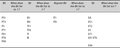
- An 8051 interrupt is of lower priority and has highest latency. Write the instructions, which make it of the highest priority.
- There are n interrupts, 0, 1, 2,…, n−1 in priority order; the highest priority assignment is for 0 and the lowest to interrupt n − 1 and assume that the ith interrupt has execution period = mi ms in 8051. Find the formula for the worst-case latency for the ith interrupt, where i ≤ n − 1 and i ≥ 0. Assume that the vectored priority interrupt service takes place at the end of the ISR only.
- Explain how the order of priorities be reversed given in Table 3.20 in an 8051 application.
- An 8051 uses an SI device in the serial mode-3 duplex way (both T×D and R×D lines are used simultaneously). Write a service routine mnemonics with memory addresses used in each instruction to store the received 8 bytes at the internal RAM between 0x78 and 0x7F and send 8 bytes from the internal RAM between 0x70 and 0x7F.
MULTIPLE CHOICE QUESTIONS
- Interrupt service routine and called routine have the following features:
- Both save the PC at the stack and have an identical instruction for return
- Both save the PC at the stack but have different instructions for the return
- Both save the PC as well as the registers in all MCUs
- The routine is called using the instruction by LCALL, ACALL or CJNE. This is save the PC onto the stack
- Nested interrupts (another ISR starts execution within an ISR) for the maskable sources are permissible in
- 8051 and 80x86
- 68HC11/12
- 8051, 80x86 and 68HC11/12
- 8051 and 68HC11/12
- Which of the following statement is correct?
- Flag sets on interrupt occurrence and does not reset automatically on ISR start for all the sources
- Flag sets on interrupt occurrence and resets automatically on ISR start for all the cases
- Flag sets on interrupt occurrence and resets automatically on ISR start in specific cases, for example, for the case when the vector address is for one interrupt source like INT0 or INT1 or TF0
- Flag resets on interrupt occurrence and sets automatically on ISR start for the case when the vector address is for one interrupt source
- 8051
- IT0 is in TCON SFR and defines the interrupt type (edge-triggered or level-activated interrupt)
- IT0 is in IE SFR and defines the interrupt type (edge-triggered or level-activated interrupt)
- IT0 is in TCON SFR and defines the flag, which sets on interrupt
- IT0 is in IE SFR and defines the flag, which sets on interrupt
- Vector addresses for the multiple sources of interrupts exist in priority order, higher priority vector at the lower address and lowest priority vector at the higher address
- True for 80x86 only and the reverse is true for 68HC11/12
- True for processors 80x86 and 8051 and the reverse is true for 68HC11/12
- True for 8051 and the reverse is true for 68HC11/12
- The reverse is true for all processors
- An 8051 vector address to which CPU vectors for servicing
- is not the ISR start address
- is the address of the interrupt level
- is the address of the pointer for the ISR interrupt
- is the start address of the ISR
- Which of the following statement is correct?
- 8051 primary-level interrupt enable-all bit EA enables the interrupts from all the maskable sources
- EA enables the interrupt from the sources, which are masked by the secondary-level bits and which have a high assigned priority in the IP register
- EA enables the interrupt from the sources, all maskable and unmaskable sources
- EA enables the interrupt from the sources, which are also not masked by the secondary-level bits
- Vectored priority interrupt in 8051 for which the ISR is to be executed takes place
- At the end of each ISR instruction
- At the end of each ISR instruction as well as at the end of the return instruction
- At the end of the ISR return instruction only
- At all instances
- For example, there are three interrupts, 1, 2 and 3 in priority order; highest priority assignment is for 1 and lowest to interrupt 3 and assume that each has an equal execution time of 1 ms in 8051. Let interrupt 1 be under service and let its execution time be 100 μs still left for return at an instant t. Interrupt 2 is pending at t since 200 μs. Now, an interrupt 3 occurs after 50 μs. Interrupt 2 and interrupt 3 latency intervals will be
- 0.3 μs and 1.05 μs, respectively
- 1,300 μs each
- 200 μs and 1,200 μs, respectively
- 1.3 μs and 0.3 μs, respectively
- Consider an ISR
0023 CLR TI
0025 MOV SBUF, @ R0
0027 RETI
Bytes transmitted by successive run of the ISR are as follows:
- Bytes transmitted = 2 if R0 initial value at the first interrupt = 2
- As per bytes put in R0 in the bank defined by RS1-RS0 before the first interrupt
- As per address pointed by R0
- As per SBUF
FILL IN THE BLANKS TYPE QUESTIONS
- Interrupt service routine is executed when a timer T0 overflow indicating flag = ___ and ___ and ___ bits are = ___ and ___ in 8051.
- Interrupt service routine executes from address ___ when a timer T1 overflow interrupt is to be handled and the routine must be from address ___ to ___ because ___ is address for ___.
- 8051 permits pre-emption by at ___ the end of ___ instruction and before the ___.
- Interrupt latency of higher priority interrupt increases when ___.
- Polling in CPUs with vectored priority interrupt is used when ___.
- ___ vectors to an address pointer for the ___ on interrupt.
- ___ MCU vectors to an ISR address for the ___ on interrupt.
- ___ MCU provides for ___ bytes for the codes of ISRs.
- If all interrupts are disabled at the first instruction of ___ and are enabled before the ___ then the advantage is ___.
- If all interrupts are enabled at the first instruction of ___ then the advantage is ___.
- Interrupt service deadline is ___ for a timer interrupt service when a timer overflows after every 4 ms.
- INT0 or INT1 edge-triggered interrupt is used most often in place of level-triggered interrupt because ___.
- ___ and ___ flags on interrupts do not reset automatically on ___ of ___.
- When serial bits are received in mode 3 at 9,600 baud then the interrupt’s deadline is ___.
- The revolutions per minute in a rotating wheel are to be found. We use ___ and ___ interrupts.
- Software interrupts are used when ___.
- Non-maskable interrupts are used ___ processor and the advantage is that ___.
- Advantage of masking is that ___.
- Up to ___ time interval we can mask an interrupt from service.
- Critical section codes are written for ___ on shared variables and at the start of critical code we should ___.