
Chapter 5 Video Technology
In addition to audio technology, television and video technology form the basis of the processing of continuous data in multimedia systems. In this chapter, we consider concepts and developments from this area that are significant for a basic understanding of the video medium. For further details, we make reference to standard works in the area of television technology (see [Joh92]).
Video data can be generated in two different ways: by recording the real world and through synthesis based on a description. We begin our discussion of video technology by covering current and future video standards (analog and digital) with respect to properties of human perception.
5.1 Basics
The human eye is the human receptor for taking in still pictures and motion pictures. Its inherent properties determine, in conjunction with neuronal processing, some of the basic requirements underlying video systems.
5.1.1 Representation of Video Signals
In conventional black-and-white television sets, the video signal is usually generated by means of a Cathode Ray Tube (CRT).
In order to lay the groundwork for a later understanding of the transmission rates of films, we cover television signals in detail here, although we do not consider camera or monitor technology. We begin by analyzing the video signal produced by a camera and the resulting pictures [BF91].
The representation of a video signal comprises three aspects: visual representation, transmission, and digitization.
5.1.1.1 Visual Representation
A key goal is to present the observer with as realistic as possible a representation of a scene. In order to achieve this goal, the television picture has to accurately convey the spatial and temporal content of the scene. Important measures for this are:
• Vertical details and viewing distance
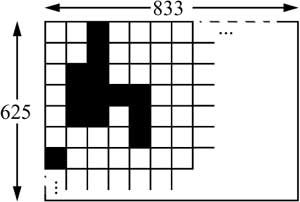
The geometry of a television image is based on the ratio of the picture width W to the picture height H. This width-to-height ratio is also called the aspect ratio. The conventional aspect ratio (for television) is 4/3=1.33. Figure 5-1 shows an example of this ratio.
Figure 5-1 Decomposition of a motion picture. Width to height in ratio 4:3.
The viewing distance D determines the angular field of view. This angle is usually calculated as the ratio of the viewing distance to the picture height (D/H).
The smallest detail that can be reproduced in a picture is a pixel (picture element). Ideally every detail of a picture would be reproduced by a picture element. In practice, however, it is unavoidable that some details lie between scan lines. For such picture elements, two scan lines are necessary. The result is loss of vertical resolution. Measurements of this effect show that only about 70 percent of the vertical details are present in the scan lines. This ratio, known as the Kell factor, is independent of the sampling method, that is, whether the scan lines follow one another sequentially (progressive sampling) or alternately (interlaced sampling).
• Horizontal detail and picture width
The picture width normally used for television is 4/3 times the picture height. The horizontal field of view can be determined using the aspect ratio.
• Total detail content of a picture
The vertical resolution is equal to the number of picture elements of the picture height, while the number of horizontal picture elements is equal to the product of the vertical resolution and the aspect ratio. The product of the picture’s elements vertically and horizontally is the total number of picture elements in the image. However, in the case of television pictures, not all lines (and columns) are visible to the observer. The invisible areas are often used to transmit additional information.
• Depth perception
In nature, humans perceive the third dimension, depth, by comparing the images perceived by each eye, which view from different angles. In a flat television picture, a considerable portion of depth perception is derived from the perspective appearance of the subject matter. Further, the choice of the focal length of the camera lens and changes in depth of focus influence depth perception.
• Luminance
Color perception is achieved by three signals, proportional to the relative intensities of red, green, and blue light (RGB) present in each portion of the scene. These are conveyed to the monitor separately and the tube reproduces them at each point in time (unlike a camera). Often a different signal division is used for transmission and storage: one brightness signal (luminance) and two color difference signals (chrominance). This division will be explained in more detail below.
• Temporal aspects of illumination
Another property of human visual perception is the limit of motion resolution. In contrast to the continuous pressure waves of an acoustic signal, a discrete sequence of individual still pictures is perceived as a continuous sequence. This property is used in television, in films, and for video data in computer systems. The impression of motion is created by presenting a rapid succession of barely differing still pictures (frames). Between frames, the light is cut off briefly. Two conditions must be met in order to represent a visual reality through motion pictures. First, the rate of repetition of the images must be high enough to ensure continuity of movements (smooth transition) from frame to frame. Second, the rate must be high enough that the continuity of perception is not disrupted by the dark intervals between pictures.
• Continuity of motion
It is known that continuous motion is only perceived as such if the frame rate is higher than 15 frames per second. To make motion appear smooth, at least 30 frames per second must be used if the scene is filmed by a camera and not generated synthetically. Films recorded using only 24 frames per second often appear strange, especially when large objects move quickly and close to the viewer, as in pan shots. Showscan [Dep89] is a technology for producing and presenting films at 60 frames per second using 70-millimeter film. This scheme produces a large image that occupies a greater portion of the field of view, resulting in smoother motion.
There are various standards for motion video signals that establish frame rates ensuring suitable continuity of motion. The standard used in the United States, NTSC (National Television Systems Committee), originally set the frame rate at 30Hz. This was later changed to 29.97Hz in order to fix the separation between the visual and audio carriers at precisely 4.5MHz. NTSC scanning equipment represents frames using the 24Hz standard by translating them to the 29.97Hz scanning rate. A European standard for motion video, PAL (Phase Alternating Line), adopted a repetition rate of 25Hz, but uses a frame rate of 25Hz.
• Flicker
If the refresh rate is too low, a periodic fluctuation of the perceived brightness can result. This is called the flicker effect. The minimum refresh rate to avoid flicker is 50Hz. Achieving continuous, flicker-free motion would thus require a high refresh rate. However, in both movies and television, there are technical measures that allow lower refresh rates to be used.
The flicker effect would be very disturbing in films with, for example, 16 pictures per second without any additional technical measures. In order to reduce flicker, the light is interrupted an additional two times during the projection of a frame, yielding a picture refresh rate of 3×16Hz = 48Hz.
In television, display refresh buffers—expensive until recently—can be used to alleviate the flicker effect. Picture data are written into the buffer at a rate higher than needed for motion resolution (e.g., 25Hz). The monitor reads the display data out at a rate that eliminates the flicker effect (e.g., 70Hz). This corresponds to the 70Hz refresh rate of higher quality computer screens.
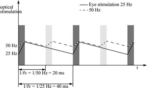
In television, the full picture is divided into two half pictures consisting of interleaved scanning lines. One half of the picture is transmitted after the other using interlaced scanning. The transmission of full pictures takes place at around 30Hz (exactly 29.97Hz), or 25 Hz in Europe, whereas the transmission of half pictures takes place at 2×30Hz = 60Hz or 2 ×25Hz = 50Hz, respectively. Figure 5-2 shows an example of this. Visual perception drops considerably more with a refresh rate of 25Hz (unbroken line) than 50Hz.
Figure 5-2 Flicker effect. Eye stimulation with refresh rates of 25 Hz and 50 Hz.
5.1.2 Signal Formats
Video signals are often transmitted to the receiver over a single television channel. In order to encode color, consider the decomposition of a video signal into three subsignals. For reasons of transmission, a video signal is comprised of a luminance signal and two chrominance (color) signals. In NTSC and PAL systems, the component transfer of luminance and chrominance in a single channel is accomplished by specifying the chrominance carrier to be an odd multiple of half the line-scanning frequency. This causes the component frequencies of chrominance to be interleaved with those of luminance. The goal is to separate the sets of components in the receiver and avoid interference between them before the primary color signals are recovered for display. In practice, however, there are degradations in the picture quality, known as color crosstalk and luminance crosstalk. These effects have led the manufacturers of NTSC receivers to reduce the luminance bandwidth to less than 3 MHz, under the carrier frequency of 3.58MHz and far below the broadcast signal theoretical maximum limit of 4.2MHz. This limits the vertical resolution in such devices to about 25 lines. Chrominance and luminance signals are separated by using a simple notch filter tuned to the subcarrier’s frequency. Today comb filters are also used for this purpose. The transmitter also uses a comb filter in the coding process.
Several approaches to color encoding are described below.
5.1.2.1 Color Encoding
• RGB signal
An RGB signal consists of separate signals for red, green, and blue. Every color can be encoded as a combination of these three primary colors using additive color mixing. The values R (for red), G (for green), and B (for blue), are normalized such that white results when R + G + B =1 in the normalized representation.
• YUV signal
Since human vision is more sensitive to brightness than to color, a more suitable encoding separates the luminance from the chrominance (color information). Instead of separating colors, the brightness information (luminance Y) is separated from the color information (two chrominance channels U and V). For reasons of compatibility with black-and-white receivers, the luminance must always be transmitted. For black-and-white reception, the utilization of the chrominance components depends on the color capabilities of the television set.
The YUV signal can be calculated as follows:
Y = 0.30 R + 0.59 G + 0.11 B
U = (B – Y) × 0.493
V = (R – Y) × 0.877
An error in the resolution of the luminance (Y) is more serious than one in the chrominance values (U,V). Thus the luminance values can be encoded using higher bandwidth than is used for the chrominance values.
Due to the different component bandwidths, the encoding is often characterized by the ratio between the luminance component and the two chrominance components. For example, the YUV encoding can be specified as a (4:2:2) signal. Further, the YUV encoding is sometimes called the Y, B – Y, R – Y signal, from the dependencies among U, B – Y, V and R – Y in the equations above.
• YIQ signal
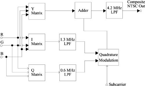
A similar encoding exists for NTSC’s YIQ signal:
Y = 0.30 R + 0.59 G + 0.11 B
I = 0.60 R – 0.28 G – 0.32B
Q = 0.21 R – 0.52 G + 0.31 B
A typical NTSC encoder is shown in Figure 5-3. It produces the I and Q signals, then performs a quadrature amplitude modulation on the suppressed chrominance subcarrier and adds the modulated signal to the luminance Y. The signals are also blanked and synchronized.
Figure 5-3 YIQ encoding operations of an NTSC system.
5.1.2.2 Composite Signal
An alternative to component encoding is to combine all information in one signal. This implies that the individual components (RGB, YUV, or YIQ) must be combined in a single signal. The basic information consists of luminance information and chrominance difference signals. However, the luminance and chrominance signals can interfere since they are combined into one signal. For this reason, television technology uses appropriate modulation methods aimed at eliminating this interference.
The basic bandwidth needed to transmit the luminance and chrominance signals for the NTSC standard is 4.2MHz.
5.1.2.3 Computer Video Format
The video format processed by a computer depends on the video input and output devices. Current video digitalization hardware differs with respect to the resolution of the digital images (frames), quantization, and the frame rate (frames/second). Motion video output depends on the display hardware used, usually a raster display. The typical architecture of such a device is shown in Figure 5-4.
Figure 5-4 Architecture of a raster display.
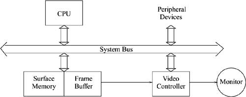
The video controller displays the image stored in the frame buffer, accessing the buffer through a separate port as often as required by the video scanning rate. The most important task is the constant refresh of the display. Due to the disturbing flicker effect, the video controller cycles through the frame buffer, one scan line at a time, typically 60 times/second. To display different colors on the screen, the system works with a Color Look-Up Table (CLUT or LUT). At any given time, a limited number of colors (n) are available for the whole picture. The set of the n most frequently used colors is chosen from a color palette consisting of m colors, whereby in general n « m.
Some examples of well-known computer video formats are presented here. Each system supports various resolutions and color presentations.
• The Color Graphics Adapter (CGA) has a resolution of 320×200 pixels with simultaneous display of four colors, among other modes. The necessary storage capacity per frame is thus
![]()
• The Enhanced Graphics Adapter (EGA) supports display resolution of 640×350 pixels with 16 simultaneous colors. The necessary storage capacity per frame is
![]()
• The Video Graphics Array (VGA) works mostly with a resolution of 640×480 pixels with 256 simultaneous colors. The monitor is controlled via an analog RGB output. The necessary storage capacity per frame is
![]()
• The Super Video Graphics Array (SVGA) can present 256 colors at a resolution of 1,024×768 pixels. The necessary storage capacity per frame is
![]()
Other SVGA modes include 1,280×1,024 pixels and 1,600×1,280 pixels.
SVGA video adapters are available with video accelerator chips that overcome reduced performance at higher resolution and/or higher numbers of colors [Lut94]. Video accelerator chips can be used to improve playback of video, which would normally appear in a window of at most 160×120 pixels. A video accelerator chip allows for playback of recorded video sequences at a significantly higher rate and quality [Ann94c].
5.2 Television Systems
Television is one of the most important applications driving the development of motion video. Since 1953, television has undergone many far-reaching changes. This section provides an overview of television systems, encompassing conventional black-and-white and color systems, enhanced resolution television systems intended as an intermediate solution, and digital interactive video systems and Digital Video Broadcasting (DVB).
5.2.1 Conventional Systems
Black-and-white and current color television is based on the properties of video signals as described in Section 5.1.1. Early on, different parts of the world adopted different video standards. Conventional television systems use the following standards:
• NTSC stands for National Television Systems Committee and is the oldest and most widely used television standard. The standard originated in the US and uses color carriers of approximately 4.429MHz or approximately 3.57MHz. NTSC uses quadrature amplitude modulation with a suppressed color carrier and a refresh rate of about 30Hz. A picture consists of 525 rows.
NTSC can use 4.2MHz for the luminance and 1.5MHz for each of the two chrominance channels. Television sets and video recorders use only 0.5MHz for the chrominance channels.
• SECAM stands for Sequential Couleur avec Memoire and is used primarily in France and Eastern Europe. In contrast to NTSC and PAL, it is based on frequency modulation. Like PAL, SECAM uses a refresh rate of 25Hz. Each picture consists of 625 rows.
• PAL stands for Phase Alternating Line and was proposed in 1963 by W.Bruch of Telefunken. It is used in parts of Western Europe. Figure 5-5 is a schematic of the picture preparation process.
Figure 5-5 Color signal preparation in the PAL standard: converting RGB to CCVS.
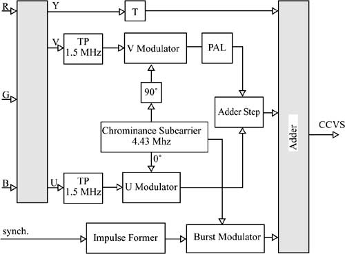
The color carrier lies in the CCVS (Color Composite Video Signal) spectrum about 4.43MHz from the picture carrier. The basic principle is quadrature amplitude modulation, whereby the color carrier and the chrominance signal U are directly multiplied. The color carrier, shifted by 90 degrees, is then multiplied by the chrominance signal V. This product is then added to the shifted color carrier. This is a normal quadrature amplitude modulation. In every other row, in addition to the actual quadrature amplitude modulation, the phase of the modulated V signal is rotated in order to reduce phase errors.
5.2.2 High-Definition Television (HDTV)
Research in the area of High-Definition Television (HDTV) began in Japan in 1968. This phase is considered to be the third technological change in television, after black-and-white and the introduction of color television. HDTV strives for picture quality at least as good as that of 35mm film.
Promoters of HDTV pursued the goal of approaching integrating the viewer with the events taking place on the screen [Hat82]. Television systems, filming techniques, and viewing requirements were chosen in order to give the viewer the impression of being involved in the scene.
The parameters that had to be defined in order to achieve this goal were resolution, frame rate, aspect ratio, interlaced and/or progressive scanning formats, and viewing conditions [Org96].
• Resolution
Compared to conventional systems, an HDTV picture has about twice as many horizontal and vertical columns and lines, respectively. The improved vertical resolution is achieved by using more than 1,000 scanning lines. Improved luminance details in the picture can be accomplished with a higher video bandwidth, about five times that used in conventional systems. Two resolution schemes are recommended for practical applications: the so-called “High 1440 Level” with 1,440×1,152 pixels and the “High Level” containing 1,920×1,152 pixels.
• Frame rate
The number of frames per second was bitterly discussed in the ITU Working Groups. For practical reasons, namely compatibility with existing TV systems and with movies, agreement on a single HDTV standard valid worldwide could not be achieved; options of 50 or 60 frames per second were established. Newly developed, very efficient standard-conversion techniques, based in part on movement estimation and compensation, can mitigate this problem.
• Aspect ratio
The aspect ratio is defined as the ratio of picture width to picture height. Originally, a ratio of 16:9 = 1.777 was adopted; the ratio in current televisions is 4:3.
• Interlaced and/or progressive scanning formats
Conventional TV systems are based on alternation of scanning lines—each frame is composed of two consecutive fields, each containing half the scanning lines of a picture, which are scanned and presented in interlaced mode. In progressive scanning, used for example in computer displays, there is only one such field per picture and the number of scanning lines per field is doubled.
• Viewing conditions
The field of view and thus the screen size play an important role in visual effects and thus also for the feeling of “reality.” Early studies found that the screen area must be bigger than 8,000cm2. The line count per picture is about twice as large as in conventional television, so the normal viewing distance can be halved compared to conventional systems and results in three times the picture height (3H).
In 1991, researchers at NTT Labs reported further progress in HDTV technology [OO91]. Their concept integrated various video media with their corresponding quality levels (communication, broadcast, and display) into one system. In order to achieve this integration, a minimum spatial resolution of 2k×2k pixels is needed, along with temporal resolution of at least 60 frames per second and a signal resolution of at least 256 steps (corresponding to 8bits). A resolution of 2k×2k corresponds to a high-resolution photo or a color A4 print.
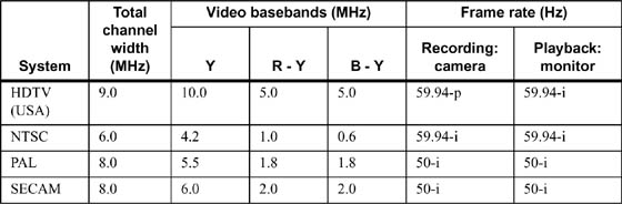
Table 5-1 Properties of TV systems (p: progressive, i: interlaced).
5.3 Digitization of Video Signals
Before a motion picture can be processed by a computer or transmitted over a network, it must be converted from an analog to a digital representation.
This digitization process consists of the three steps of sampling, quantization, and coding. In determining the sampling frequency, the Nyquist Theorem must be followed. This theorem states that the signal being sampled cannot contain any frequency components that exceed half the sampling frequency. In order to prevent the baseband from overlapping with repeating spectra and to allow for real hardware components not behaving ideally, the sampling rate is normally chosen somewhat higher than the limit dictated by the Nyquist Theorem.
Since the gray value of a sampled spot can take on any value in a continuous range, it must be quantized in order to be processed digitally. The gray-scale is subdivided into several ranges, and each pixel is assigned only one of these values. In order to achieve acceptable quality in an image reconstructed from quantized pixels, it is a good idea to use at least 256 quantization steps.
The CCIR (Consultative Committee International Radio, currently ITU) had already passed an international standard for digital television in 1982. This standard (ITU 601) describes specific scanning resolutions and covers scanning and coding. There are two possible types of digital coding: composite coding and component coding.
5.3.1 Composite Coding
The simplest way to digitize a video signal is to sample the entire analog signal (CCVS—Color Composite Video Signal). Here all signal components are converted together to a digital representation. This “integrated coding” of an entire video signal is fundamentally simpler than digitizing separate signal components (luminance signal and two chrominance signals). However this approach also has numerous drawbacks:
• There is frequently disturbing crosstalk between the luminance and chrominance information.
• The composite coding of a television signal depends on the television standard used. This would lead to a further difference among the various standards, in addition to different numbers of scanning lines and motion frequencies. Even if multiplexing methods were used for further signal transmission, the standards difference would be bothersome since different transmission techniques would have to be used for different digital television standards.
• Because the luminance information is more important than the chrominance information, it should also take more bandwidth. When composite coding is used, the sampling frequency cannot be adapted to bandwidth requirements of different components. If component coding is used, it is possible to decouple the sampling frequency from the color carrier frequency.
Having detailed the disadvantages of composite coding, we now consider the properties of component coding.
5.3.2 Component Coding
Component coding is based on the principle of separate digitization of the components, that is, the luminance and color difference signals. These can then be transmitted together using a multiplexing method. The luminance signal (Y), which is more important than the chrominance signal, is sampled at 13.5MHz, while the chrominance signals (R– Y, B– Y) are sampled at 6.75MHz. The digitized luminance and chrominance signals are uniformly quantized using 8bits. Due to the different component bandwidths in the ratio 4:2:2, this technique produces 864 sampling values per line for luminance (720 are visible) and 432 for each of the chrominance components (360 are visible). In PAL, for example, a frame consists of 575 lines and there are 25 full frames per second. The high data rate and the fact that these signals do not fit in the PCM hierarchy (139.264Mbit/s, 34.368Mbit/s) are problematic. Thus several substandards with lower data rates have been defined. The data rates are easy to derive from the bandwidths of the components (13.5MHz, 6.75MHz, 6.75MHz).
The standardized sampling frequency of 13.5MHz for R, G, B, or Y baseband signals [CCI82] and the 8-bit quantization result in a data rate of 108Mbit/s for each individual signal. For the chrominance components Cr and Cb, the reduced sampling rate of 6.75 MHz corresponds to 54 Mbit/s. The sampling frequency of 13.5 MHz is defined as an integral multiple in both the 625- and the 525-line TV standards.
Table 5-2 Comparison of component coding.
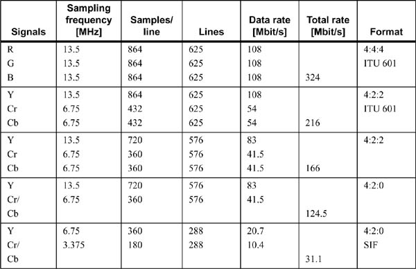
The resulting data rates for transmitting R, G, B (format 4:4:4) and Y, Cr, Cb (format 4 : 2 : 2), are 324 Mbit/s and 216 Mbit/s, respectively. These relationships are listed in Table 5-2. In the 601 standard there is an option of using 10-bit signal resolution for broadcast equipment and studio connections; the data rate increases accordingly. For the 16:9 aspect ratio, a sampling rate of 18MHz instead of 13.5MHz was proposed in order to provide sufficient bandwidth for this new picture format [CCI82]. This increases the data rate by a factor of 4/3.
Assuming a simple data reduction scheme is used, for example skipping the blanking intervals, the total data rate can be reduced from 216Mbit/s to 166Mbit/s, and further to 124.5Mbit/s using line-sequential Cr/Cb transmission (format 4:2:0). Reducing sampling (subsampling) in the horizontal and vertical directions by a factor of two yields a data rate of 31.1Mbit/s (so-called Source Input Format, SIF). SIF is a special picture format with progressive line scanning (no interlace) defined to work independently of the presentation. All of the values listed in Table 5-2 assume a frame rate of 25Hz and 8-bit quantization.
5.4 Digital Television
When the topic of digital television was taken up by the relevant Working Groups of the ITU, discussion centered around the digital representation of television signals, that is, composite coding or component coding. After considerable progress in compression technology (see Chapter 7) and an agreement to use exclusively component coding, at least in the TV studio, the work concentrated on the distribution of digital signals and consequently took on more of a system-oriented viewpoint.
In Europe, the development of digital television (Digital TeleVision Broadcasting, DTVB or—less precisely—Digital Video Broadcasting, DVB) started in the early 90s. At this time, universities, research facilities, and businesses were already intensely working on pushing a European HDTV system. Interested partners founded a European consortium—the European DVB Project—that made quick headway upon beginning work and thus played a major role in the preliminary standardization work of all digital television system components. Excluded, however, are studio and display technologies [FKT96].
One of the first important decisions was the selection of MPEG-2 for the source coding of audio and video data and of the MPEG-2 system technology for the creation of elementary program streams and transport streams (see Compression in Section 7.7). Although the original MPEG-2 standard [Org96] met practical requirements, it was too broad to be implemented economically in its entirety. As a result, the syntax and possible parameters were restricted; these DVB recommendations are contained in the “Guidelines Document” [Ins94].
Typical documents that describe the DVB system components are [Ins95] and [Eur94]. The former, also called DVB-TXT, specifies how to handle “analog” teletext in a DVB environment. A mechanism for transmitting all types of subtitles and graphical elements as part of the DVB signal is described in [Eur96]. Program descriptions and navigation tools are covered by the Service Information Document (SI) [Eur94].
Satellite connections, CATV networks, and (S)MATV ((Small) Master Antenna TV) systems are best suited for distributing digital television signals. Terrestrial broadcast services, for example, data distribution to households over telephone connections or using “Multichannel Microwave Distribution Systems” (MMDS), are other technical possibilities. Suitable transmission systems had to be developed for all these options and standardized by the DVB Project. The standard for terrestrial broadcast (DVB-T) is [Eur96].
The European Telecommunications Standards Institute (ETSI) adopted the DVB system digital broadcast proposals for satellites (DVB-S) and for CATV systems (DVB-C) as official standards. These are ETS 300421 and ETS 300429. The standards documents ETS 300472, ETS 300468, and ETS 300473 apply to (S)MATV.
If microwaves are used to transmit DVB signals, there are two specifications, depending on the frequency range used. ETSI standards also describe MMDS for use at frequencies above 10GHz (DVB-MS). This transmission system is based on the use of DVB-S technology. ETS 749 is applicable to frequencies below 10GHz. This specification is based on DVB-C technology and is thus also designated as DVB-MC.
Additionally, recommendations were published for conditional access, for establishing backward channels in interactive video applications, and for the private use of specific networks.
In conclusion, the DVB solutions for digital television afford many advantages, the most important being the following:
• the increased number of programs that can be transmitted over a television channel,
• the option of adapting video and audio quality to each application,
• the availability of exceptionally secure encryption systems for pay-TV services,
• the availability of tools to develop and implement new services such as data broadcast, multimedia broadcast, and video-on-demand, and
• the option of integrating new Internet services representing the “convergence” of computers and TV.