
Upon completion of this chapter, you should be able to
Explain the purpose of logical files.
Explain the differences between physical files and logical files.
Describe the various forms of logical files that can be used to define access paths to data stored in physical files.
Demonstrate the use of logical files in application programs.
There will be times when a user needs to access a physical file in some manner other than the way the physical file is defined. For example, a user may want to access employee records using either a Social Security number or a name as the key field. Similarly, a user may wish to group employees and print or display them by department number or city. An accounts receivable clerk may wish to access only those accounts that exceed a certain balance. In another situation, a user may wish to select or omit specific records from a physical file or even select or omit fields within the records. A logical file can be used to accomplish all of these tasks.
A logical file defines an access path to data stored in one or more physical files. Logical files do not contain any data themselves but provide a view of data from physical files. The logical view allows a user to decide what data are to be retrieved from the physical file or files and the format in which they are to appear.
Logical files may be used to
Sequence data in a physical file in a different order.
Select or omit specific records from physical files.
Select or omit specific fields within records from physical files.
Access data from two or more physical files.
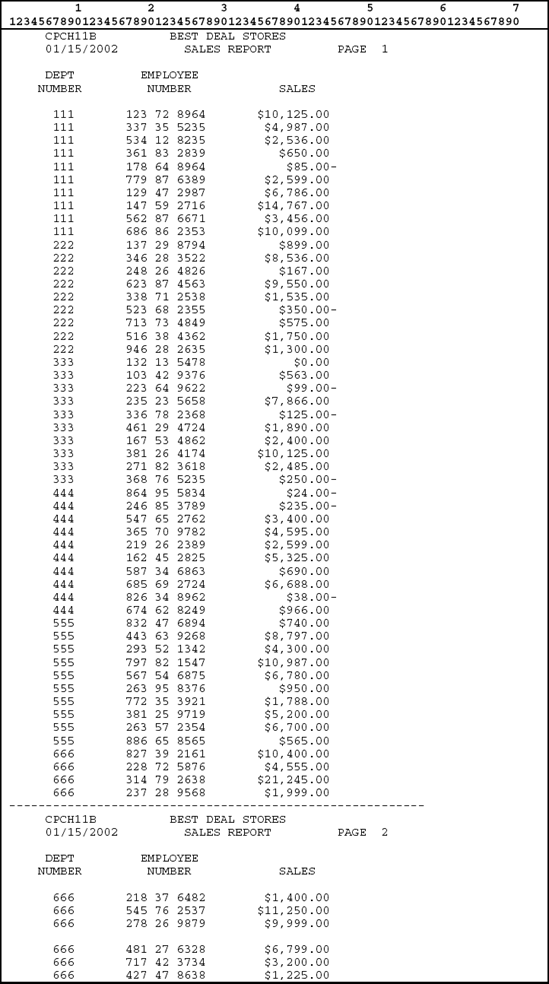
Consider the sales report in Figure 11.1. This sales report provides a listing of each employee in the employee pay file EMPPAYPF.
The employee pay file EMPPAYPF in Figure 11.2 is the physical file containing the actual employee pay data and is keyed on employee number. Thus, when records are read from the EMPPAYPF physical file, the records are accessed in employee number sequence.


Program CPCH11A in Figure 11.3 is the program that reads the EMPPAYPF physical file and produces the sales report in Figure 11.1. The physical file EMPPAYPF is defined as a keyed sequence file with employee number as the key field. The file is accessed sequentially by program CPCH11A. Thus, the employee records are listed in the report in employee number sequence.

Quite often when processing records from a physical file, records need to be in a particular sequence that is different than the keys fields of the physical file. For example, suppose the user requests that the report in Figure 11.1 list employees by department number. Accessing the EMPPAYPF physical file will not produce the correct results because EMPPAYPF is keyed on employee number.
Accessing the data directly from the file will not return the data in the required sequence, that is, in department number sequence. Consider the example in Figure 11.4, where records are not in sequence by department number.

The first step in solving this problem is to create a logical file over the EMPPAYPF physical file so that the records are sequenced in department number order. A simple logical file is a logical file that is created over, or based on, a single physical file and provides a different view of data in the physical file.
Figure 11.5 illustrates the systems flowchart for this example, in which a logical file is built over the physical file that creates a new access path to the data in the physical file.
Systems flowchart
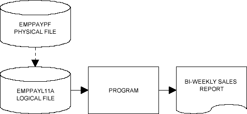
Since this logical file is built over the physical file EMPPAYPF, it is the logical file that maintains the key sequence of the records for this program. The logical file ensures that records from the EMPPAYPF are read into the program in department number order.
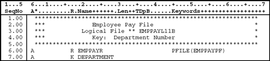
When defining a simple logical file, one record format is defined. Figure 11.6 illustrates the logical file EMPPAYL11B required to access the employee records by department number. The DDS are described following the figure.
All data description specifications have the letter A in position 6.
Lines 1.00–5.00: Comment lines (*in the Comment field, position 7) that describe the logical file.
File Level
There are no file level entries for this logical file.
Note that the keyword UNIQUE is not specified for this logical file. Remember that the keyword UNIQUE indicates that no two key values can be the same. Since more than one person can work in a particular department, the logical file must allow for duplicate key values. This allows the program to retrieve the records in department number order, where there can be more than one employee record for a particular department.
Record Level (Line 6.00)
Line 6.00: The record level keyword PFILE specified in position 45 associates this logical file with the physical file EMPPAYPF. This means that this logical file is built over the physical file EMPPAYPF.
The PFILE keyword allows this logical file to reference back to the physical file for the fields and their attributes.
The file-name can be qualified by a library name. If a library name is not specified in the PFILE keyword, the library list is used to locate the file. The physical file must exist before the logical file is compiled.
The letter R specified in the Name Type field (position 17) indicates that this line is defining the record format name. The name of the record, EMPPAYR, is left-justified in the Name field (positions 19–28). Note that this is the same record format name specified in the physical file EMPPAYPF. Thus, the logical file being described shares the record format from the physical file. This is allowed since this logical file is referencing the physical file (PFILE) and all fields are included in the record format.
Field Level
There are no field level entries for this logical file.
Since no fields are specified directly in this logical file, all fields from the EMPPAYPF physical file are included in the record format for the logical file.
To write the specifications for the program, the software developer needs to refer to the DDS of the physical file EMPPAYPF so the correct field names are used.
Key Level (Line 7.00)
Logical files typically have one of more fields designated as key fields. These key fields are specified after the field level specifications. The key field-names must be defined at the field level in the record format. When a key is specified for a logical file, a keyed sequence access path is created so data are retrieved from the physical file in the sequence specified by the key fields.
Line 7.00: The letter K in the Name Type field (position 17) indicates that the field specified in the Name field (positions 19–28) is the key field for this logical file. Thus, the Department Number, DEPARTMENT, is the key field.
The sales report in Figure 11.7 is produced when the logical file CPCHL11B is used to access the data in the physical file EMPPAYPF.
When a logical file is built over a physical file and used in a program, it is usually defined as an externally described file. Program CPCH11A can be modified to use the logical file CPCHL11B and produce the sales report in Figure 11.7. Figure 11.8 identifies the necessary changes in bold. As you can see, the logical file is defined similarly to a physical file.
The file name on the ASSIGN clause and COPY statement must be changed to EMPPAYL11B so that the logical file is accessed instead of the physical file.
The logical file is keyed on department number. Since there could be several employees working in the same department, the program must allow for records with the same value in the key field. The phrase WITH DUPLICATES is added to the RECORD KEY clause to allow records with the same key field or duplicate keys.

Examine the sales report in Figure 11.7 and observe that the employees are listed in department number order. Also observe that within each department the employees are listed in random order. The reason for this is that when a logical file is used, records are retrieved directly from the data file of the physical file. The index file of the physical file is not used. Thus, the records are accessed in department number order. Beyond that the records are retrieved from the data file in the same sequence in which they are physically stored in the file.
This problem can be corrected by using the logical file in Figure 11.9. Logical file CPCHL11C provides an access path that maintains records in employee number sequence within department number.
The sales report in Figure 11.10 is produced when program CPCH11A is modified to use logical file CPCH11C. Note that the employees are listed by employee number within department number.


In most applications requiring logical files, it is not necessary to include all of the fields from the physical file in the logical file. Figure 11.11 illustrates how to describe a logical file with a record format that lists only the fields that are required in the program using the logical file.
In this logical file, the record format contains specific fields from the record format of the physical file. Since a different record format is being defined, a different record name (EMPPAYR1) has been specified for the logical file.
Notice that the data type, length, and decimal positions for the fields are not specified in the logical file. Since the fields specified in the logical file are fields from the physical file, they assume the same attributes as specified in the physical file.

At times, it may be necessary to select certain records or exclude certain records in a physical file based on some criteria. A logical file can be used to select and omit records from a physical file. The process of selecting and omitting records is based on comparisons identified in position 17 (Type field) of the DDS for the logical file.
To select or omit records, specify an S (select) or O (omit) in position 17 (Type field) of the DDS for the logical file. In the name field (positions 19 through 28) specify the name of the field that will be used in the selection or omission process. In the Keyword field (positions 45 through 80) specify the comparison. Select and omit specifications appear after key specifications (if keys are specified).
Records can be selected and omitted by several types of comparisons.
VALUES. The contents of the field are compared to a list of not more than 100 values. If a match is found, the record is selected or omitted. In the following example, a record is selected if one of the values (1133 or 7315) specified in the VALUES keyword is found in the STORENO field.

In this example, the logical file retrieves from the physical file only records that have a STORENO value of 1133 or 7315. All other records are omitted from the access path. The omitted records remain in the physical file but are not retrieved for the logical file.
With this logical file, any record can be added to the physical file, but only selected records that match the select and omit criteria can be retrieved using the select and omit access path.
RANGE. The contents of the field are compared to lower and upper limits. If the contents are greater than or equal to the lower limit and less than or equal to the upper limit, the record is selected or omitted. In the following example, all records with a range 1100 through 7500 in the STORENO field are selected.

COMP. The contents of a field are compared to a value or the contents of another field. Valid comparison codes are EQ, NE, LT, NL, GT, NG, LE, and GE. If the comparison is met, the record is selected or omitted. In the following example, a record is omitted if the HRSWORKED field is less than or equal to 40 (employee has worked overtime).

In this example, a selection of HRSWORKED COMP(GT 40) could have been used.
The value for a numeric field for which the COMP, VALUES, or RANGE keyword is specified is aligned based on the decimal positions specified for the field
and is filled with zeros where necessary. If decimal positions were not specified for the field, the decimal point is placed to the right of the farthest right digit in the value. For example, for a numeric field with length 5 and decimal position 2, the value 1.2 is interpreted as 001.20 and the value 100 is interpreted as 100.00. The status of a record is determined by evaluating select and omit statements in the sequence specified. If a record qualifies for selection or omission, subsequent statements are ignored.
Normally, the select and omit comparisons are treated independently from one another. This means that the comparisons are ORed together. That is, if the select or omit comparison is met, the record is either selected or omitted. If the condition is not met, the system proceeds to the next comparison. In the following example, a record is selected if the SALES field is greater than 6000 OR HRSWORKED is greater than 40.

To connect comparisons together, simply leave a space in position 17 of the DDS. Then, all the comparisons that are connected in this fashion must be met before the record is selected or omitted. That is, the comparisons are ANDed together. In the following example, a record is selected if the STORENO field contains a value of 1133 AND the HRSWORKED field is greater than 40.

The system does not ensure that any additions or changes through a logical file will allow the record to be accessed again in the same logical file. For example, if the selection values of the logical file specifies only records with 1133 in the STORENO field and the program updates a record for an employee at store 1133 with 35 in the HRSWORKED field, the program cannot retrieve the record again using this logical file.
Before creating a logical file, the physical file on which the logical file is based must already exist as a file object. To create a logical file
Design the logical file using data description specifications (DDS).
Enter the DDS for the logical file into a source file (QDDSSRC).
Compile the logical file into a file object (*file) using one of the following methods:
Use the Create Logical File (CRTLF) command as follows:
CRTLF FILE (COBOL2DLIB/EMPPAYL11A)
where EMPPAYL11A is the name of the logical file and COBOL2DLIB is the name of the library where the compiled object is to be stored.
Enter 14 in the option field beside the logical file-name on the Work With Members Screen. This option will submit a batch job that will execute the CRTLF command and compile the logical file into a file object.
A logical file containing multiple-record formats allows software developers to use related records from two or more physical files by referring to only one logical file. Each record format is always associated with one or more physical files.
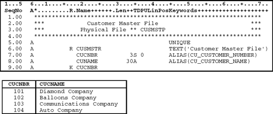
Figures 11.12 and 11.13 illustrate two physical files. The customer master file in Figure 11.12 contains a record for each customer, while the customer contact file in Figure 11.13 contains a record for each contact person for each customer.

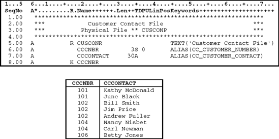
Figure 11.14 illustrates how to create a logical file, CUSCONL11H, with two record formats. One record format is defined for customer master records from the physical file CUSMSTP; the other is defined for customer contact records from the physical file CUSCONP.
Both record formats use one key field, Customer Number, for sequencing. It is, however, permissible to have more than one key field. In addition, the second file, or secondary file, being described could have more key fields than the first record format. This allows the matched records to be further sequenced.

In a logical file with more than one record format, key field definitions are required. Each record format has its own key definition, and the record format key fields can be defined to merge the records of the different formats. Each record format does not have to contain every key field in the key.
The access path for the logical file CUSCONL11H arranges records from both the CUSMSTP and CUSCONP files as shown in Figure 11.15. Record formats for both physical files are keyed on customer number as the common field. Because of the order in which they were specified in the logical file description, they are merged in customer number sequence with duplicates between files retrieved first from the customer master CUSMSTP file and second from the customer contact CUSCONP file.

Figure 11.15. Information from customer master file and customer contact file as it appears in a multiple-record logical file.
When this logical file is read sequentially, the customer master record containing the lowest customer number is retrieved first. Then, records with the same customer number are retrieved from the customer contact file. Once all records for the first customer number are read from the customer contact file, the next customer master record is read. This continues until all records have been processed through the logical file.
The data shown in Figure 11.15 give the appearance that the records from the two physical files were merged and sorted by customer number. We know that this is not the case, since logical files do not contain data. What happens is that the logical file builds access paths to the records in both physical files based on the record formats specified in the logical file.
With relational database design, most databases incorporate some degree of file normalization. Normalization is a methodology for arranging fields (columns in database terminology) into files (tables) so that redundancy among the nonkey fields is eliminated. Thus, when a database is normalized, each file within the database contains data for a single entity.
Designing systems using normalization techniques can make accessing information more difficult since, in general, the design spreads data among numerous files. Fortunately, there is a file type called join logical file that helps gain easy access to normalized data.
Joins can be created using data description specifications (DDS), Open Query File (OPNQRYF), SQL, and QUERY. With DDS, a permanent view can be created that is automatically maintained by the system. If a program adds, changes, or deletes a record in any of the files that make up the join, it is reflected in the join logical file. This method keeps current information available on a full-time basis, which is a powerful advantage over the other methods.
A join logical file is a way to view data from two or more physical files (up to 32) as if all the data were in one file and one record format. The record format (only one is allowed) can be made up of any of the fields contained in any of the files to be joined. Join logical files (like other logical files) are made up of pointers to the data, not the actual data. Therefore, join logical files use disk space efficiently. Another benefit is that the access path is faithfully maintained by the system.
As great as join logical files are, there is a limitation that may cause you to use them only in certain situations: You cannot change or add records directly to the join logical file. You must perform your updates to the actual physical file or nonjoin logical files.
A join logical file can contain only one primary file. All other files are considered secondary. For files to be joined, they must share common fields. Any time there is a match (that is, the values of the common field are equal between the files being joined), the data from the two files are combined into the join record format.
For example, if the customer file in Figure 11.16 is the primary file, and it determines which records are included in the resulting join file, then every record in the primary file that has a matching customer number record in the secondary file (the customer contact file, shown in Figure 11.17) is included. If more than one secondary record is found for a corresponding customer record, the customer record is included for each secondary record match. For example, the
Diamond Company is included twice in the joined file (see Figure 11.18) because two contact records exist for Diamond's customer number.
Customer number 103 (Communications Company) was not included in the joined file because there was no match in the secondary file. Unless a special keyword is used (as you will see in Example 1), only primary records with a matching secondary record are included in the join.
In Figure 11.18, secondary file record Betty Jones is not included. The only way to include this record is to make the customer contact file primary. However, changing the primary file means that records you were expecting from the original primary file may not be included in the join.


Let's consider three examples, ranging from basic to complex, to show how to write join logical files. Each example is a practical illustration and includes the most commonly used options.
This example illustrates a join of two physical files, customer file (CUSMSTP) and customer contact file (CUSCONP). The DDS and records for CUSMSTP and CUSCONP were already illustrated in Figures 11.16 and 11.17, respectively. Figure 11.18 illustrates the DDS used to describe the join logical file CUSCONJ11I along with the resulting records.
The file-level keyword JDFTVAL (line 5) is used whenever there is a possibility that a secondary file record does not exist for a primary record, yet you still want to include the primary record in the join. In this case, the system will supply a default value from the secondary file's field.
The default value for a character field is blank and zero for numeric fields. However, default values can be defined in the physical file through the DFT keyword. In this example, "No Contact Name Exists" is the default for the CCCONTACT field (see Figure 11.17, line 8). As a result, the join file is automatically provided with this value when a secondary record does not exist (see Figure 11.18).
The JFILE keyword (line 6) in Figure 11.19 is used to specify all of the files that are going to be joined, so all further references can be made by a number representing the relative position of the file listed. This shorthand method can save you from keying a file-name more than once, but it is not recommend since there is no need to make interpretation of your specifications any more difficult just to save a few keystrokes.
The next keyword is JOIN, which supplies the name of the common field that will link the two files specified with the JFILE keyword. Regardless of whether two or 32 files are joined, the files are joined in pairs indicated by the JOIN keyword. If more than two files were being joined, there would be more than one JOIN keyword, one for each pair of files. Always specify a J in column 17 of the A-spec containing the JOIN keyword.
Join fields must have the same field attributes (length, data type, and decimal positions) but need not have the same name. If the join fields do not have matching attributes, one or both of them can be redefined. Redefining fields for this purpose is not discussed in this book.
As mentioned earlier, a common field must exist between a join pair. These fields are indicated by the JFLD keyword on line 8. In this example, the two fields are CUCNBR and CCCNBR.
Only one record format for the CUSCONJ11I file can be defined, and it cannot be shared. You can reference the name of any field from any of the files included in the join. Any of the fields from any of the files can be used as select/omit fields, but they must be defined in the join record format. In this example and the next two, the CUNAME field from the primary file CUSMSTP is used as the key field. Key fields can only be fields from the primary file.
One join keyword that will not be used in any of the examples is JREF, a field-level keyword used when fields from different files have the same name. For example, say the customer file used NAME to define customer name and the contact file used NAME to define the contact name. A reference to NAME would
need to be qualified with the JREF keyword followed by the name of the file from which the information is to be retrieved.

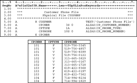
This example uses a phone number file (CUSPHNP) as the secondary file joined to the same customer file used in Example 1. The phone file can contain any number of phone numbers (voice and fax) for a company. Voice phones are indicated by phone type 'V' and fax phones by phone type 'F.' The customer phone file's DDS and records can be found in Figure 11.20.
When there are multiple phone numbers, we want the voice phone numbers listed in phone number order followed by fax phone numbers in phone number order. Using the JDUPSEQ keyword shown in the DDS in Figure 11.21 can easily do this.
The first JDUPSEQ keyword (line 8) indicates that when a duplicate is found in the secondary file the CPTYPE field should be sequenced in descending order. Since phone types of 'V' have a higher collating value than phone types of 'F,' *DESCEND is used.
The second JDUPSEQ keyword (line 9) is used for the secondary sort field (CPPHONE). The default sequence value for JDUPSEQ is ascending, so no sequence value is specified. The resulting data are illustrated in Figure 11.21. As you can see, voice phone numbers are presented first, followed by fax phone numbers. Within each group, the phone numbers are in ascending sequence.

This example shows how more than two files can be joined. Here, four files are being joined: CUSMSTP (see Figure 11.16), CUSORDHDRP (see Figure 11.22), CUSORDDETP (see Figure 11.23), and CUSITMP (see Figure 11.24). The joined file is CUSORDJ11K (see Figure 11.25).


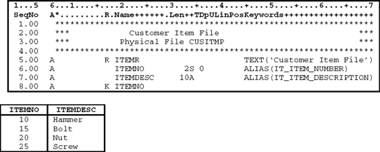
In the DDS shown in Figure 11.25, the customer file is paired with the customer order header file through the JOIN keyword on line 9.00 (CUSMSTP to CUSORDHDRP). The join fields are then specified with the JFLD keyword on line 10.00 (CUCNBR to OHCNBR). Next, the order header file (CUSORDHDRP) is joined with the order detail file (CUSORDDETP) on line 11.00, followed by the join field specification (OHORDERNO to ODORDERNO) on line 12.00. The same thing is done to join the order detail file with the item file (CUSORDDETP to CUSITMP). ODITEMNO and ITEMNO are used to join the customer order detail file with the customer item file. There are three groups of JOIN and JFLD keywords to join the four files. Sample data for this four-file logical join are shown in Figure 11.25.

JDFTVAL: File-level keyword that indicates that the system will provide default values for secondary file fields when a secondary record does not exist. Unless the DFT keyword is used in the physical file, the default value is blanks for character fields and zeros for numeric fields. The JDFTVAL keyword has no parameters.
JDUPSEQ: Record-level keyword that indicates a secondary file field-name used to sort records when duplicate join field values exist. By default, the sort order is ascending; descending can be specified. The format is
JDUPSEQ(sequencing-field-name *DESCEND).
JFILE: Record level keyword that identifies the files to be included in the join. The format is
JFILE(library-name/physical-file-name {..32}).
The first file-name specified is considered the primary file.
JFLD: Join-level keyword that indicates which fields are used to join the files. At least one JFLD keyword must be used on each join specification. The format is
JFLD(from-file-field-name to-file-field-name).
JOIN: Join-level keyword that identifies which pair of files is joined. The format is
JOIN(from-file to-file).
JREF: Field-level keyword used when the same field-name is used among the joined files and you need to indicate the file from which the field value is to be used. The format is
JREF(file-name or relative-file-number).
Simple logical files
Access path to a single physical file.
One record format is defined.
Can select records based on a comparison: VALUES, RANGE, and COMP.
Can select specific fields from the physical file.
Logical files are created the same way physical files are created except that they are defined as a file type of LF.
Logical files with multiple-record formats
Allow related records from two or more physical files.
Require key fields.
Contain two or more record formats.
A join logical file
Is a view of data from two or more physical files.
Contains only one record format.
Contains only one primary file. All others are considered secondary files.
1. Logical files contain data.
2. Data description specifications are used to define logical files.
3. A join logical file allows you to access data from two or more physical files.
4. The keyword UNIQUE must be specified with all logical files.
5. A logical file containing a multiple-record format creates a single logical record.
A(n) ___ logical file is based on one physical file.
A(n) ___ logical file contains two or more record formats.
A logical file defines a(n) ___ to the data stored in a physical file.
The ___ keyword associates the logical file with the physical file.
The ___ keyword indicates which fields are used to join the files.
The ___ keyword is used whenever there is a possibility that a secondary file record does not exist for a primary record.
The ___ keyword identifies the files to be included in the join.
The ___ keyword is used when the same field-name is used within the files that are being joined.
The ___ keyword allows the contents of a field to be compared to a specific value or values.
The ___ identifies which pair of files is to be joined.
Explain how a logical file creates an access path to data stored in a physical file.
Explain the concept of a simple logical file.
Explain how a logical file with multiple-record formats accesses data from two physical files.
Explain how a join logical file creates a single record format from two physical files.
Write a program that accesses the logical file in Figure 11.21 and prints a report as follows:

Write a program that accesses the logical file in Figure 11.25 and prints the following report:
