
Upon completion of this chapter, you should be able to
Describe the differences between an alphanumeric (character) field, zoned decimal field, and packed decimal field.
Explain the EBCDIC (Extended Binary Coded Decimal Interchange Code) representation for storing data.
Explain and demonstrate how Data Description Specifications (DDS) are used to describe files.
Describe the differences between arrival sequence and keyed sequence access paths.
Programming languages such as COBOL/400 provide the computer with the instructions to perform specific tasks. Normally, these instructions include accessing data. Data are unorganized raw facts.
To process data in an organized way, data areas are set aside in the computer's memory for fields, records, and files. A field is a group of storage positions reserved for a specific data item. For example, if a retail organization wanted to store data about their employees, it would probably want to include the following data items: employee number, store number, employee name, department number, hourly rate, hours worked, sales, and so on. Each data item describes one specific element of the employee and is stored as a field. Suppose an employee's number is 864955834. Enough storage positions would be set aside to store this value in the employee number field.
Examine the employee number field in Figure 1.1 and observe that the value 864955834 is stored in a storage area allocated to the employee number field. In addition, storage space is allocated to store the employee's last name. In this example, the value Hansen is stored in the employee last name field.

A record is a collection of related data fields stored as a unit. In our example, the fields for each employee are grouped together to form one employee record as shown in Figure 1.2. Within each employee record is specific data relevant to one employee in the organization.
Note that the record in Figure 1.2 is illustrated in table form for ease of reading. When stored in the computer, a record is stored as contiguous fields that usually do not include spaces between fields, periods, or commas. The symbol ^ represents an implied decimal point and is not stored in the record. Also, the negative sign shown in the Sales field is used to represent a negative value. We will see later in this chapter how negative values are stored in the computer.
A file or data file is a collection of records pertaining to a specific application. Figure 1.3 shows the first 15 records from the Employee Pay file. Each record represents data for one employee of the organization. A payroll file, accounts receivable file, inventory file, and sales file are examples of commonly used files in business applications.

In most instances, a computer application system will include several related files, which are referred to as a database. Thus, a database is defined as the overall collection of files in a computer application system that can be joined.
Data are grouped and stored in fields, records, files, and a database. Internally, data are stored differently depending upon the computer system used. Next, we discuss how data are stored within IBM midrange computers.
The two computer codes used for internal binary representation are EBCDIC and ASCII. Microcomputers and non-IBM computer vendors use ASCII. ASCII stands for American Standard Code for Information Interchange and is pronounced ass-key.
IBM midrange and mainframe computers use the EBCDIC coding system and is the only code illustrated in this book. EBCDIC, pronounced eb-ce-dick, stands for Extended Binary Coded Decimal Interchange Code and is used to represent letters, digits, the character blank, and special characters. The chart in
Figure 1.4 illustrates the EBCDIC codes for letters, numbers, and the character blank. It also displays the binary representation and hexadecimal (hex) codes used by the computer to represent EBCDIC codes. You need not memorize this chart, but you should be familiar with these methods for representing data.

Figure 1.4. EBCDIC codes for letters, numbers, character blank, and corresponding binary and hexadecimal codes.
There are times when it is necessary to display data as it is physically stored. However, it can be difficult to understand data in its binary form. Instead, each 8-bit EBCDIC byte is converted to a two-character hexadecimal value as shown in Figures 1.4 and 1.5.

Each 4-bit portion of a byte is represented by one hexadecimal character. Hexadecimal characters can range from 0 (all bits off = 0000) to F (all 4 bits on = 1111). Thus, the full range of 4-bit binary combinations and their hexadecimal characters is shown in Figure 1.5.
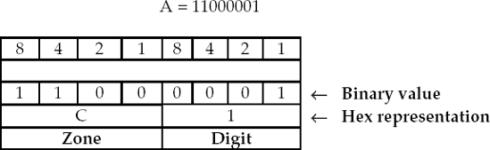
Figure 1.6 illustrates the binary and hexadecimal (hex) representation for the capital letter A. In EBCDIC, each storage position or byte consists of eight bits (binary digits). These eight bits are broken into two 4-bit segments: the high-order four bits are used to specify the zone portion and the low-order four bits are used to specify the digit portion.
The four high-order zone bits are used to indicate whether the value stored in the byte is a letter, positive number, negative number, or special character. The four low-order digit bits are used to represent the numbers 0 through 9. Examine Figure 1.4 and observe that 1100 in the zone bits indicates that the value of the byte is one of the uppercase letters A through I. If 1100 appears in the four zone bits, the digit bits then will indicate which specific letter from A through I is being represented. The digit bits can represent 0 through 9 as 0000, 0001, 0010, 0011, . . . 1001.
There are several different formats used to internally store data within the AS/400 and iSeries Servers. The method used to represent data internally depends upon the type of processing to be performed on the data. The method used to define numeric data also affects the program's efficiency. Fields can be classified as
Type | Description of Data |
|---|---|
A | Alphanumeric (Character) Numeric |
S | Zoned-decimal |
P | Packed-decimal |
B | Binary |
F | Floating-point |
L | Date |
T | Time |
Z | Timestamp |
H | Hexadecimal |
Only the most commonly used data types are illustrated in this book. Before we begin to consider the different data types, examine the record layout for the Employee Pay file called EMPPAYPF in Figure 1.7. This record description layout is used with examples throughout this book.
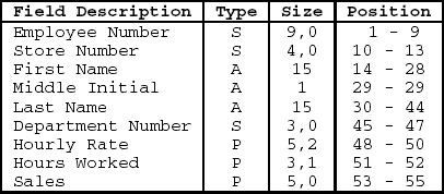
An alphanumeric field or character field is a field that contains any combination of letters, digits, and special characters such as $, %, @, or &. Simply, an alphanumeric field is a field that contains any printable characters. In Figure 1.7, the letter A in the Type column identifies alphanumeric fields. Thus, the first name, middle initial, and last name fields are defined as alphanumeric or character fields.
In this format a single position of storage, or byte, is used to store one character of data. Data defined as an alphanumeric (character) field cannot be used in arithmetic operations, even though the field may contain only numeric digits.
Each byte of an alphanumeric field is divided into two portions. The high-order, 4-bit zone portion and the low-order, 4-bit digit portion. The following shows how a 1-byte alphanumeric field containing the value J is represented in EBCDIC:
J = 1101 0001
Hex value Binary value
Zone | Digit |
|---|---|
D | 1 |
1101 | 0001 |
1 byte of alphanumeric data containing the value J
A numeric field is a field that contains the numeric digits 0 through 9 only. There are two considerations when defining numeric fields:
If a field is to be used in an arithmetic operation, it must be defined as a numeric field.
Fields such as employee number, ZIP code, and part number will probably not be used in arithmetic operations but contain numeric digits only. Thus, these fields could be defined as character fields or numeric fields. However, for data integrity in a database application it is recommended that all fields that contain numeric digits be defined as numeric fields regardless of how they are processed.
There are two primary methods for defining numeric data: zoned decimal and packed decimal. We discuss these data types next.
A zoned decimal field stores one numeric digit in each byte of storage. Fields stored in zoned decimal format can be up to 15 bytes in length. In Figure 1.7, the letter S in the Type column identifies zoned decimal fields. The letter S means signed, indicating that the field contains a positive or negative sign. Thus, the employee number, store number, and department number are zoned decimal fields.
Internally, the computer stores character and zoned decimal fields in the same format. Each byte of a zoned decimal field is divided into two portions: the high-order, 4-bit zone portion and the low-order, 4-bit digit portion.
The following shows how a 1-byte zoned decimal field containing the value 5 is represented in EBCDIC:
5 = 1111 0101
Hex value Binary value
Zone | Digit |
|---|---|
F | 5 |
1111 | 0101 |
1 byte of zoned decimal data containing the numeric value 5
Figure 1.8 illustrates a 5-byte zoned decimal field in which each byte represents one number or digit. Thus, it takes five bytes to represent the number 68255 in zoned decimal format since 68255 consists of five bytes.

The low-order or rightmost byte of a zoned decimal field indicates whether the field is positive or negative; all other zone portions in the field are ignored.
The sign of a zoned decimal field can be represented as positive or negative as shown in Figure 1.9.

For zoned decimal fields, each byte stores one digit, where the zone portion is equivalent to "all bits on" and the digit portion is the binary equivalent of one of the decimal numbers 0 to 9. The zone portion of the rightmost byte of zoned decimal fields contains the sign for the field.
There is a method that can be utilized where the zone portion is stripped from each byte (except for the low-order byte) so digits can be packed two per byte. In this way, the zone portion of each byte can be used to represent another digit.
Thus, two digits are represented in a single byte that saves space. This technique is called packing, and fields stored in this format are in packed decimal format.
Arithmetic operations can be executed on data when they are stored in any of the numeric data types. However, if a numeric field is not in packed decimal format, it is converted to packed decimal format before any computations are performed. If numeric fields to be used in arithmetic are defined in packed decimal format by the software developer, then this will result in a more efficient program.
Tip
PROGRAMMING TIP
IBM midrange and mainframe computers execute arithmetic operations in packed decimal format. Therefore, it is recommended that numeric fields being used in arithmetic operations be defined as packed decimal format. This saves CPU time when the arithmetic operations are executed.
Fields stored in packed decimal format can be up to eight bytes (15 digits) in length. In the record description in Figure 1.7, the letter P in the Type column identifies packed decimal fields. Thus, the hourly rate, hours worked, and sales fields are defined as packed decimal.
Consider Figure 1.10 to compare zoned decimal and packed decimal formats to see the result packing has on a field.
When a numeric field is packed:
Two numeric digits are stored in each byte of the packed decimal field, except for the rightmost byte that also contains the sign.
The values in the zone and digit portions of the low-order or rightmost byte are switched. This designates the field as a packed field. The low-order four bits (digit portion) of the rightmost byte of a packed field contain the sign (F = positive, D = negative).
All other zones are stripped, and two digits are packed into a single byte.
Consider the number 68254 in Example 1 of Figure 1.10. When a five-digit number is stored in zoned decimal format it occupies five storage positions or bytes. However, when stored in packed decimal format, it occupies three storage positions or bytes. This occurs because the zone portion of each byte (except the rightmost one) is removed, thereby permitting each byte to hold two digits. The low-order or rightmost byte contains only one digit since it also contains the sign of the field. In the zoned decimal field, the "F" in the zone portion of the rightmost byte represents a positive sign. In the packed decimal field, the sign is placed in the digit portion of the rightmost byte.
When a file contains a large number of numeric fields, using the packed decimal format saves considerable space and transfer time. For example, if a field consisting of seven bytes in zoned decimal format is converted to packed decimal format in a file of 100,000 records, 300,000 bytes of disk space is saved.

Example 2 in Figure 1.10 illustrates how a negative number is represented in zoned decimal and packed decimal formats. Notice in both formats that the negative sign is represented with a hexadecimal value D (1101). In the zoned decimal field, the "D" in the zone portion of the rightmost byte represents a
negative sign. In the packed decimal field, the negative sign (D) is placed in the digit portion of the rightmost byte.
Example 3, the number 835674 occupies an even number of bytes (six bytes) when stored in the zoned decimal format. When converted to packed decimal format it requires four bytes. The computer must complete the packing operation by adding four zero bits to complete or fill up the high-order byte. This occurs whenever the zoned decimal field contains an even number of bytes, as in 835674 (six bytes).
Tip
PROGRMMING TIP
It is recommended that when establishing a packed field, it should be defined as containing an odd number of digits. This eliminates the need for the operating system to zero-fill the high-order byte and allows the field to contain a larger value without requiring additional storage.
When converting a zoned decimal field to a packed decimal field, compute as follows:
Divide the number of digits in the zoned decimal field by 2.
If there is a decimal remainder of .5, drop it (round down).
Add 1 to the result.
Example 1
Convert a five-digit zoned decimal field containing 79645 to packed decimal format.
Divide 5 by 2; 2.5 is the quotient.
Round down to 2.
Add 1.
Result: Three bytes are needed for the packed field.
Example 2
Convert a six-digit zoned decimal field containing 937562 to packed decimal format:
Divide by 2; 3 is the quotient.
Add 1.
Result: Four bytes are needed for the packed field.
Note: Since 6 is an even number, the high-order four bits are zero-filled. Therefore, it is best to define this field as containing seven digits.
When converting a packed decimal field to a zoned decimal field, compute as follows:
Multiply the number of bytes in the packed decimal field by 2.
Subtract 1 from the result of the multiplication.
Example 1
Convert a three-byte packed decimal field containing the number 59759 to zoned decimal format.
Multiply 3 by 2.
Subtract 1.
Result: Five bytes are needed for the zoned decimal field.
Example 2
Convert a four-byte packed field containing the number 9407541 to zoned decimal format.
Multiply 4 by 2.
Subtract 1.
Result: Seven bytes needed for the zoned decimal field.
If data are entered in zoned decimal format and an arithmetic operation such as addition is specified, the computer must first pack the field, execute the add operation, and then unpack the field again. These conversions are performed automatically by the operating system and take additional processing time. Thus, it is recommended that numeric fields that are used in arithmetic operations be defined as packed decimal fields.
To print or display numeric fields in a readable form, they must be in zoned decimal format. Since packed decimal data are not in a readable form, fields specified as output fields to a print file should never be defined in the packed decimal format.
When moving a packed field to a zoned decimal field the computer automatically unpacks the sending field into the receiving field. In this way, packed fields stored on disk are converted to zoned decimal format so they can be printed in readable form.
Let us consider the data record in Figure 1.11 to demonstrate how data are represented internally in character, zoned decimal, and packed decimal formats.

The actual data record in Figure 1.12 shows both the hexadecimal and character representations to represent internal EBCDIC codes.
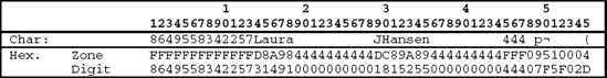
Note the following:
Blanks are represented as hexadecimal 40. When a value is stored in a character field, the unused portion is padded with blanks, as shown in the first and last name fields.
The negative sign in the packed sales field is represented with the value D in the low-order position of the byte (position 55).
Examine Figure 1.12 and observe the unusual character representations in positions 48 through 55. These positions represent three packed decimal fields: the hourly rate field in positions 48-50, the hours worked field in positions 51-52, and the sales field in positions 53–55. These fields are packed fields and contain two digits per byte except for the last byte, which contains the sign (F = positive or D = negative). No valid characters are shown for these three fields since the individual bytes contain two digits and thus are not represented by valid characters.
Let us consider position 49 to determine why the characters are displayed this way. The lowercase letter p is indicated in position 49. In position 49, the values 9 and 7 are packed into one byte. The binary representation for this single byte is 1111 1001 or 97. Refer back to Figure 1.4 and observe that the binary representation of 1001 0111 represents the lowercase letter p. So, as the system displays the data for the record, it examines each byte independently, not knowing that this field is packed. If a byte of data is equivalent to a valid character, that character is displayed. Thus, the lowercase letter p appears above the one byte of packed data that contains the values 9 and 7.
A date field is a field that contains a valid date. The letter L is used to identify a field as a date field. Date fields have a predetermined size of ten bytes and a predetermined format based on the internal format used in the application. Therefore, no data type or length is specified for date fields.
The default internal format for date fields is *ISO. ISO stands for International Standards Organization. When defined as an *ISO data type, the date field is defined as a ten byte field using the format yyyy-mm-dd.
The *ISO default internal format can be overridden by the definition specification keyword DATFMT. For example, the format of a date field can be changed to the *USA (IBM USA Standard) by specifying the DATFMT *USA keyword. By using this format, the date is internally stored in the format mm/dd/yyyy.
Two types of data files can be defined on the system: physical files and logical files. A physical file is a file that actually contains data records.
The relational database also supports the concept of a view in the form of a logical file. A logical file is a file that does not contain data and is basically a user's picture or view of the database. Logical files are covered in detail in Chapter 11.
Physical and logical files use access paths to access records in a file. The access path is the method used by the operating system to retrieve input records and write output records. The access path may be organized as arrival sequence (nonkeyed) or keyed sequence. Thus, records can be read from or written to a file based on: (1) an arrival sequence (nonkeyed) access path or (2) a keyed sequence access path. The access path for physical and logical files is stored with the actual file object.
An arrival sequence file uses an arrival sequence access path. This means that when a program retrieves records using arrival sequence, the records are sequentially retrieved from the physical file in the same sequence in which they were added to the file. This is known as the first-in, first-out (FIFO) principle. In other words, the first record presented to a program is the first record that was added to the file. So, an arrival sequence file is based on the actual order that records are stored in the physical file. This is also referred to as sequential access.
When new records are added to a physical file they are added to the end of the file. This means that the order of the records in the physical file is in no particular sequence.
With accessing records from an arrival sequence file, they are accessed sequentially. A specific record can be accessed only after first accessing all records that physically precede it. That is, for a program to read the 910th record in an arrival sequence file, it must first read past the first 909 records.
Suppose the Employee Pay file contained only the ten records shown in Figure 1.13 and that the file is stored in arrival sequence. Thus, employee 827392161 was the first record added to the file, employee 228725876 was the second record added to the file, 235235658 was the tenth record added to the file, and so on.
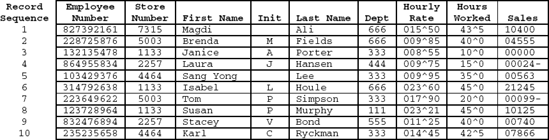
Figure 1.13 shows the order in which the records are stored in the file. Since the file is defined as arrival sequence, the records received by the program are in the same sequence as they are actually physically stored in the file, thus, first-in, first-out.
A keyed sequence file or keyed file uses a keyed sequence access path in which records are stored in sequence according to a key field. When creating a keyed file, the software developer must designate one or more key fields that uniquely identify each record in the file. The key field or fields may be located anywhere in the record, and they do not have to be contiguous within the record. In addition, the key field may be either alphanumeric or numeric. If the field is numeric, it should be defined as zoned decimal so that when records are displayed on the screen in character format the key field will be readable.
Figure 1.14 illustrates how the Employee Pay file appears as a keyed sequence file. The Employee Number field is the key field because it can be used to uniquely identify each record. When a keyed sequence file is created, the system establishes two files on disk:
The data file containing the actual data records. When a keyed file is created, the data file is established on disk and contains the physical data records stored in the sequence in which they are added to the file. In other words, the records are stored in exactly the same manner as arrival sequence files.
An index file containing the key field and a pointer field. The system uses the key field specified by the software developer to establish the index file. The system uses the index file to maintain the correct sequence of the records by sorting the index in order by the key field. The pointer field within the index contains the disk address of where each record is physically located in the data file.

The index file allows keyed files to be accessed randomly without accessing other records in the data file. This is accomplished by the system first searching for a match on the key field in the index. Then, the address stored in the pointer field is used to go directly to the physical disk address to obtain the desired record. Thus, to access a payroll record randomly, the user enters the Social Security number or employee number of the desired record. The system searches the sorted keys of the index file for the desired employee number. When a match
is found, the system uses the address stored in the pointer field to retrieve the physical record from disk. This is very useful for interactive processing when users need to enter key fields that are not ordinarily entered in sequence.
Once the address of the disk record is obtained from the pointer field in the index file, the disk drive's access mechanism can move directly to the physical address on the disk where the record is located. It is not necessary to read sequentially past all the previous records in the file looking for the desired one.
The index on a disk is similar to a book's index with unique subjects (keys) and their corresponding page numbers (addresses). There would be two ways to find a topic in the book. One method would be to read the book sequentially, from the beginning, until that topic is found, but this would be very time-consuming and inefficient. The best method would be to look up the topic in the index, find the corresponding page number, and go directly to that page. This is precisely how records are accessed on a disk file that has an index.
As noted, when a keyed file is created a key file or index is created in addition to the data file. As shown in Figure 1.14, each record in the key file or index contains two fields:
The key field
A pointer to the associated data record in the data file of the keyed sequence file.
The first field in each record of the key file or index contains the value of the key field of the associated record in the data file. For a payroll file, the key field may be an employee number or Social Security number; for an inventory file, the key field may be product number; for an accounts receivable file, the key field may be Customer Number.
The second field, the pointer, is a field containing the location (actual physical disk address) of the record in the data file that is identified by the key field.
When a physical file is created, key fields (indexes) provide the sequence in which records are retrieved from the file. When records are added to a keyed physical file, they are added to the end of the file. At the same time, the index file is updated with a record containing the key field and pointer that contains the record address of that record in the data file. The system places the new index records in their proper sorted positions in the index files and maintains the proper order by key field regardless of the physical address of the disk records in the data file. This permits random access of records in the file. So while the physical file itself is in arrival sequence, not in order by any set of field values, the index files effectively provide such orderings.
As noted, the records in the index file are stored and maintained in sequence according to the key field. During processing, record retrieval from the keyed file is performed by the system using the key file in a procedure that is completely transparent to the program. The data file and the index file may be thought of as one file.
Figure 1.14 shows how a program that defines the file as a keyed file would receive the same 10 records, illustrated earlier for the arrival sequence file. Note that the employee numbers (key field) are maintained in sequence within the key or index file.
Unlike arrival sequence, where records can only be accessed sequentially, keyed sequence files allow several methods of file access:
Sequentially in arrival sequence order (first-in, first-out) by ignoring the values in the key field.
Sequentially in keyed sequence order based on the value of the key field.
Randomly in any sequence based on the value of the key field.
Randomly in any sequence based on the relative record number.
Figure 1.15 illustrates the procedure for creating a physical file. Once the record description layout for the physical file has been determined, the format of the physical file is written on Data Description Specifications (DDS) forms. The software developer then uses CODE/400 or another editor to enter the Data Description Specifications into a Source Physical File, usually called QDDSSRC. When defining the physical file to the system, the Type field must be specified as PF for physical file. In this way, the system knows which type of object to create when the source DDS is compiled.

Once the source DDS are entered, the Create Physical File (CRTPF) command is used to compile the source DDS into a file object. Remember, as with all other objects, the compiled physical file is stored in a library. After the file is compiled into a file object, data can be entered or modified in the file.
Since PF is designated as the Type when the source is entered, the system knows what type of object to create when the DDS are compiled. The system stores the file description and record and field attributes with the file object and thus can control what functions may be performed on the file object.
Once the DDS for a physical file is compiled into a file object, computer programs can reference them. The record and field attributes of a physical file can be included directly into a program by defining the file as an externally described file where the record and field definitions are specified external to the program.
In summary, the steps for creating a physical file are
Determine the record format for the physical file.
Write the Data Descriptions Specifications (DDS) for the physical file.
Enter the DDS source member using CODE/400 or other editor.
Compile the DDS source member into a physical file object, correcting syntax errors when required.
Let us use a case study to consider each step in detail.
The purpose of this case problem is to illustrate how to
Create and enter DDS for the Employee Pay file (EMPPAYPF) source member.
Compile the EMPPAYPF source member into a file object.
Use DFU to enter data into the EMPPAYPF physical file.
Display the record contents of the file.
A physical file contains only one record format with each data record having the same record length, referred to as fixed-length records, and containing the same fields in the same order.
The record format for a physical file must be determined before the actual file can be created. Consider the record format for the Employee Pay file in Figure 1.16. This file is used to illustrate how to define arrival sequence (non-keyed) and keyed sequence physical files.

Data Description Specifications such as those in Figure 1.17 define record formats in physical and logical files. This includes defining the characteristics of fields including field names, size of fields, the type of data to be stored in the fields, valid values that fields can contain, and so on. In addition, DDS can contain column headings and other textual information, range boundaries for
numeric fields, validity checking specifications, and other characteristics or attributes about the fields.
When source DDS are entered for a physical file, the source type must be specified as PF (physical file). When the source DDS are compiled into a file object, the computer system knows what type of object to create from the type PF specification. In this way, the access path of a physical file along with the file description and record and field attributes are stored with the file object, independently of any programs that might use it. Thus, when the file object is used, the system knows which functions can be performed on the object based on the object's type of PF.
When a software developer wants to access a file in a program, reference to the external file object is specified in the program. At program compile time, the system copies the pertinent information about the file and fields from the file object into the program and compiles it with the rest of the program.
Physical files are not dynamic. If the DDS format of a file is changed, the change is not dynamically duplicated in all of the programs that refer to the file. Every program affected by the change still needs to be recompiled.
Let us consider the Data Description Specifications for the Employee Pay physical file called EMPPAYPF. First, we examine the DDS in Figure 1.17 that defines the Employee Pay file as an arrival sequence (nonkeyed) physical file. Then, we discuss the specifications that are necessary to define the file as a keyed file.
The record description in a physical file is called a record format. As noted earlier, there can be only one record format in a physical file.

All Data Description Specifications have the letter A in position 6.
Lines 1.005.00: Comment lines are indicated by an * in the Comment field (position 7). These comment lines do not become part of the file object when the source DDS are compiled.
The left side of the DDS (positions 7 through 44) has specific positions for specific functions. Positions 45–80 are the keyword area. The keyword area is more free-form and allows a wide variety of entries. Keywords include TEXT, COLHDG (column heading), VALUE, which identifies the valid values that are permitted in a field, and RANGE, which sets the upper and lower boundaries of values that are permitted in a field.
The DDS for physical files contain four levels. The first level, called file level, appears at the beginning of the DDS and defines characteristics that apply to the
entire physical file. The record level follows the file level and is used to describe characteristics that apply to the entire record format of the physical file. Next follows the field level, which is used to define each field in the record format and describe its attributes. For keyed files, the key field level follows the field level and defines the key fields.
Each level of the EMPPAYPF arrival sequence physical file is described below.
File Level
There are no file level specifications for this file. File level specifications are specified first before the record format level specifications.
Record Level (Line 6.00)
The description of the records in a physical file is called a record format. There can be only one record format in a physical file.
Line 6.00: This is the record-format line that assigns a unique name to the record format. The letter R specified in the Name Type field (position 17) indicates that this line is defining the record format name. The name of the record, EMPPAYR, is left-justified in the Name field (positions 19–28).
Record names can be up to 10 characters in length and must begin with an alphabetic character or one of the special characters @, $, and #. The remaining characters in the record name may be A-Z, 0–9, @, $, #, and the underscore (_) character. Embedded blanks are not allowed. Notice that the record name differs from the file-name to meet a requirement that all file and record names must be unique in programs.
Note that only one record format may be defined for a physical file. This is a database rule for physical files. As a result, each record in a physical file is the same length and contains the same fields that are the same length and type and in the same sequence.
TEXT Keyword: A text description (TEXT keyword) is provided to describe the record. It also can be used to describe fields. The TEXT keyword is used for documentation only.
Field Level (Lines 7.00–15.00)
Line 7.00: The Employee Number, called EMPLOYEENO, is left-justified in the Name field (positions 19–28). The rules for forming field names are the same as those for record names explained on line 6 above.
The 9 right-justified in the Length field (positions 30–34) indicates that the field contains nine digits. The 0 right-justified in the Decimal Positions field (positions 36–37) indicates that the field has zero decimal positions. Remember, the number of decimal positions must be entered for all numeric fields even if the number of decimal positions is zero. When an entry is specified in the Decimal Positions field, the field is automatically defined as numeric. The default is that if the decimal positions entry is omitted, that is, columns 36–37 are blank, the field is defined as a character (alphanumeric) field.
The letter S in the Data Type field (position 35) indicates that the field is signed zoned-decimal numeric. Thus, the field will occupy nine bytes of storage in the record.
ALIAS Keyword: Physical files allow a data field to have an alternative (ALIAS) name of up to 30 characters. When the ALIAS keyword is used, the ALIAS name,
EP_EMPLOYEE_NUMBER in this instance, is copied to the program instead of the field name EMPLOYEENO in the Name field (positions 19–28).
The underscores (_) are converted to hyphens (-) when the ALIAS name is copied into a COBOL/400 program.
Default Data Types (position 35): The Data Type field (position 35) is optional. If specified, a field is defined as follows:
| A Alphanumeric (character) |
| S Zoned decimal |
| P Packed decimal |
If the Data Type field (position 35) is blank and the Decimal Positions field (positions 36–37) is blank, the default field type is A for alphanumeric (character).
If the Data Type field (position 35) is blank and the Decimal Positions field (positions 36–37) is not blank, that is, it contains a valid numeric number, then the default field type is P for packed decimal.
Tip
PROGRAMMING TIP
We recommend that a data type be specified for all fields. This will help novice software developers in debugging the DDS since there will be no confusion as to what the data type really is. Also, specifying the data type provides instant documentation.
Line 8.00: The Store Number field, STORENO, is defined as a 4-byte zoned-decimal field with zero decimal positions. The 4 in the Length field (positions 30–34) indicates four digits in length and the S in the Data Type field (position 35) indicates that the data type is zoned decimal numeric. Thus, the field will occupy four byes in storage. The 0 in the Decimal Positions field (positions 36–37) indicates zero decimal positions.
The ALIAS name of EP_STORE_NUMBER has been assigned to this field.
Line 9.00: The First Name field, FIRSTNAME, is defined as a 15-byte alphanumeric (character) field (A in Data Type field, position 35). An alias name of EP_FIRST_NAME is assigned using the ALIAS keyword in positions 45–72.
Line 10.00: The Middle Initial field, MIDDLEINIT, is defined as a 1-byte alphanumeric field (A in Data Type field, position 35). An alternative name of EP_MIDDLE_INITIAL is assigned using the ALIAS keyword.
Line 11.00: The Last Name field, LASTNAME, is defined as a 15-byte alphanumeric field (A in Data Type field, position 35). An alternative name of EP_LAST_NAME is assigned using the ALIAS keyword.
Line 12.00: The Department field, DEPARTMENT, is defined as a three digit zoned decimal field (S in Data Type field, position 35) with no decimal positions. An alternative name of EP_DEPARTMENT is assigned using the ALIAS keyword.
Line 13.00: The Hourly Rate field, HOURLYRATE, is defined as a five-digit packed field with two decimals (2 in the Decimal Positions field, positions 36–37). The letter P in the Data Type field (position 35) indicates that the data type is packed decimal. An alternative name of EP_HOURLY_RATE is assigned using the ALIAS keyword.
Although this field is defined as packed decimal, the unpacked size of the field is specified in the Length field. The HOURLYRATE field will hold five digits
but is packed into three bytes of storage in the record. Thus, the hourly rate field is stored in positions 48 through 50 of the record.
If the hourly rate of an employee is 28.45, then 0 is placed in the leftmost or high-order position of the field. Thus, if the hourly rate is 28.40, the rate is stored as 02845 and interpreted as 028.45. Numeric data is always right-justified in this way.
The decimal point is not stored in the record with the data, since it would waste a storage position. We will see that COBOL uses implied decimal points, represented as the letter V, to define numbers with decimal components.
Line 14.00: The Hours Worked field, HRSWORKED, is defined as a three-digit packed field with one decimal (1 in the Decimal Positions field, positions 36–37). The letter P in the Data Type field (position 35) indicates that the data type is packed decimal. An alternative name of EP_HOURS_WORKED is assigned using the ALIAS keyword.
Line 15.00: The Sales field, SALES, is defined as a five-digit packed field with zero decimals (0 in the Decimal Positions field, positions 36–37). The letter P in the Data Type field (position 35) indicates that the data type is packed decimal. An alternative name of EP_SALES is assigned using the ALIAS keyword.
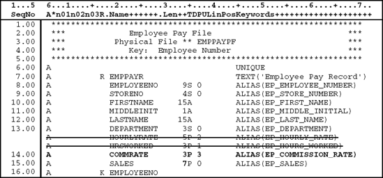
For keyed sequence files, the order in which records are retrieved from the file is based on the contents of the key fields defined in the DDS. Keyed sequence allows direct access to a record in a file through the value of its key fields and permits the sequential retrieval of the records of a file according to the values of the key fields. Let us consider the Data Description Specifications (DDS) that are necessary to define the Employee Pay file as a keyed file. Figure 1.18 shows the DDS source for the EMPPAYPF physical file described as a keyed file. There are two additional entries necessary to define this file as a keyed file. Both are highlighted in bold, and a description of the additional entries necessary for keyed sequence files follows the figure.

File Level (Line 6.00)
Line 6.00: The file level keyword UNIQUE specified in the keyword field (positions 45–80) indicates that the key field, Employee Number, is unique within the records. This means that every employee number within the file contains a different value. A run-time error will occur if a program tries to add a record to the file with a value in the Employee Number field that is equal to the Employee Number of an existing record.
This line does not tell the system which field is the key field. It just states that the key field must be unique for each record. If UNIQUE were omitted for a keyed sequence file, duplicate keys would be allowed. This means that the file could contain several records in which the Employee Number field contained the same value, thus making it impossible to uniquely identify a specific record.
Key Field Level (Line 17.00)
The key field level of the DDS must follow the field level.
Line 17.00: The letter K in the Name Type field (position 17) indicates that the field specified in the Name field (positions 19–28) is the key field for this keyed sequence file. Thus, EMPLOYEENO is the key field.
Since EMPLOYEENO is defined in the field level section, its attributes (length, data type, and decimal positions) are already specified and are not specified again in the key field level.
Any number of fields may be specified as key fields, but they must be defined previously in the field level section of the record format. Also, when more than one field is defined as a key field, the fields do not have to be contiguous within the record.
If more than one key field is specified, the computer system will maintain the sequence of the keys (indexes) by sorting them into the correct sequence. The key fields are sorted from top to bottom. That is, the first key field listed is the high-order key or primary sort field and the last key field listed is the low-order sort field.
To write programs that access the Employee Pay file, you need to refer to the DDS of the physical file EMPPAYPF so you can use the correct field names in describing the output report file. The ALIAS names are assigned to the fields in the DDS to standardize names for the fields in this file and are used for all programs that access this file as an externally described file. The prefix EP-(Employee Pay) is used to indicate that these fields are part of the Employee Pay File.
Creating the source DDS for a file does not create the actual file. Executing the Create command CRTPF (CReaTe Physical File) creates a physical file object (*FILE).
The CRTPF command will invoke the compiler that will inspect the DDS source statements for correct syntax. If the DDS does not contain any errors, a listing of the file layout is printed and the file object created.
If errors are found, the compiler will produce a listing of the DDS source along with a description of the errors. The errors must be corrected in the source DDS and the CRTPF command run again. This cycle must be repeated until all errors have been corrected and the CRTPF command produces a file object from the source DDS.
When the CRTPF command is submitted, the system checks to see if a file already exists in the library specified in the CRTPF command. If a file exists, the
system will prompt with a request to delete the old object. If you respond with Y for yes, the old object is deleted and the CRTPF command creates a new object. In doing so, all data in the old file object are deleted. Thus, it is important to remember that if a physical file exists and data have been entered into the file, the data will be lost if a software developer changes the source DDS and recompiles the data into a new object. To prevent this from happening, use the CHGPF command discussed later in this chapter. Also, the data could be copied to a file of a different name before the new object is created. Then, the data can be copied back to the new object after the Create command is run. Remember to exercise caution when recompiling source DDS for a physical file that already contains data.
The Create command that creates the physical file for the EMPPAYPF file is:
CRTPF FILE (userLIB/EMPPAYPF) SRCFILE (userLIB/QDDSSRC)
SRCMBR (*FILE) TEXT ('Employee Pay File')
The FILE parameter supplies the name of the physical file that is being created and the library in which it will be stored. In this example, the physical file EMPPAYPF is created in userLIB, where userLIB is your library. The SRCFILE (Source File) parameter supplies the location of the member containing the DDS source. In this example, the system will search the QDDSSRC source physical file in userLIB for the DDS source. The TEXT parameter provides a method of providing up to 50 characters of descriptive text about the file.
The source DDS can also be compiled into a file object from the PDM Work with Members screen. Once the source DDS are completed and saved, option 14 can be entered in the Option column beside the name of the DDS you wish to compile into an object. Option 14 will cause the system to create the CRTPF command for you and submit the command to batch.
The Display File Field Description (DSPFFD) command is used to display the description of the file and attributes of the record format and fields contained in the record format. To execute this command
Enter DSPFFD on any command line.
Press F4 for the fill-in-the-blanks prompt screen.
Enter EMPPAYPF in the File field and userLIB in the Library field, where userLIB is your library name.
Press Enter.
The Display File Field Description command displays several screens containing information relating to the file, record format, and fields. Figure 1.19 provides this information about the EMPPAYPF file. The screens displayed by the DSPFFD have been grouped here for readability.


Initially, after the source DDS for a physical file have been created and compiled into a file object, the file will not contain any records. In other words, the file exists as an object with a file description and record and field attributes but no data records.
There are many methods by which data records can be entered into a physical file. For example, computer programs can add records to a physical file, as we will see later in the book. For now, let us consider how we might get records into the EMPPAYPF file so we can run and test our programs.
Data File Utility (DFU) is an IBM utility product that provides one method of entering test data into a physical file. DFU has several options for maintaining physical files. We will consider only the DFU option that allows the temporary update of a physical file.
To use DFU to enter the data in Figure 1.20 into the EMPPAYPF physical file, complete the following steps:
Enter STRDFU on a command line
Press Enter.
Enter the number 5 to select option 5, Update data using temporary program.
Enter emppaypf into the Data file field
Enter userLIB into the Library field, where userLIB is your library.
Press Enter.
DFU will create a temporary program that allows data to be entered into the specified file. This temporary program is created using the attributes stored with the specified file object. Data records can now be entered.

After the data have been entered into the physical file, the records may be displayed to confirm the contents of the file. One method to accomplish this is with the Display Physical File Member (DSPPFM) command. To execute the DSPPFM command
Enter DSPPFM on any command line.
Press F4 for the fill-in-the-blanks prompt screen.
Enter EMPPAYPF in the File field and userLIB in the Library field, where userLIB is your library name.
Press Enter.
Figure 1.21 shows the result of executing the DSPPFM for the EMPPAYPF file. Note that the packed fields in positions 48 through 55 are unreadable. This is because each byte consists of two digits of data that cannot be translated into character or hexadecimal form.
Another method that can be used to display the records of a file is the Copy File (CPYF) command. One advantage of this command is that each record is displayed with both the character and hexadecimal representations. To execute the CPYF command
Enter CPYF on any command line.
Press F4 for the fill-in-the-blanks prompt screen.
Fill-in the fields as follows:
Enter EMPPAYPF in the From file field.
Press Field Exit or Tab.
Enter userLIB in the Library field, where userLIB is you library name.
Press Field Exit or Tab.
Enter *PRINT in the To file field so that you can print or display the output of the command.
Press Tab SIX times.
Enter *HEX in the Print format field so that character and hexadecimal values are displayed.
Press Field Exit to exit from the Print format field and clear the remainder of the field.
Press Enter.
Once the CPYF command has been completed, you need to look at the spool file for the output.
Enter WRKOUTQ userOUTQ on any command line, where userOUTQ is your output queue.
Enter 5 in the Option column beside the spool file from this CPYF command.
Press Enter.
Figure 1.22 shows the result of executing the CPYF for the EMPPAYPF file. As in the DSPPFM command, the packed fields are not readable in character format. The hexadecimal value indicates the actual values stored in all fields, including the packed fields. Understanding how to read the hexadecimal values can be of great assistance when debugging programs that change or update data records in a file. If you need to verify the actual values of data in a file, especially packed decimal fields, displaying the hexadecimal value will tell you the values of all fields. Also, the hexadecimal value is one of the best ways to verify that a negative numeric packed decimal field contains a negative sign. Records that contain negative Sales will contain a D (negative) for the sign in the low-order rightmost byte.
Note that the records are displayed in keyed sequence. The RCDNBR field indicates the physical location of the record in the data file.


There are times when after a physical file is created and data have been entered, the software developer realizes that a change to the physical file is necessary. Such changes could include changing the size of a field or adding a new field to the physical file. For example, a personnel file containing data about the employees could be in production for many years when the personnel manager decides to add a new deduction field for the employee sick fund. In this case, the DDS for the personnel file needs to be changed without affecting the existing data in the file.
When the structure of a physical file changes, the CHGPF (Change Physical File) command is used to recompile the file without loosing the data that are currently stored in the data file. The CHGPF command saves the original data and transfers the data to the new file. In addition, logical files are recompiled based on the newly modified physical file. To illustrate this, let us consider our Employee Pay file.
In the original DDS for the Employee Pay File in Figure 1.23, the company allows for sales up to but not including one hundred thousand dollars ($99,999). Therefore, the sales field in the physical file is five digits long with zero decimal places. This is adequate until changes occur. Maybe inflation causes the company to raise the price of its products, which raises sales beyond $100,000, or the company decides to start selling a different line of products that sell for much more than the old product line. When this happens, a software developer must change the sales field to allow for at least six or more digits.

Now, suppose the Best Deal Stores Company needs to make changes to the Employee Pay file. First, the company has decided to reimburse employees based on a commission percent of sales rather than an hourly rate based on hours. Therefore, a new commission rate field needs to be added to the file. In addition, since the hourly rate and hours worked fields will no longer be used, they need to be removed from the file. Commission rate is a three-digit field represented as .999.
Second, the size of the sales field needs to be expanded from five digits to seven digits. The new sales field will contain zero decimal positions.
Figure 1.24 shows the modified DDS for the Employee Pay file.
To change the EMPPAYPF file layout, the following CL command is executed:
CHGPF | FILE COBOL2DLIB/EMPPAYPF) | + |
SRCFILE (COBOL2DLIB/QDDSSRC) | + | |
SRCMBR(EMPPAYPF) | + | |
DLTDEPLF (*YES) |
When the DDS are changed to reduce a field's size or to remove a field and the CHGPF command is executed, the system sends the following error message:
CPA32B2 Change of file EMPPAYPF may cause data to be lost (C I)
This message appears because the hourly rate and hours worked fields are not included in the new DDS. Entering I (Ignore) tells the system to continue executing the CHGPF command. When the CHGPF command completes, the Employee Pay file EMPPAYPF has the new format and the data have been copied to it. The data are copied by field name.
The DLTDEPLF parameter is specified so that all depended logical file objects are deleted before the physical file is recompiled.
There are some things to remember about the CHGPF command:
If the name of a field is changed, that field's data are not retained in the new file.
New fields are loaded with a default value. Numeric fields default to zero, and alphanumeric fields default to spaces.
A field's data type cannot be changed. If a field's data type is changed, an error message (CPD32CB Field XXXXXXXXXX cannot be changed for file XXXXXXXXXX in XXXXXXXXXX.) is displayed, and the CHGPF terminates.
Changing a file's record layout does not directly affect the programs using the file. All programs accessing the file must be recompiled before they can access the new version of the file. If a program tries to access the new file before it is compiled, the system issues an error that indicates the record format of the file is not the same as when the program was originally compiled.
Note: It is good practice to make a backup copy of a data file before changing its record layout. If for some reason something goes wrong and the data file is lost, the file can be recovered from the backup copy. Never risk losing data.
The most commonly used data types used on iSeries Servers are
Data Type | Characteristics | Types Of Data |
|---|---|---|
Alphanumeric (Character) (A) | Stores one character in each byte of the field. | Can contain any combination of letters, digits, and special characters such as $, %, @, and &. |
Numeric: | Can contain the numeric digits 0 through 9 only. | |
Signed Zoned Decimal (S) | Stores one numeric digit in each byte. The sign of the field is stored in the low-order or rightmost byte. | |
Packed Decimal (P) | Two numeric digits are stored in each byte, except for the rightmost byte, which contains one digit and the sign of the field. |
Keyed sequence files can be summarized as follows:
Keyed sequence files can be processed either sequentially or randomly; they can also be processed both sequentially and randomly at the same time in the same program. That is, you may want to update a keyed sequence file randomly and then print a report sequentially, all in the same program.
New records are added to the end of a physical file. At the same time, records are added to the key file or index. The system maintains the key file or index in proper sequence so that records can be retrieved from the keyed sequence file in order of the key field.
The processing of a physical file defined as a keyed sequence file either randomly or sequentially is transparent to the program. When reading records from the file, you need only supply the key field and the system will locate the corresponding record.
Keyed sequence files offer faster access than arrival sequence files when the program is designed to read records in no particular order.
Access path
ALIAS
Arrival sequence
Copy File (CPYF)
Data Description Specifications
(DDS)
Data File Utility (DFU)
DB2/400
Display File Field Description (DSPFFD)
Display Physical File Member (DSPPFM)
Externally described files
Index
Key field
Key file
Keyed sequence
Logical file
Physical file (PF)
Pointer
Program-described files
Relational database model
1. The database management system used on the iSeries Server and AS/400 is the relational database model.
2. The iSeries Server uses the ASC II coding system for internal binary representation.
3. Records can be retrieved from an arrival sequence file by using the assigned key field.
4. When creating a physical file, the Type field must be specified as PF.
5. Data Description Specifications are used to define physical files.
6. If the length of a packed field is specified as 9 on the DDS, the field will occupy nine bytes of storage.
7. The DSPFFD command is used to view the data in a physical file.
8. The DSPPFM command displays the attributes of a file.
9. Alphanumeric and zoned decimal fields are represented in the same format in storage.
10. Source DDS is stored in a source physical file (source file).
When created, a keyed file establishes two files on disk: the ___ file and a separate ___ file.
The ___ field uniquely identifies each record in a keyed file.
The key file or index contains two fields: the ___ field(s) and a ___ to the physical data.
A database is a collection of ___ files for a given application that can be ___.
The iSeries Server and AS/400 use the ___ database model called ___.
In a(n) (arrival sequence/keyed) file, the records are processed in a first-in, first-out sequence.
In a(n) (arrival sequence/keyed) file, records can be accessed according to a specific field(s).
A (logical/physical) file contains data.
A quick method to enter data into a file or modify existing data in a file is to use the OS/400 utility ___.
The structure of DDS for a physical file is broken up into different levels. These levels include ___, ___, ___, and ___.
DSPFFD is an abbreviation for the ___ command.
DSPPFM is an abbreviation for the ___ command.
CPYF is an abbreviation for the ___ command.
In relational databases, records are often displayed as ___ in a table.
Keyed files can be processed either ___ or ___.
Explain how a physical file is created.
Explain the difference between program-described files and externally described files.
Explain the purpose of the DDS ALIAS keyword.
Using the following problem definition
Create the DDS for the Customer Transaction File.
Use DFU to enter sample test data into the file.
Record Description Layout for customer transaction file
Field Description
Type
Size
COBOL Field-name
First Name
A
9
CT-FIRST-NAME
Middle Initial
A
1
CT-MIDDLE-INITIAL
Last Name
A
15
CT-LAST-NAME
Date of Transaction (M/D/YY)
L
10
CT-DATE-OF-TRANSACTION
Transaction Amount
P
7,2
CT-TRANSACTION-AMOUNT
Using the following problem definition
Create the DDS for the Payroll Salary File named PAYSALPF.
Use DFU to enter sample test data into the file.
Record Description Layout for payroll salary file
Field Description
Type
Size
COBOL Field-name
Employee Number (K)
S
5,0
PS-EMPLOYEE-NUMBER
Employee Last Name
A
20
PS-EMPLOYEE-LAST-NAME
Employee First Name
A
12
PS-EMPLOYEE-FIRST-NAME
Territory Number
S
2,0
PS-TERRITORY-NUMBER
Office Number
S
2,0
PS-OFFICE-NUMBER
Annual Salary
P
7,0
PS-ANNUAL-SALARY
Social Security Number
S
9,0
PS-SOCIAL-SECURITY-NUMBER
Using the following problem definition
Create the DDS for the Customer Address File named CSTADDPF.
Use DFU to enter sample test data into the file.
Record Description Layout for customer address file
Field Description
Type
Size
COBOL Field-name
Customer First Name
A
15
CA-CUSTOMER-FIRST-NAME
Customer Middle Initial
A
1
CA-CUSTOMER-MIDDLE-INITIAL
Customer Last Name
A
20
CA-CUSTOMER-LAST-NAME
Street Address
A
20
CA-STREET-ADDRESS
City
A
15
CA-CITY
State
A
2
CA-STATE
Zip Code
S
5,0
CA-ZIP-CODE
Using the following problem definition
Create the DDS for the Customer Usage File named CSTUSGPF.
Use DFU to enter sample test data into the file.
Record Description Layout for customer usage file
Field Description
Type
Size
COBOL Field-name
Account Number (K)
S
5,0
CU-ACCOUNT-NUMBER
First Name
A
10
CU-FIRST-NAME
Last Name
A
15
CU-LAST-NAME
Street Address
A
20
CU-STREET-ADDRESS
Kilowatt Hours of Electricity Used
P
5,0
CU-HOURS-OF-ELECT-USED
Gas Used
P
5,0
CU-GAS-USED
Electricity Bill
P
5,2
CU-ELECTRICITY-BILL