
Chapter 4
Undirected Graph Template
The undirected graph is also a term from graph theory. An undirected graph is a set of nodes and a set of edges. Each edge connects two nodes (which may be the same). The nodes of an undirected graph can have any number of edges. Undirected graphs arise for applications with important topology or connectivity. For example, the network of members on the LinkedIn Web site is an undirected graph.
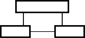
Figure 4.1 shows two examples of undirected graphs.

Sample undirected graphs. An undirected graph is a set of nodes and a set of edges that connect the nodes.
There are three templates for undirected graphs.
- Node and edge undirected graph. Regards nodes and edges as peers. Use as the default template when there are no edges that connect to the same node.
- Connection undirected graph. Promotes the connection between a node and an edge to an entity type. Use when there is data for the connection itself.
- Undirected graph changing over time. Stores variants of a node and edge undirected graph. A particular undirected graph can be extracted by specifying a time. Use when the history of an undirected graph must be recorded.
There is no undirected graph counterpart to the simple and structured templates of directed graphs. The simple counterpart violates the symmetry antipattern (see Chapter 8). The structured counterpart shares a similar flaw as it is not clear which end of an edge should be the parent and which should be the child. In principle, it would be possible to add time intervals to the connection template, but we have never seen a need for this in practice.
4.1 Node and Edge Undirected Graph Template
4.1.1 UML Template
Figure 4.2 shows the UML template for node and edge undirected graphs.

Node and edge undirected graph: UML template. Use as the default template when no edges connect to the same node.
A UDG (undirected graph) is a set of nodes and a set of edges that connect nodes. (Note: in an undirected graph all nodes do not have to be connected.) You need not show UDG in a use of the template. A Node is an entity type whose records are organized as an undirected graph. An Edge is a coupling between Nodes.
With this template the names of nodes and edges are globally unique. There is no context to provide an alternative approach to naming.
Figure 4.2 lacks the constraint that related nodes and edges must all belong to the same undirected graph. The template also cannot handle edges that connect twice to the same node (the “2” in Figure 4.2 refers to two different nodes); use the connection undirected graph if an edge connects twice to the same node.
4.1.2 IDEF1X Template
Figure 4.3 restates Figure 4.2 with the IDEF1X notation. The following are foreign keys: udgID references UDG, edgeID references Edge, and nodeID references Node. The “2” multiplicity in Figure 4.2 becomes “many” multiplicity in a database design.

4.1.3 SQL Queries
Figure 4.4 and Figure 4.5 show SQL queries for common traversals of the template. The colon prefix denotes variable values that must be provided for each query.


4.1.4 Sample Populated Tables
Figure 4.6 shows node and edge undirected graph tables populated with data. The values of the IDs are arbitrary, but internally consistent.

4.1.5 Examples
Undirected graphs occur only occasionally and when they occur, the node and edge template is often appropriate.
The LinkedIn Web site is popular for professional networking. Members can connect to other members and find those who are closely connected via intermediate colleagues. Such contacts can be useful for seeking employers, seeking employees, and sharing information. An undirected graph is the proper representation because there is a lack of direction in connections between members. It does not matter who initiated the contact; all that matters is that pairs of members are connected. Furthermore, it makes no sense for a member to connect to himself or herself. Thus the limitation of the node and edge template is not a problem.
Figure 4.7 shows a model for the LinkedIn network using the node and edge undirected graph template. The LinkedIn Web site manages extensive data about members that Figure 4.7 does not show as the emphasis is on the template.

4.2 Connection Undirected Graph Template
4.2.1 UML Template
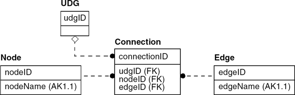
Figure 4.8 elaborates the node and edge template, promoting the connection between nodes and edges to an entity type. Figure 4.8, as stated, does not permit unconnected Nodes. You could add a relationship between UDG and Node if unconnected Nodes were important.

Connection undirected graph: UML template. Use when there is data for the connection itself or edges connect to the same node.
A UDG (undirected graph) is a set of nodes and a set of edges that connect nodes. You need not show UDG in a use of the template. A Node is an entity type whose records are organized as an undirected graph. An Edge is a coupling between Nodes. A Connection is the linking between a Node and an Edge.
With this template the names of nodes and edges are globally unique. There is no context to provide an alternative approach to naming.
Figure 4.8 lacks the constraint that related nodes and edges must all belong to the same undirected graph.
4.2.2 IDEF1X Template
Figure 4.9 restates Figure 4.8 with the IDEF1X notation. The following are foreign keys: udgID references UDG, nodeID references Node, and edgeID references Edge. The combination of nodeID + edgeID need not be unique for a Connection as a Node and Edge can connect twice.
4.2.3 SQL Queries
Figure 4.10 and Figure 4.11 show SQL queries for common traversals of the template. The colon prefix denotes variable values that must be provided for each query.

Connection undirected graph: SQL query. Find the edges that connect to a node and how often they connect.

Connection undirected graph: SQL query. Find the nodes for an edge and how often they connect.
4.2.4 Sample Populated Tables
Figure 4.12 and Figure 4.13 show connection undirected graph tables populated with data. The values of the IDs are arbitrary, but internally consistent.


4.2.5 Examples
Figure 4.14 illustrates the template. A manufacturing plant can have a variety of equipment that is connected by piping. For stress calculations, all that matters is that the equipment is connected. Stress calculations ensure that piping does not break under the load of forces such as wind and temperature changes.

4.3 Undirected Graph Changing over Time Template
This template adds time intervals to the Node and Edge entity types from Section 4.1.
4.3.1 UML Template
Figure 4.15 shows the template for the node and edge undirected graphs that change over time, extending the template in Figure 4.2. The template in Figure 4.15 cannot handle edges that connect twice to the same node.

Undirected graph changing over time: UML template. Use when history must be recorded and no edges connect to the same node.
A UDG (undirected graph) is a set of nodes and a set of edges that connect nodes. (Note: in an undirected graph all the nodes need not be connected.) You need not show UDG in a use of the template. A Node is an entity type whose records are organized as an undirected graph. An Edge is a coupling between Nodes.
With this template the names of nodes and edges are globally unique. There is no context to provide an alternative approach to naming.
4.3.2 IDEF1X Template
Figure 4.16 restates Figure 4.15 with the IDEF1X notation. The following are foreign keys: udgID references UDG, nodeID references Node, and edgeID references Edge. In Figure 4.16 the node name can change over time (three part candidate key—nodeName + effectiveDate + expirationDate), but the node name could also be invariant over time (candidate key of nodeName alone). Similarly the edge name could be invariant over time.

4.3.3 SQL Queries
Figure 4.17 and Figure 4.18 show SQL queries for common traversals of the template. The colon prefix denotes variable values that must be provided for each query. With this template an edge cannot connect twice to the same node, so there is no need to group nodes in Figure 4.18.


4.3.4 Sample Populated Tables
Figure 4.19 shows tables populated with data for the node and edge undirected graph changing over time. The values of the IDs are arbitrary, but internally consistent. A null effectiveDate means that a Node applies from the past. A null expirationDate means that a Node applies into the future.

4.3.5 Example
An extended model (Figure 4.20) could add the aspect of time to the LinkedIn example. Such a model could track the history of members and connections. From firsthand experience with LinkedIn, I know this is a realistic example. Member data (not shown in the model) changes over time. Also links can come and go as users join and leave the Web site.

4.4 Chapter Summary
Undirected graphs occasionally occur and can be a critical issue for representation. There are three templates for undirected graphs that have different trade-offs.
- Node and edge undirected graph. Use as the default template when there are no edges that connect to the same node.
- Connection undirected graph. Use when it is important to store data about the connection itself or there are edges that connect to the same node.
- Undirected graph changing over time. Use when history must be recorded. Table 4.1 summarizes the undirected graph templates.
Summary of the Undirected Graph Templates
Template name |
Synopsis |
UML template |
Use when |
Frequency |
|---|---|---|---|---|
Node and edge undirected graph |
Treats nodes and edges as peers. |
|
No edge connects to the same node. |
Occasional |
Connection undirected graph |
Promotes the connection between a node and an edge to an entity type. |
|
There is data for the connection itself or there is an edge that connects to the same node. |
Occasional |
Undirected graph changing over time |
Stores multiple variants of a UDG. Extract a particular UDG by specifying a time. |
|
History must be recorded. No edge connects to the same node. |
Seldom |


Note: This table can help you choose among the undirected graph templates.