
Appendix A
Explanation of the UML Notation
The UML (Unified Modeling Language) is a graphical language for modeling software development artifacts. The UML encompasses about a dozen notations of which one (the class model) concerns data structure. The class model sets the scope of data and level of abstraction for subsequent development. The Object Management Group (www.omg.org) has been actively working towards standardizing all of the UML notations.
The UML class model is an object-oriented notation. Nevertheless, the class model is entirely suitable for databases and actually derives from the Chen notation [Chen-1976]. The Chen notation and its derivatives have been influential in the database community, but there are many dialects and a lack of consensus. This UML class model is just another Chen dialect, but one that has the backing of a standard. The class model also has several helpful features (such as ordering, qualifiers, aggregation, composition—to be discussed) not found in most other Chen dialects.
This appendix focuses on the class model; it ignores the other UML notations as they are less relevant to database applications. I try to avoid object-oriented jargon and use entity-relationship terminology where possible. The major concepts in the class model are entity types, relationships, and generalizations.
Entity Type
An entity (UML term is object) is a concept, abstraction, or thing that can be individually identified and has meaning for an application. An entity type (UML term is class) describes a group of entities with the same attributes, kinds of relationships, and intent. Figure A1.1 shows four entity types. The UML symbol for an entity type is a box with the name of the entity type in bold font toward the top.

The second portion of the box (the three entity types to the left of Figure A1.1) shows attribute names. An attribute describes a value held by each entity of an entity type. Account has three attributes, Actor has three attributes, and PhysicalPart has one attribute. By default an attribute has an unspecified number of possible values. Alternatively a trailing annotation within square brackets can indicate a specific number. Thus serialNumber can be null (lower limit of 0) and has at most one value (upper limit of 1).
In Figure A1.1 Product is also an entity type but the attributes are not shown. The convention of an entity type icon (an entity type box showing only the name) denotes a reference to an entity type that is defined elsewhere.
This book has several occurrences of derived attributes. A derived attribute is computed from other attributes. In Figure A1.2 the grossProfit is the retailPrice less the wholesaleCost. The UML notation for a derived attribute is a prefix of ‘/’ before the attribute name.

Relationships
A relationship (UML term is link) is a physical or conceptual connection among entities. A relationship type (UML term is association) is a description of a group of relationships with similar structure and meaning. A relationship type describes a set of potential relationships in the same way that an entity type describes a set of potential entities. The UML notation for a relationship type is a line (possibly with multiple line segments) between entity types. Figure A1.3 shows four relationship types. Data modelers often blur the distinction between relationship and relationship type with the distinction being apparent from context. The remainder of this appendix refers to both as relationship.

A binary relationship has two ends, each of which has a name and multiplicity. Multiplicity is the number of occurrences of one entity type that may connect to an occurrence of a related entity type. The most common UML multiplicities are "1", "0..1" (at most one), and "*" ("many", that is zero or more). In Figure A1.3 a ContractItem pertains to one Product and a Product can be the basis for many ContractItems.
Figure A1.4 illustrates relationship end names. For Tree-Node, the Node is the root of the Tree. For Node-Node, one Node is the parent and the other is a child. Thus a parent Node may have many child Nodes; a child Node has an optional parent Node.

Figure A1.4 also shows two constraints. The UML notation is to enclose constraints within curly braces. A constraint is a boolean condition that governs the validity of a model. Entity types, attributes, and relationships may all have constraints. One constraint specifies that all nodes have a parent except the root node. The other forbids cycles.
You can usually regard the entities on a “many” relationship end as a set. Sometimes, however, the entities have an explicit order. You can indicate an ordered set of entities by writing "{ordered}" next to the appropriate relationship end. In Figure A1.5 the PublishedFlightLegs for a PublishedFlight are ordered. For example, a through flight could first go from St. Louis to Chicago and then from Chicago to Buffalo.

The UML supports a relationship entity type — an entity type that is also a relationship (UML term is association class). Like a relationship, the occurrences of a relationship entity type derive identity from the related entity types. Like an entity type, a relationship entity type can have attributes and participate in relationships. The UML notation is a box that connects to the relationship with a dotted line. Figure A1.6 has a relationship entity type, between Tree and child Node. The relationship entity type itself relates to parent Node. The meaning of the model is that the combination of a Tree and a child Node yields a parent Node. A child Node may have a different parent Node, depending on the Tree.

A qualified relationship (UML term is qualified association) is a relationship in which an attribute called the qualifier disambiguates the entities for a “many” relationship end. The qualifier selects among the target entities, reducing the effective multiplicity, often from “many” to “one”. The notation for a qualifier is a small box on the end of the relationship line near the source entity type. The source entity type plus the qualifier yields the target entity type. In Figure A1.7 a DirectoryFile plus a fileName yields a specific File. The qualified relationship also indicates that a DirectoryFile has many (zero or more) Files if fileName is omitted. In Figure A1.8 a Country plus three qualifiers yields an Address.


Aggregation is a strong form of relationship in which an aggregate entity is made of component parts. The most significant property of aggregation is transitivity (if A is part of B and B is part of C, then A is part of C) and anti symmetry (if A is part of B, then B is not part of A). This book does not have any aggregations.
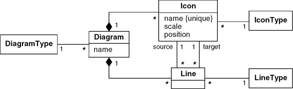
Composition is a form of aggregation with two additional constraints. A constituent part can belong to at most one assembly. Furthermore, once a constituent part has been assigned an assembly, it has a coincident lifetime with the assembly. In Figure A1.9 Icons and Lines belong to a Diagram. If a Diagram is deleted, all of its Icons and Lines are also deleted.
Generalization
Generalization is the relationship between an entity type (the supertype) and one or more variations of the entity type (the subtypes). Generalization organizes entity types by their similarities and differences, structuring the description of entities. The supertype holds common attributes and relationships; the subtypes add specific attributes and relationships. Each subtype inherits the attributes and relationships of its supertype. A hollow triangle denotes generalization. The apex of the triangle connects to the supertype. Lines connect the base of the triangle to the subtypes.
Figure A1.10 has two generalizations. One generalization has a supertype of Actor and subtypes of TangibleActor, ActorRole, and ActorRoleType. The other generalization has a supertype of TangibleActor and subtypes of Person, Application, and Organization.

Bibliographic Notes
[Chen-1976] is the classic reference for entity-relationship modeling. The other references give further information on the UML class modeling notation as well as other UML notations. The explanation of the UML class model here is abridged and only covers the constructs used in this book.
References
[Blaha-200l] Michael Blaha. A Manager's Guide to Database Technology. Upper Saddle River, New Jersey: Prentice-Hall, 2001.
[Blaha-2005] Michael Blaha and James Rumbaugh. Object-Oriented Modeling and Design with UML, 2nd Edition. Upper Saddle River, NJ: Prentice Hall, 2005.
[Chen-1976] PPS Chen. The entity-relationship model—toward a unified view of data. ACM Transactions on Database Systems 1, 1 (March 1976).
[Hoberman-2010] Steve Hoberman. Data Modeling Made Simple: A Practical Guide for Business and IT Professionals, 2nd Edition. Bradley Beach, New Jersey: Technics Publications, 2010.
[Rumbaugh-2005] James Rumbaugh, Ivar Jacobson, and Grady Booch. The Unified Modeling Language Reference Manual, Second Edition. Boston, MA: Addison-Wesley, 2005.