
Chapter 10
Kitchen Lamp
WHAT’S IN THIS CHAPTER?
- Using extremely long LED strips
- Using high-current power supplies
- Sending notifications to accessories
- Housing your boards
- Bit-banging versus SPI
In this chapter you build a kitchen lamp as an accessory to your Android device. It will be augmenting notifications from your phone (call or SMS arrivals, or the status of a timer) by means of using the light coming from a stripe with 144 full-color LEDs.
This chapter takes you through the process of building a real-life accessory, one that people use every day. We opted for a kitchen lamp, because the kitchen is an environment where it makes a lot of sense to have some sort of hands-free interaction with some of the existing appliances. We also chose a lamp because kitchens are noisy and light seems the most effective way to get feedback from the phone/tablet. We could as well connect the phone’s audio jack to a sound amplifier to listen to any kind of notifications. However, in this case you are going to explore the possibilities offered by light, its intensity and color.
We are positive you have at least one lamp in your kitchen. We hope that looking at how we brought this project to life will trigger your imagination and push you into building something that you will use. You learn the most when you try to fit the device’s behavior to your personal needs.
THE CONCEPT
We did some research looking for possible materials, and we came to the conclusion that it would be interesting to use an RGB (as in full-color) addressable LED strip, because it would enable us to make small animations to trigger different events that happen while in the kitchen. The Android device doesn’t detect whether there is anyone in the kitchen, neither does the Arduino board used in this project. It will trigger events happening in the phone/tablet like the arrival of an SMS or reaching the timeout of a timer, but if the user is not there to see them, it will be as if they hadn’t happened.
Kitchens are noisy. The air extractor might be running, or the microwave might be on, or you might be using the blender; you might be listening to louder-than-necessary music just for those reasons. How can you then notice the arrival of a certain notification on your phone? This is when the idea crossed our minds: we had to connect the RGB-LED kitchen lamp to our Android device. In that way, the phone/tablet would be triggering the events and reporting back to the LEDs.
Because this was going to be part of a real kitchen (see Figure 10-1), and a serious investment in terms of time and money had to be made, we had to put a lot of focus on creating a really high finish of the lamp. The lamp had to be aesthetically pleasant. This should not be a prototype, but a real lamp to be installed in my kitchen for the next 15 or 20 years. The lamp itself consists of a line of 114 RGB LEDs and is almost 3 m long. It is covered by a 5 mm-thick layer of translucent acrylic. The tiles on the wall are of a white that nicely matches the color of the plastic.
FIGURE 10-1: View of the kitchen mentioned in the project

Making this project required us to think in a slightly different way in comparison to the other projects included in this book. Here the object was (and is) going to be part of the everyday life of everyday people. This is a design challenge, but also an interesting opportunity and a great excuse to get hands-on with electronics and software.
THE DESIGN BRIEF
When building a project like this lamp, where we involved a furniture designer and carpenter in the process, it is convenient to have a framework that allows everyone to be on the same page. It’s not only important to budget time, but also to make sure that those building the actual objects are aware of not just the function but also the aesthetic you expect of your installation. My co-author and I were the ones deciding what materials (LEDs and power supply in this case) we were going to use. But it had to be the carpenter who figured out how to embed that into the kitchen. A 3 m-long lamp is not something you can easily get rid of.
The brief to the project allows building a framework for the different stakeholders to discuss. The following list outlines the goals of this project:
- Create a lamp to illuminate the stove and sink area of a kitchen.
- Make sure the lamp operates as a lamp (using white light) by default, requiring no further interaction from a user than pressing the on/off switch.
- Make the lamp act as an Android accessory offering the possibility of augmenting parts of the notification system of the phone by means of using light.
- Make the lamp respond to the arrival of SMS and phone calls with different light animations.
- Enable the lamp to be used as a cooking timer showing the amount of time left as a VU-meter (all the lights on is 100 percent of the time, half the lights is 50 percent of the time, and so on). Figure 10-2 is an example of this functionality.
FIGURE 10-2: Lamp acting as VU-meter

THE ARDUINO SIDE
This project’s bill of materials does not include many parts (see Figure 10-3). Essentially, you need the Arduino Mega ADK, some small parts, and an LED strip. The key to having a lamp you really want to use and that will make your kitchen time more enjoyable (and even playful) is choosing the right LED strip. You need to find one that is easy to control from your software with a minimal set of commands.
FIGURE 10-3: Parts needed in the kitchen lamp project

Many types of LED strips are available, and they differ depending on which drivers they use to control the LEDs. The drivers are chips that can control both the amount and color of light projected by each LED, and the communication to/from the microcontroller board.
The LED lamp, which we had designed for the kitchen, had to be placed on top of the area where we cook. The furniture designer suggested making a lamp as long as the kitchen’s bench. A nice way of making a lamp that long (3 meters in this case) is using LED strips.
What allows having very long LED strips is the fact that those drivers can be daisy-chained. They have a serial-in pin and a serial-out pin. The data comes in through the input and, one instant later, it is pushed out through the output. Yet another pin on the chip, called a latch, tells the chips whether they should load the data in their internal memory, thus pushing different RGB values to the LEDs, or if they (the chips) should just do nothing about that data.
This brings a certain complexity in the software. If you want to change the color of a certain LED, you will need to send data for all the LEDs at once. You can do this via software by keeping a buffer in memory to store the color information for all the LEDs and pushing out the whole buffer toward the strip every time you want to change the color of one or many of the LEDs.
But you are lucky this time! Because this type of strip has been around for quite a while, you can find a whole series of different libraries to gracefully handle the strip. You just need to find the one that best accommodates your needs.
- Adafruit’s library (you will need to make a small modification to make it compatible with Arduino 1.0.1 or later; the library in the downloads section on the website of this book is based on this one and fixes any issues. However, we added this library here for reference): https://github.com/adafruit/HL1606-LED-Strip
- Synoptic Labs’ library: http://code.google.com/p/ledstrip/
- The fastSPI library: http://code.google.com/p/fastspi/
Hardware
If, like in this project, you are going to deploy a prototype in a real setting, you have to consider things like the box you’ll use to host the device and a power supply that can provide enough current to run everything. LEDs are very power-hungry; in particular, the 114 RGB ones running this lamp have empirically been shown to need 2.3 Amps as measured at our laboratory.
The final list of parts for this project is as follows:
- Arduino Mega ADK + micro USB cable for your processor.
- Arduino prototyping shield for Arduino Mega.
- Pin headers, both male-only and female, with long pins.
- Pushbuttons (these are optional, but they are handy for troubleshooting your installation when you do not have a computer).
- Multithreaded wire. Because it will be carrying a significant amount of current, you should use multithreaded wire for power and ground.
- H-U Terminal Block connectors to join the wires.
- Switched 5 V power supply. We used one with metallic housing to make sure it would be safe to use in a demanding environment like the kitchen. You cannot put a power supply providing 3 or 4 Amps in a tiny wooden box. You can hide your power supply in a locker, but make sure there is enough air in the box for the supply to cool down (a kitchen locker sized 35 × 40 × 60 cms will be enough). Ours is capable of providing 8 Amps, even though this project needs a maximum of only 2.3 Amps.
- An LED strip. We used one with HL1606 drivers, but many different ones are available. Just find one with good documentation so that you can write a basic communication library if one doesn’t already exist. The strip we used is shielded in a transparent silicon case, which makes it suitable for the kitchen environment because the electronics are protected from steam and possibly food that could short-circuit any of the wires.
- A plastic box for the Arduino + Shield combo as they don’t heat up at all. We used the standard plastic box for Arduino projects provided by the Arduino store, but anything will suffice.
The schematic for the shield is shown in Figure 10-4. It shows that we have connected a male pin header on the shield for providing the data, clock, and latch signals to the strip. We have also added a bunch of buttons to test that the different light patterns work in the project.
FIGURE 10-4: Project schematic

The power for the whole system comes from the 5 V power supply. We simply added a wire to the 5 V pin on the shield (and another to the GND pin) to draw power from the same supply feeding the LED strip.
In our case, the strip came with a connector exposing the different pins. It might be different for you. In that case, you should solder wires from the different anchor points in the strip. As mentioned earlier, the LED driver we are using is called HL1606 and it exposes the following pins (in order):
- GND — Ground or 0 Volts.
- SI/SO — Strobe. This is not used in the code, but we chose to wire it up anyway for future development. The strobe at SI is transferred directly to SO on the chip.
- DI/DO — Data pin carrying the information bit by bit. The current bit is passed out to DO at the arrival of the next clock edge.
- CI/CO — Clock. At the arrival of a rising edge on the clock signal, the HL1606 loads the voltage value on the DI pin into memory.
- LI/LO — Latch. Tells the driver to load the values inside memory onto the LEDs.
- 5 V — Power to the strip, it has to be exactly 5 Volts and will need enough current to make all the LEDs shine. In our case, 114 LEDs need 2.3 Amps of current at 5 Volts.
Figure 10-5 shows one segment of the LED strip with two LEDs and the driver chip in between. On the left side you can see the inputs to the segment, and on the right side you see the outputs. This particular strip comes as a series of these segments tied up to each other. Some of them will be casted in silicon (like the one we are showing), but some of them won’t.
FIGURE 10-5: Segment of the strip

It is possible to solder wires directly on the metallic contacts at the input of the strip segment and connect it directly to a microcontroller. It is also possible to feed the 5 V needed for the strip directly from the 5 V output coming from your Arduino, as long as you do not have many LEDs hanging from that pin. The 114 LEDs used in this project are far too many, so we needed the external power supply.
As Figure 10-6 shows, we soldered everything together onto a prototyping shield, making it very easy to push the project into a box and embed the whole thing into the kitchen.
FIGURE 10-6: View of the shield on top of Arduino once soldered

Software
You are already familiar with creating basic Arduino programs, so we will jump over the very basic steps. Just keep in mind that you want to write a program that:
- Checks whether or not an Android device is connected
- Provides a constant white light if no Android device is connected
- Subscribes to the information feed and listens to data published by the Android device if connected
- Discriminates between three types of events: calls, SMS arrival, and kitchen timer
- Renders different light animations depending on the event
Create the Program’s Skeleton
The program’s skeleton contains different blocks that you have to check periodically, as well as some room for adding different light effects by means of writing your own functions on top of the HL1606 library (remember it is the driver used to control each pair of LEDs).
Listing 10-1 shows an idea of the whole program you need to produce. Note that this is pseudo code and not real code!
LISTING 10-1: Program’s skeleton
#include <libraries_LEDs>
#include <libraries_Communication>
int declareSomeVariables;
libLEds strip = stripConstructor();
libComm mqtt = mqttConstructor();
void setup() {
  initSerialComm(); // to debug that things are going ok
  mqtt.initMqttComm(); // to establish the communication towards the Android device
}
void loop() {
  if(!connected) strip.turnOnWhiteLight();
  if(connected && !subscribed) subscribed = mqtt.subscribe();
  if(subscribed) {
    if(mqtt.publishArrived()) executeCommand(mqtt.getPayload());
  }
}
void executeCommand(int com) {
  switch (com) {
    case CALL:
      lightAnimationCall();
      break;
    case SMS:
      lightAnimationSMS();
      break;
    case TIMER:
      barGraph(mqtt.getPayload()[1]); // check the second byte
      break;
  }
}
[... here you should add the different animations to be performed on the LEDs ...]
Add the Libraries to Control the LEDs
If you understand the basic skeleton for the program, it then becomes fairly easy to translate it into real code. You just need to go step by step. As for the LEDs, we used the HL1606 library. It is not the latest code, but it is properly documented because a whole lot of people have been using it.
- HL1606strip (data, latch, clock, LEDs) — This is the constructor. You have to specify the pins you used to connect the data, latch, clock, and the total amount of LEDs in the strip.
- HL1606strip::setLEDcolor(i, color) — This function changes the color of one of the LEDs on the strip, but only on the buffer. The change is not executed until you call HL1606::writeStrip().
- HL1606::writeStrip() — This function sends the buffer containing the light data down to the whole strip.
- There are a series of predefined colors for you to choose, the library defines them as constants: BLACK, WHITE, TEAL, BLUE, RED, GREEN, YELLOW and VIOLET.
Using the library’s basic function set and color definitions, we created the functions doubleDipping(), vuMeter(), and knightRider() to inform about the arrival of different notifications. These functions are introduced in Listing 10-2.
LISTING 10-2: Libraries, constructors, and functions for the strip
#include <HL1606strip.h>

#define STRIP_D 36
#define STRIP_C 38
#define STRIP_L 40
#define NUM_LEDS 114

HL1606strip strip = HL1606strip(STRIP_D, STRIP_L, STRIP_C, NUM_LEDS);

void setup() {
}
void loop() {
  // cycle trough the different examples
  knightRider(5);
  doubleDipping(WHITE);
  for(int i = 0; i < 100; i++) {
    vuMeter(i);
    delay(100);
  }
}

// the parameter fixes the amount of LEDs that
// will be moving back and forth
void knightRider(int width) {
  for (int i=0; i< strip.numLEDs() - width; i++) {
    for (int j = 0; j < width; j++)
      strip.setLEDcolor(i+j, RED);
    if (i != 0)
      strip.setLEDcolor(i-1, BLACK);
    strip.writeStrip();
  }
  for (int i=strip.numLEDs() - width; i > 0; i--) {
    for (int j = 0; j < width; j++)
      strip.setLEDcolor(i+j, RED);
    if (i != 0)
      strip.setLEDcolor(i+width, BLACK);
    strip.writeStrip();
  }
}

// doubleDipping takes the color we will use to light up
// the LEDs
void doubleDipping(int color) {
  for (int i=0; i< int(strip.numLEDs()/2); i++) {
    strip.setLEDcolor(i, color);
    strip.setLEDcolor(strip.numLEDs() - i, color);
    strip.writeStrip();
  }
}

// the parameter determines in percentage how many
// LEDs will be on
void vuMeter(int percent) {
  for (int i=0; i< int(strip.numLEDs()*percent/100); i++) {
    strip.setLEDcolor(i, BLUE);
  }
  for (int i=int(strip.numLEDs()*percent/100); i < strip.numLEDs(); i++) {
    strip.setLEDcolor(i, BLACK);
  }
  strip.writeStrip();
}
Add the Libraries to Control Communication
Next you add the code to control the communication from the phone. Note that we named the initialization method after the application running on the phone/tablet.
To make the code a little easier to read, in Listing 10-3 we separated the execution of the different animations into a different function called executeCommand().
LISTING 10-3: Communication libraries and payload analysis
#include <AndroidAccessory.h>
#include <P2PMQTT.h>
#include <HL1606strip.h>

#define STRIP_D 36
#define STRIP_C 38
#define STRIP_L 40
#define NUM_LEDS 114

#define VUMETER 0
#define SMS 1
#define CALL 2

HL1606strip strip = HL1606strip(STRIP_D, STRIP_L, STRIP_C, NUM_LEDS);

P2PMQTT mqtt(true);  // add true to see debug info over the serial port
boolean subscribed = false;

void setup() {
  Serial.begin(9600);
  Serial.println("ready");
  mqtt.begin("Kitchen Lamp");
}
void loop() {
  int firstByteMSB = mqtt.getType(mqtt.buffer);
  int payload = 0;

  switch(firstByteMSB) {
    case CONNECT:
      Serial.println("connected");
      if(!subscribed) subscribed = mqtt.subscribe("kl");
      break;

    case PUBLISH:
      payload = mqtt.getPayload(mqtt.buffer,PUBLISH)[0];
      executeCommand(payload);
      break;

    default:
      // do nothing
      break;
  }
}
void executeCommand(int c) {
  int val = 0;
  switch (c) {
    case VUMETER:
      // VU meter sends the value in the second byte
      // of the payload
      val = mqtt.getPayload(mqtt.buffer,PUBLISH)[1];
      vuMeter(val);
      break;

    case SMS:
      doubleDipping(WHITE);
      break;

    case CALL:
      knightRider(5);
      break;
    default:
      // do nothing
      break;
  }
}
[...]
Periodically Check Whether or Not the Android Device Is Connected
The final part of the code (Listing 10-4) for getting this project to work is analyzing whether there is a connection to the phone/tablet. If nothing is connected, the lamp should just be on. You will do a periodic check to make sure devices can be connected to or disconnected from the lamp at any time.
You have to add a boolean variable to monitor whether it is the first time the program’s main loop runs. If it is the case, the lamp should simply go on. There is also a timer to check from time to time if the Android device is connected.
You also need the function that turns all the LEDs on: lightsON(). It takes the color as a parameter.
LISTING 10-4: Ensuring the “lamp as such” functionality
#include <AndroidAccessory.h>
#include <P2PMQTT.h>
#include <HL1606strip.h>

[...]

boolean firstTime = true;
long timer = 0;

void setup() {
  Serial.begin(9600);
  Serial.println("ready");
  mqtt.begin("Kitchen Lamp");
}
void loop() {
  if(firstTime || (millis() - timer > 1000 && !mqtt.isConnected())) {
     lightsON(WHITE);
     timer = millis();
     firstTime = false;
  }
  int firstByteMSB = mqtt.getType(mqtt.buffer);
  int payload = 0;

  switch(firstByteMSB) {
    [...]
  }
}

// turn the all the LEDs on taking color as a parameter
void lightsON(int color) {
  for (uint8_t i=0; i < strip.numLEDs(); i++) {
    strip.setLEDcolor(i, color);
  }
  strip.writeStrip();
}
[...]
Embedded Code Done, What is Next?
You now have a lamp up and running. When plugged to the power socket, it will get lit and shine with all the LEDs at once. Next step is producing the Android app to command your lamp. The following section will guide you in creating an Android program capable of responding to events like SMS messages or calls by sending commands to the kitchen lamp.
BUILDING THE ANDROID APP
In this project your Android application acts as the P2PMQTT server, meaning it distributes all the data to the Arduino microcontroller (the accessory) and controls the current status of the lamp. You need to add at least the following three data sources to your app, but you can add more if you want:
- Act as a kitchen timer
- Catch incoming phone calls
- Catch incoming text messages
This might seem like a very large application just by viewing these sources, but remember that Android has most of these capabilities built into the very core of the system; the resulting project will be fairly simple to build.
Sketching the Application Layout
This first version of the accessory application consists of only two classes: the Activity and a class for constants. Of course, you can expand the project later on; for example, you can add an AsyncTask to get information from Yahoo! Weather and displaying it through the kitchen lamp.
Create the Kitchen Lamp Project
Start by creating the Eclipse project. In this example it’s called Kitchen Lamp and will have the package com.wiley.aoa.kitchen_lamp. These are just suggested values; you can select any names you want, but make sure to remember them throughout the chapter.
Create the User Interface
The user interface for the Kitchen Lamp application consists of a timer section and a set of checkboxes used to enable or disable event listeners. You’ll build this interface using something called a ViewFlipper, which is a container that can animate transitions between multiple views without causing the lifecycle events to be called.
Add the ViewFlipper tag as shown in Listing 10-5. This allows the user to swipe between the two different views without using multiple activities and dealing with lifecycle events; the views will then also share the same accessory connection.
LISTING 10-5: Add the ViewFlipper root
<?xml version="1.0" encoding="utf-8"?>
<LinearLayout xmlns:android="http://schemas.android.com/apk/res/android"
  android:layout_width="match_parent"
  android:layout_height="match_parent"
  android:orientation="vertical" >
  <ViewFlipper
    android:id="@+id/viewFlipper1"
    android:layout_width="match_parent"
    android:layout_height="match_parent" >
  </ViewFlipper>
</LinearLayout>
The ViewFlipper contains two views. The first allows control over the timer, and the second lets the user select what events to listen for. When you notice that a layout file may grow fairly large, it’s always a good idea to consider using the tools available to simplify the code; in this case you’ll use the include tag rather than adding the two views directly to the activity_main.xml layout.
You’ll also need some way to switch between the views in the ViewFlipper; often you’d probably want to react to a swipe gesture, but in this example you’ll use a simple Button. Add the two include tags and the button as shown in Listing 10-6.
LISTING 10-6: Add two include tags
<?xml version="1.0" encoding="utf-8"?>
<?xml version="1.0" encoding="utf-8"?>
<LinearLayout xmlns:android="http://schemas.android.com/apk/res/android"
  android:layout_width="match_parent"
  android:layout_height="match_parent"
  android:orientation="vertical" >
  <ViewFlipper
    android:id="@+id/viewFlipper1"
    android:layout_width="match_parent"
    android:layout_height="wrap_content" >
    <include
      android:layout_width="match_parent"
      android:layout_height="match_parent"
      layout="@layout/timer_view" />
    <include
      android:layout_width="match_parent"
      android:layout_height="match_parent"
      layout="@layout/event_view" />
  </ViewFlipper>
  <Button
    android:id="@+id/button1"
    android:layout_width="wrap_content"
    android:layout_height="wrap_content"
    android:layout_gravity="center_horizontal"
    android:text="Switch View"
    android:onClick="switchView" />
</LinearLayout>
Before you continue on to building the rest of the user interface make sure to add the switchView method to your MainActivity, as shown in Listing 10-7.
LISTING 10-7: Add the switchView method
package com.wiley.aoa.kitchen_lamp;
import android.app.Activity;
import android.os.Bundle;
import android.view.View;
import android.widget.ViewFlipper;
public class MainActivity extends Activity {
  private ViewFlipper mViewFlipper;
  @Override
  public void onCreate(Bundle savedInstanceState) {
    super.onCreate(savedInstanceState);
    setContentView(R.layout.activity_main);
    mViewFlipper = (ViewFlipper) findViewById(R.id.viewFlipper1);
  }
  public void switchView(View v){
    mViewFlipper.showNext();
  }
}
Include tags allow Android to copy and paste the layout files together to form one complete file. For you this means that you can treat each view separately when coding, and it also means that you can see both views in the Layout Editor if you prefer to work in the WYSIWYG mode. Create the two new layout files, timer_view.xml and event_view.xml:
To create the event_view layout repeat the above steps, but entering event_view instead to create the second view for the ViewFlipper.
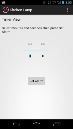
The timer_view allows the user to set alarms, which when fired make the kitchen lamp light up in a certain pattern.
Give the view a title that tells the user what it does (remember the Android Design Guidelines and keep all text brief). The time for the alarm will be set using something called a NumberPicker, which is available in the Advanced drawer of the Layout Editor palette. To actually set the alarm you’ll use a Button, place the button under the NumberPickers.
Add the TextView, the two NumberPicker elements and the Button to your timer_view layout, as shown in Listing 10-8.
LISTING 10-8: Build the timer_view layout
<?xml version="1.0" encoding="utf-8"?>
<LinearLayout xmlns:android="http://schemas.android.com/apk/res/android"
  android:layout_width="match_parent"
  android:layout_height="match_parent"
  android:orientation="vertical" >
  <TextView
    android:id="@+id/timer_title"
    android:layout_width="match_parent"
    android:layout_height="wrap_content"
    android:layout_margin="10dp"
    android:text="Timer View"
    android:textAppearance="?android:attr/textAppearanceLarge" />
  <TextView
    android:id="@+id/timer_text"
    android:layout_width="wrap_content"
    android:layout_height="wrap_content"
    android:layout_margin="10dp"
    android:text="Select minutes and seconds, then press Set Alarm."
    android:textAppearance="?android:attr/textAppearanceMedium" />
  <LinearLayout
    android:layout_width="wrap_content"
    android:layout_height="wrap_content"
    android:layout_gravity="center_horizontal"
    android:layout_margin="10dp" >
    <NumberPicker
      android:id="@+id/picker_minutes"
      android:layout_width="wrap_content"
      android:layout_height="wrap_content" />
    <NumberPicker
      android:id="@+id/picker_seconds"
      android:layout_width="wrap_content"
      android:layout_height="wrap_content" />
  </LinearLayout>
  <Button
    android:id="@+id/button_timer"
    android:layout_width="wrap_content"
    android:layout_height="wrap_content"
    android:layout_gravity="center_horizontal"
    android:text="Set Alarm"
    android:onClick="setAlarm" />
</LinearLayout>
The finished timer_view should look something like Figure 10-7.
FIGURE 10-7: The finished timer_view layout
Notice the onClick attribute set in the button; if you prefer, you can use an OnClickListener within your activity instead. However, using the onClick attribute produces less code in the activities, which is a good thing. Go ahead and add the setAlarm method to your MainActivity directly so that you avoid any unnecessary exceptions later. See Listing 10-9.
LISTING 10-9: Add the setAlarm method
package com.wiley.aoa.kitchen_lamp;
import android.app.Activity;
import android.os.Bundle;
import android.view.View;
public class MainActivity extends Activity {
  @Override
  protected void onCreate(Bundle savedInstanceState) {
    super.onCreate(savedInstanceState);
    setContentView(R.layout.activity_accessory);
  }
  public void setAlarm(View v) {
  }
}
The event_view contains three checkboxes, letting the user select what events to listen for. These just register and unregister the broadcast receiver for each event. Add the code in Listing 10-10 to your event_view.xml.
LISTING 10-10: Build the event_view layout
<?xml version="1.0" encoding="utf-8"?>
<LinearLayout xmlns:android="http://schemas.android.com/apk/res/android"
  android:layout_width="match_parent"
  android:layout_height="match_parent"
  android:orientation="vertical" >
  <TextView
    android:id="@+id/event_title"
    android:layout_width="wrap_content"
    android:layout_height="wrap_content"
    android:layout_margin="10dp"
    android:text="Event View"
    android:textAppearance="?android:attr/textAppearanceLarge" />
  <TextView
    android:id="@+id/event_text"
    android:layout_width="wrap_content"
    android:layout_height="wrap_content"
    android:layout_margin="10dp"
    android:text="Listen for the following events:"
    android:textAppearance="?android:attr/textAppearanceMedium" />
  <CheckBox
    android:id="@+id/check_sms"
    android:layout_width="wrap_content"
    android:layout_height="wrap_content"
    android:layout_margin="10dp"
    android:text="SMS messages" />
  <CheckBox
    android:id="@+id/check_phone"
    android:layout_width="wrap_content"
    android:layout_height="wrap_content"
    android:layout_margin="10dp"
    android:text="phone calls" />
  <CheckBox
    android:id="@+id/check_weather"
    android:layout_width="wrap_content"
    android:layout_height="wrap_content"
    android:layout_margin="10dp"
    android:text="weather updates" />
</LinearLayout>
The event_view user interface should look something like Figure 10-8.
FIGURE 10-8: The finished event_view UI

Building the Kitchen Timer
To build the kitchen timer functionality you use a class called CountDownTimer; this class lets you create an event sometime in the future by entering a number of milliseconds. It then counts down to 0 from that specific time at an interval which you define.
Before you create the CountDownTimer, you should store the references to the UI that will control the time in the future. Add the references to the NumberPickers and then set their respective maximum values, as shown in Listing 10-11.
LISTING 10-11: Add references to the NumberPickers
package com.wiley.aoa.kitchen_lamp;
[...]
import android.widget.NumberPicker;
public class MainActivity extends Activity {
  private ViewFlipper mViewFlipper;
  private Animation next_in, next_out, previous_in, previous_out;
  private NumberPicker minutes, seconds;
  @Override
  protected void onCreate(Bundle savedInstanceState) {
    super.onCreate(savedInstanceState);
    setContentView(R.layout.activity_accessory);
    mGestureDetector = new GestureDetector(this, mGestureListener);
    mViewFlipper = (ViewFlipper) findViewById(R.id.viewFlipper1);
    next_in = AnimationUtils.loadAnimation(this, R.anim.transition_next_in);
    next_out = AnimationUtils.loadAnimation(this, R.anim.transition_next_out);
    previous_in = AnimationUtils.loadAnimation(this, R.anim.transition_previous_in);
    previous_out = AnimationUtils.loadAnimation(this, R.anim.transition_previous_out);
    minutes = (NumberPicker) findViewById(R.id.picker_minutes);
    minutes.setMaxValue(60);
    seconds = (NumberPicker) findViewById(R.id.picker_seconds);
    seconds.setMaxValue(60);
  }
  [...]
}
Add the CountDownTimer instance to your MainActivity, and let the method setAlarm read how far into the future the alarm is set. See Listing 10-12 for details.
LISTING 10-12: Add the CountDownTimer
package com.wiley.aoa.kitchen_lamp;
import java.util.concurrent.TimeUnit;
[...]
public class MainActivity extends Activity {
  [...]
  private CountDownTimer timer;
  [...]
  public void setAlarm(View v) {
    if (timer != null)
      timer.cancel();
    long min = minutes.getValue() + TimeUnit.SECONDS.toMillis(seconds.getValue()
    long millisInFuture = TimeUnit.MINUTES.toMillis(min);
    timer = new CountDownTimer(millisInFuture, Constants.TIMER_COUNTDOWN) {
      @Override
      public void onTick(long millisUntilFinished) {
      }
      @Override
      public void onFinish() {
      }
    }.start();
  }
  [...]
}
You’ll notice that there’s another constant called TIMER_COUNTDOWN; add it to the Constants class with a value of 250 milliseconds. See Listing 10-13 for details. You can change the value of this constant to something that feels alright for you; remember, though, that these updates will be sent to the accessory as well, so don’t update too often!
LISTING 10-13: Add the TIMER_COUNTDOWN constant
package com.wiley.aoa.kitchen_lamp;
public class Constants {
  public static final int MIN_SWIPE_LENGTH = 100;
  public static final int TIMER_COUNTDOWN = 250;
}
When the timer updates it’s always a good idea to give some sort of feedback to the user. In this project you update the Kitchen Lamp itself, but you should also update the user interface on the application. Add the updateTime method in your activities as shown in Listing 10-14.
LISTING 10-14: Let the CountDownTimer update the NumberPickers
[...]
public class MainActivity extends Activity {
  [...]
  public void setAlarm(View v) {
    if (timer != null)
      timer.cancel();
    long millisInFuture = TimeUnit.HOURS.toMillis(hours.getValue())
        + TimeUnit.MINUTES.toMillis(minutes.getValue())
        + TimeUnit.SECONDS.toMillis(seconds.getValue());
    timer = new CountDownTimer(millisInFuture, Constants.TIMER_COUNTDOWN) {
      @Override
      public void onTick(long millisUntilFinished) {
        updateTime(millisUntilFinished);
      }
      @Override
      public void onFinish() {
        updateTime(0);
      }
    }.start();
  }
  [...]
  private void updateTime(long millis){
    int m = (int) TimeUnit.MILLISECONDS.toMillis(millis);
    minutes.setValue(m);
    int s = (int) TimeUnit.MILLISECONDS.toMillis(millis);
    seconds.setValue(s);
  }
}
Responding to Phone Calls
Android has a large number of various system-generated events; some of these events are related to the phone. You’ll tap into this functionality in your Kitchen Lamp application to send notifications to the accessory when the phone is ringing.
Start by creating the BroadcastReceiver used to detect phone calls. Add the code from Listing 10-15 to your MainActivity.
LISTING 10-15: The BroadcastReceiver for the phone state events
import android.content.BroadcastReceiver;
[...]
public class MainActivity extends Activity {
  [...]
  private BroadcastReceiver phoneReceiver = new BroadcastReceiver() {
    @Override
    public void onReceive(Context context, Intent intent) {
    }
  };
}
The broadcast ACTION_PHONE_STATE is sent whenever the state of the phone changes. This isn’t limited to when the phone is ringing, so you need to add extra filtering methods in your receiver. See Listing 10-16 for details.
LISTING 10-16: Listen only to the phone state RINGING
[...]
private BroadcastReceiver phoneReceiver = new BroadcastReceiver() {
  @Override
  public void onReceive(Context context, Intent intent) {
    String state = intent.getExtras().getString(TelephonyManager.EXTRA_STATE);
    if (state.equals(TelephonyManager.EXTRA_STATE_RINGING)) {
    }
  }
};
[...]
To register this receiver you need an IntentFilter, and because you want to be able to register and unregister throughout the lifetime of the application you should create a method that handles these actions for you. See Listing 10-17.
LISTING 10-17: Create the method to register and unregister the phoneReceiver
import android.content.IntentFilter;
import android.telephony.TelephonyManager;
[...]
public class MainActivity extends Activity {
  private IntentFilter phoneFilter;
  [...]
  private void registerPhone(boolean register) {
    if (phoneFilter == null) {
      phoneFilter = new IntentFilter();
      phoneFilter.addAction(TelephonyManager.ACTION_PHONE_STATE_CHANGED);
    }
    if (register) {
      registerReceiver(phoneReceiver, phoneFilter);
    } else {
      unregisterReceiver(phoneReceiver);
    }
  }
  private BroadcastReceiver phoneReceiver = new BroadcastReceiver() {
    @Override
    public void onReceive(Context context, Intent intent) {
    }
  };
}
With the receiver set and the registration method created, all you need to do is call the registerPhone method and pass the correct state to toggle the listener on or off. You toggle the state from an OnCheckedChangeListener (see Listing 10-18).
Notice that there’s another boolean variable introduced in this listing called phoneRegistered; this is only to track the changes in the listeners and, if a certain listener is registered by the time the application hits the onDestroy method, that receiver has to be unregistered.
LISTING 10-18: Add the OnCheckedChangedListener
[...]
import android.widget.CompoundButton;
import android.widget.CompoundButton.OnCheckedChangeListener;
public class MainActivity extends Activity {
  private CheckBox chkPhone;
  private IntentFilter phoneFilter;
  private boolean phoneRegistered;
  @Override
  public void onCreate(Bundle savedInstanceState) {
    super.onCreate(savedInstanceState);
    setContentView(R.layout.activity_accessory);
    [...]
    chkPhone = (CheckBox) findViewById(R.id.check_phone);
    chkPhone.setOnCheckedChangeListener(checkboxListener);
  }
  @Override
  protected void onDestroy() {
    super.onDestroy();
    if (phoneRegistered)
      registerPhone(false);
  }
  [...]
  private void registerPhone(boolean register) {
    if (phoneFilter == null) {
      phoneFilter = new IntentFilter();
      phoneFilter.addAction(TelephonyManager.ACTION_PHONE_STATE_CHANGED);
    }
    if (register)
      registerReceiver(phoneReceiver, phoneFilter);
    else
      unregisterReceiver(phoneReceiver);
  }
  private BroadcastReceiver phoneReceiver = new BroadcastReceiver() {
    @Override
    public void onReceive(Context context, Intent intent) {
      String state = intent.getExtras().getString(TelephonyManager.EXTRA_STATE);
      if (state.equals(TelephonyManager.EXTRA_STATE_RINGING)) {
      }
    }
  };
  private OnCheckedChangeListener checkboxListener = new OnCheckedChangeListener() {
    @Override
    public void onCheckedChanged(CompoundButton buttonView,
        boolean isChecked) {
      if (buttonView.getId() == R.id.check_phone) {
        registerPhone((phoneRegistered = isChecked));
      }
    }
  };
}
Your app is now ready to receive phone state broadcasts when the user selects the correct checkbox from the UI. One thing is missing, though. As is common on Android, many actions and services require a specific permission; this is a safety measure that allows the user to see clearly what parts of the device your application have access to. Listening to the phone state broadcasts is one of those things. Add the <uses-permission> tag to the AndroidManifest.xml, as shown in Listing 10-19.
LISTING 10-19: Ask for permission to listen to phone state events
<manifest xmlns:android="http://schemas.android.com/apk/res/android"
    package="com.wiley.aoa.kitchen_lamp"
    android:versionCode="1"
    android:versionName="1.0" >
    <uses-sdk
        android:minSdkVersion="12"
        android:targetSdkVersion="15" />
    <uses-permission android:name="android.permission.READ_PHONE_STATE" />
    <application
        android:icon="@drawable/ic_launcher"
        android:label="@string/app_name"
        android:theme="@style/AppTheme" >
        <activity
            android:name=".MainActivity"
            android:label="@string/title_activity_main" >
            <intent-filter>
                <action android:name="android.intent.action.MAIN" />
                <category android:name="android.intent.category.LAUNCHER" />
            </intent-filter>
        </activity>
    </application>
</manifest>
Listen for SMS Events
SMS events, just like the phone state events, are broadcast by the system openly so that any application that wants to listen for new SMS messages can. However, there is one catch. There is no constant defined in the TelephoneManager class for the SMS_MESSAGE event. You’ll have to either type the correct string in or create another constant in the Constants class. The latter is recommended because it makes the code a little bit more readable. Add the SMS_RECEIVED constant as shown in Listing 10-20.
LISTING 10-20: Add the SMS_RECEIVED constant
package com.wiley.aoa.kitchen_lamp;
public class Constants {
  public static final int MIN_SWIPE_LENGTH = 100;
  public static final int TIMER_COUNTDOWN = 250;
  static final String SMS_RECEIVED = "android.provider.Telephony.SMS_RECEIVED";
}
Add another broadcast receiver to your MainActivity.java; this receiver listens specifically for SMS_RECEIVED events, which are sent only when a new SMS has been received. You don’t have to add any extra filtering inside the receiver. See Listing 10-21 for details.
LISTING 10-21: The SMS_RECEIVED listener
public class MainActivity extends Activity {
  [...]
  private BroadcastReceiver smsReceiver = new BroadcastReceiver() {
    @Override
    public void onReceive(Context context, Intent intent) {
    }
  };
}
Add the registerSms method, which is almost identical to the registerPhone() method. Listing 10-22 highlights the differences.
LISTING 10-22: Create the registerSms method
import android.content.IntentFilter;
import android.telephony.TelephonyManager;
[...]
public class MainActivity extends Activity {
  private IntentFilter phoneFilter, smsFilter;
  [...]
  private void registerSms(boolean register) {
    if (smsFilter == null) {
      smsFilter = new IntentFilter();
      smsFilter.addAction(Constants.SMS_RECEIVED);
    }
    if (register)
      registerReceiver(smsReceiver, smsFilter);
    else
      unregisterReceiver(smsReceiver);
  }
  private BroadcastReceiver smsReceiver = new BroadcastReceiver() {
    @Override
    public void onReceive(Context context, Intent intent) {
    }
  };
}
Call the registerSms method from the OnCheckedChangeListener, as shown in Listing 10-23.
LISTING 10-23: Call the registerSms method
[...]
public class MainActivity extends Activity {
  [...]
  private CheckBox chkPhone, chkSms;
  private IntentFilter phoneFilter, smsFilter;
  private boolean phoneRegistered, smsRegistered;
  @Override
  public void onCreate(Bundle savedInstanceState) {
    super.onCreate(savedInstanceState);
    setContentView(R.layout.activity_main);
    [...]
    chkPhone = (CheckBox) findViewById(R.id.check_phone);
    chkPhone.setOnCheckedChangeListener(checkboxListener);
    chkSms = (CheckBox) findViewById(R.id.check_sms);
    chkSms.setOnCheckedChangeListener(checkboxListener);
  }
  @Override
  protected void onDestroy() {
    super.onDestroy();
    if (phoneRegistered)
      registerPhone(false);
    if (smsRegistered)
      registerSms(false);
  }
  [...]
  private OnCheckedChangeListener checkboxListener = new OnCheckedChangeListener() {

    @Override
    public void onCheckedChanged(CompoundButton buttonView, boolean isChecked) {
      if (buttonView.getId() == R.id.check_phone) {
        registerPhone((phoneRegistered = isChecked));
      } else if (buttonView.getId() == R.id.check_sms) {
        registerSms((smsRegistered = isChecked));
      }
    }
  };
  private void registerPhone(boolean register) {
    if (phoneFilter == null) {
      phoneFilter = new IntentFilter();
      phoneFilter.addAction(TelephonyManager.ACTION_PHONE_STATE_CHANGED);
    }
    if (register)
      registerReceiver(phoneReceiver, phoneFilter);
    else
      unregisterReceiver(phoneReceiver);
  }
  private void registerSms(boolean register) {
    if (smsFilter == null) {
      smsFilter = new IntentFilter();
      smsFilter.addAction(Constants.SMS_RECEIVED);
    }
    if (register)
      registerReceiver(smsReceiver, smsFilter);
    else
      unregisterReceiver(smsReceiver);
  }
  private BroadcastReceiver phoneReceiever = new BroadcastReceiver() {
    @Override
    public void onReceive(Context context, Intent intent) {
      String state = intent.getExtras().getString(TelephonyManager.EXTRA_STATE);
      if (state.equals(TelephonyManager.EXTRA_STATE_RINGING)) {
        // TODO
      }
    }
  };
  private BroadcastReceiver smsReceiver = new BroadcastReceiver() {
    @Override
    public void onReceive(Context context, Intent intent) {
      // TODO
    }
  };
}
Just like the phone event listener, you need to ask for permission to receive SMS events. Add the uses-permission to your AndroidManifest.xml file, as shown in Listing 10-24.
LISTING 10-24: Add the uses-permission to receive SMS events
<manifest xmlns:android="http://schemas.android.com/apk/res/android"
  package="com.wiley.aoa.kitchen_lamp"
  android:versionCode="1"
  android:versionName="1.0" >
  <uses-sdk
    android:minSdkVersion="12"
    android:targetSdkVersion="15" />
  <uses-permission android:name="android.permission.RECEIVE_SMS" />
  <uses-permission android:name="android.permission.READ_PHONE_STATE" />
  <application
    android:icon="@drawable/ic_launcher"
    android:label="@string/app_name"
    android:theme="@style/AppTheme" >
    <activity
      android:name=".MainActivity"
      android:label="@string/title_activity_main" >
      <intent-filter>
        <action android:name="android.intent.action.MAIN" />
        <category android:name="android.intent.category.LAUNCHER" />
      </intent-filter>
    </activity>
    <activity android:name="Usb12Activity" >
    </activity>
    <activity android:name="Usb10Activity" >
    </activity>
  </application>
</manifest>
Connecting to the WroxAccessory
Adding the WroxAccessories code is a simple task, thanks to your previous work in developing the WroxAccessories library. Follow these steps to add the WroxAccessories library to your project:
Having added the library as part of the build path you can now add the needed code to your MainActivity.java file. First add the needed WroxAccessory objects, as shown in Listing 10-25.
LISTING 10-25: Add the needed WroxAccessory objects
import com.wiley.wroxaccessories.UsbConnection12;
import com.wiley.wroxaccessories.WroxAccessory;
import android.hardware.usb.UsbManager;
[...]
public class MainActivity extends Activity {
  private WroxAccessory mAccessory;
  private UsbManager mUsbManager;
  private UsbConnection12 connection;
  [...]
  @Override
  public void onCreate(Bundle savedInstanceState) {
    [...]
    mUsbManager = (UsbManager) getSystemService(USB_SERVICE);
    connection = new UsbConnection12(this, mUsbManager);
    mAccessory = new WroxAccessory(this);
  }
  [...]
}
Override the onResume lifecycle method and then send the connect message to the accessory as shown in Listing 10-26.
LISTING 10-26: Perform the connect
@Override
protected void onResume() {
  super.onResume();
  try {
    mAccessory.connect(WroxAccessory.USB_ACCESSORY_12, connection);
  } catch (IOException e) {
    e.printStackTrace();
  }

}
Then, in the onDestroy lifecycle method you should disconnect the accessory, which will gracefully send a disconnect message and unregister all subscriptions. As shown in Listing 10-27.
LISTING 10-27: Disconnect in the onDestroy method
@Override
protected void onDestroy() {
  super.onDestroy();
  if (phoneRegistered)
    registerPhone(false);
  if (smsRegistered)
    registerSms(false);
  try {
    mAccessory.disconnect();
  } catch (IOException e) {
    e.printStackTrace();
  }
}
The only thing missing now is to publish the right messages to the correct topic. Start with the CountDownTimer, which publishes a message to the Kitchen Lamp topic, abbreviated to “kl” in this project, with a two-byte payload; the first byte marks what message you’re sending (timer, SMS, or phone call), and the second byte contains the percent (0–100), which is only applicable to the timer in this example, but you can expand on this project and re-use that message for other kinds of events too. See Listing 10-28 for details.
LISTING 10-28: Publish VU_EVENT message
[...]
@Override
public void onTick(long millisUntilFinished) {
  setTime(millisUntilFinished);
  float percent = ((float) millisUntilFinished / (float) timer_max) * 100;
  byte[] buffer = new byte[2];
  buffer[0] = Constants.VU_EVENT;
  buffer[1] = (byte) percent;
  try {
    mAccessory.publish("kl", buffer);
  } catch (IOException e) {
    e.printStackTrace();
  }
}
[...]
The SMS event message contains only one byte. Add the publish call to the smsReceiver as shown in Listing 10-29.
LISTING 10-29: Publish SMS_EVENT message
[...]
private BroadcastReceiver smsReceiver = new BroadcastReceiver() {
  @Override
  public void onReceive(Context context, Intent intent) {
    byte[] buffer = new byte[1];
    buffer[0] = Constants.SMS_EVENT;
    try {
      mAccessory.publish("kl", buffer);
    } catch (IOException e) {
      e.printStackTrace();
    }
  }
};
[...]
Just like the publish message for the SMS event, the phone event contains just one byte; the message type. See Listing 10-30.
LISTING 10-30: Publish PHONE_EVENT message
[...]
privateBroadcastReceiver phoneReceiver = newBroadcastReceiver(){
  @Override
  publicvoidonReceive(Contextcontext,Intentintent){
    Stringstate=intent.getExtras().getString(TelephonyManager.EXTRA_STATE);
    if(state.equals(TelephonyManager.EXTRA_STATE_RINGING)){
      byte[] buffer = new byte[1];
      buffer[0] = Constants.PHONE_EVENT;
      try{
        mAccessory.publish("kl", buffer);
      }catch(IOExceptione){
        e.printStackTrace();
      }
    }
  }
};
[...]
Finally, add the message constants to the Constants.java class, as shown in Listing 10-31.
LISTING 10-31: Add all message constants to the Constants.java
public class Constants {
  static final String SMS_RECEIVED = "android.provider.Telephony.SMS_RECEIVED";
  protected static final byte VU_EVENT = 0;
  protected static final byte SMS_EVENT = 1;
  protected static final byte PHONE_EVENT = 2;
}
FURTHER IMPROVEMENTS
The final installation is shown in action in Figure 10-9. There you see how the system responds to the arrival of a call. But what are some things that you could improve if you had the time? The following sections look at those in detail.
FIGURE 10-9: Kitchen lamp informing you of a phone call

Product-ready Embedded System
We have oversimplified the embedded code to make sure it would be easy to understand how to build the program. However, you could make a couple of improvements to make a better lamp:
- It would be interesting to make more functions with more effects that would, for example, fade the light in, instead of going directly from off to on when you turn on the lamp.
- You could also imagine adding a dimming function by using a single button that you could press continuously as a way to cycle through different dimming values.
- More importantly, once there has been a notification, for example a phone call, it would be good to have a visual reminder on the lamp of missed phone calls or received text messages. You could make one LED turn red for each call, and use yet another color to inform you about every SMS arrival. This would imply using a button to deactivate the notifications on the lamp.
Making a Better App
You can improve the Android app in few very obvious ways. First, you could change the user interface to something easier and definitely something more suitable for its purpose and context:
- Moving the accessory-specific code to a Service instead would let the user interact with the screen; closing and opening the Kitchen Lamp app as they please. However, pushing the communication to a Service isn’t as straightforward as just consuming the ACCESSORY_ATTACHED event because only activities can receive it. This would also let the timer and BroadcastRecivers run in the background so that events can be handled when the app is no longer running in the foreground.
- Making the app launch on both versions of the Accessory library would be the next step in broadening the scope of devices capable of connecting to the accessory. You could do this by introducing yet another “hidden” activity with the only task of determining how to proceed; this activity would use the static Build class, polling the SDK_INT constant and then instantly sending the user to the correct destination.
- One of the design guidelines defined by Android is that of saving user-generated data. If the user has selected to listen for an event, you should save this selection in the app’s preferences and then load it up again the next time the app is launched.
- When improving the user experience you should always consider adding animations and effects as hints of how the user is navigating you application’s interface. One of the most obvious places to use animations in Android is the ViewFlipper; it even has methods specifically for defining how views should be animated.
- The ViewFlipper is one of those things in Android where gestures really makes sense; using a GestureDetector, you can detect when the user swipes across the screen with their fingers and then change views with a smooth animation (as mentioned above). This creates a much smoother user experience.
SUMMARY
Building prototypes is one thing, but making them for other people who will use them in a real setting requires a slightly different mindset. If you are thinking about how cool it would be to have a lamp or any other electric appliance controlled by the phone, also consider whether it will make sense without the phone. The life expectancy of a kitchen lamp is far longer than the one of a phone (maybe 10 or 15 times as much).
You can probably imagine a whole series of accessories that require using a phone, like in project 1 (Chapter 9), where you used the high-speed camera on the phone to make animations. In that case, the whole construction would make no sense without the phone. On the other hand, in some cases the object needs to also work on its own without a phone.
Creating an accessory that can work with or without a phone will mark the kind of embedded software you create for the accessory. It needs to have a default mode and a connected one. Once you hook up the phone, it will start commanding the object, augmenting its features.
On Android many system events such as phone calls or text messages are broadcast to the entire system, meaning you can listen in on them and react to them in any fashion you want — for example letting a special pattern be displayed on a large wall-mounted LED lamp.
Working with broadcasts is fairly easy, the only catch is to register them and unregister them at the best times. You should think of the following when working with broadcast receivers:
- Always make sure that all BroadcastReceivers are unregistered in either onPause or onDestroy, depending on if you want to receive broadcasts while your application is paused or not.
- You can register to listen for broadcasts during run time if you wish; however, there’s no list of what broadcasts your application has registered too. In order to unregister the correct BroadcastReceivers, you’ll need to track that on your own. In this project you used two boolean variables for this purpose.
There are multiple ways of working with multi-view applications, in this project you got a little bit acquainted with the ViewFlipper, which lets you load multiple layouts within the same Activity, and then select the currently active layout. There are a few benefits of working with a ViewFlipper like this:
- You don’t need to set up and maintain the accessory connection for each individual view; they all share the same connection since they are all parts of the same Activity.
- ViewFlipper contains built-in methods for animating between different views.
There is of course some downsides to this way of working as well, the code in the single Activity can easily grow quite large. In a more modern setting you would have likely used Fragments instead, which would have made the code more readable and manageable.