
Chapter 3
Understanding Data Communication
WHAT’S IN THIS CHAPTER?
- Understanding how data communication works
- The basics of how data is structured
- The fundamentals of the MQTT messaging protocol
- Sketching the P2PMQTT protocol
DATA COMMUNICATION BASICS
Never underestimate the bandwidth of a station wagon full of tapes hurtling down the highway.
—Tanenbaum, Andrew S. (1996). Computer Networks. New Jersey: Prentice-Hall. p. 83. ISBN 0-13-349945-6.
The act of communicating requires having two or more parties exchanging, requesting, sending, and evaluating data. Those involved in the information exchange can be people or machines. Successful exchanges require the use of a predetermined mechanism on how to request data, but also on how to acknowledge the arrival of it. The definition of those mechanisms is made in an abstract way and is independent of the transmission channel. It’s what we call a protocol.
Different protocols accommodate different scenarios of use. Trying to send data over a 6.000 Km long submarine cable is not the same as using a twisted pair of copper wires between two circuits at 10 cms distance from each other.
Understanding how communication works between two electronic devices requires thinking beyond the bits and electronic components themselves. You need to consider factors like noise, whether the communication happens over wires or in a wireless way, how far the devices are from each other, or how quickly you want data to be sent to the other side.
Sometimes your envisioned application cannot be achieved because of one of the factors is too limiting, but standards exist that can help you get your project done in almost any case.
At the lowest logical level, information is encoded in packages of bits. Most of the existing communication systems use packages of 8 bits (which is the same as 1 byte) as the basic unit for information transfer. Those bytes contain the data you want to send, like the temperature measured by a sensor.
Protocols
Information is seldom sent in its raw form. It is often encapsulated in bigger packages of multiple bytes to include:
- Information about the sender
- The address to the receiver
- Some description of the configuration of the sensor
- Error correction bytes
Protocols describe the way information is encoded and encapsulated to provide optimal performance during the communication, but also the way devices take turns in the communication and how they inform the different parties involved that things did or didn’t work. In other words, protocols define the way computers talk to each other.
An easy example of a communication between two devices is shown in Figure 3-1. There you see how device #1 starts a communication with device #2, which answers back.
FIGURE 3-1: Example of communication protocol between two devices

Protocols handle about every data exchange in our lives — when sending e-mail, browsing the Internet, making a secure economic transaction at an ATM, receiving SMS, and so on. Some protocols are human-readable, some others are described in bits. MQ Telemetry Transport (MQTT), the protocol we are dealing with in this book, is not human-readable, and therefore is not that easy to read at first. However, it is very efficient for small data transactions and portable to a whole series of connected devices.
Terminology
When dealing with computer communications, you are going to find a series of keywords showing up in every document describing a protocol. Table 3-1 gives you a quick look at some basic terms and what they mean, just to get acquainted with them.
TABLE 3-1: Terminology
| TERM | MEANING |
| Data | In a broad sense, data is whatever is sent between two devices. A narrower definition makes data become the actual information, taking away any overhead bytes used in the communication. |
| Header | Part of the data package containing information about the sender, the type of package, length of the data, and/or other relevant information needed to decode the package upon arrival at the other device. |
| Payload | Because the word “data” as described earlier can have such a broad meaning, this term is used to very specifically describe the actual information. |
| Package | The whole series of bytes, including header, payload, and checksum bytes, compose the so-called information packages. |
| Acknowledgment | Positive response from a receiver when a data package is received and contains no errors. This is usually labeled ACK. The opposite message is labeled NACK (as in Negative ACK) and is sent when an error was detected in a data package and the receiver wants the package sent again. |
| PING | It is standard procedure to call PING to a method in almost every communication protocol. The idea behind it is to check whether the communication between two points is still functional. |
| MSB vs. LSB | Most Significant Byte (MSB) vs. Least Significant Byte (LSB) refers to the way the payload or any other data within a package is ordered. This is needed when information is contained in more than one byte. It shouldn’t be confused with Most/Least Significant Bit. For example, if the Java short datatype is 16 bit, this means it consists of 2 bytes (2*8bit=16bit). One of these two bytes has a larger impact on the resulting value, and is called Most Significant Byte. Commonly, the Most Significant Byte is the leftmost byte in the order, and the Least Significant Byte is the rightmost byte in the order. |
| Fixed vs. Variable packages | Some protocols have packages with fixed sizes, thus the same amount of bytes for each package. MQTT has variable package sizes. This makes it harder to encode/decode, but much more efficient in bandwidth. |
| CRC | Cyclic Redundancy Check, a technique that helps detect errors happening during the transmission of a data package by making a simple mathematical operation on the data upon arrival. The bytes containing the CRC error data are also referred to as checksum. |
| Encryption | The process of making a message unreadable for anyone without the correct key is called encryption. Some protocols encrypt the payload and any other sensitive information within the data packages, and some others do not encrypt anything. |
HARDWARE LAYER FOR THE COMMUNICATION PROTOCOL
You have many different ways to get data from and into your Android device. Both phones and tablets vary in their capabilities — some have 3G wireless communication, some others offer Wi-Fi, Bluetooth, the USB cable — all different technologies that can be used in different ways.
One interesting characteristic of the Android devices is that they are sometimes over-dimensioned from a hardware point of view. They have a whole lot to offer, but the version of the operating system installed in them might not possess the drivers to instantiate some of the hardware peripherals. One example of this is one of the first commercial Android phones, the HTC Hero, which had a Bluetooth chipset inside, but the SDK didn’t offer the possibility to program it in any way.
Depending on the device you are experimenting with, you might not have certain hardware peripherals available, and some of them might not be available via software either. Therefore, you should learn about the different techniques you could use when designing and developing your projects.
Lots of cheap devices are available in the market that you could use as an interface to your project, but many of the older ones cannot use the AOA technique we are presenting in this book because it was introduced as a patch to Android API 10 (Android 2.3.4). The following sections take a look at the possibilities for connecting Android devices to physical objects.
ADB
ADB stands for Android Debug Bridge, and it is the original way offered by the Android SDK for you to debug applications both on the SDK’s emulator or a real device. ADB is a command-line tool that you can use to install applications on the device, read log files, or simulate real-life uses of the device such as forcing values to the GPS.
A call to the ADB creates a client-server pair that allows communication between the device/emulator and the computer. Your Android phone or tablet runs a daemon that, if enabled in the settings panel, allows ADB servers to connect to them. The data exchange happens through a TCP connection. As a matter of fact, anything capable of handling a TCP connection can potentially communicate to the phone using the ADB.
This is a trick you can use to make your Android device communicate to your Arduino. In essence, you can make your Arduino Mega ADK behave like the ADB server and get them to send data back and forth to the Android phone/tablet that will have the TCP port open and waiting for connections.
At the other end of the communication, you need to enable the debug tools on your device. But instead of logging data from the phone to your ADB terminal in your computer, you will be sending the data back to Arduino.
This technique has some issues:
- First, you cannot expect this to work in all phones. Google has introduced, together with the AOA, the idea that the phones and tablets will have two different USB identifiers. One of them is going to be used for debugging purposes. In a way, we could expect ADB to be facing technical obsolescence in the near future.
- Secondly, the use of the ADB requires activating the development mode in your Android device. If you were about to distribute an application together with a physical object working over the ADB, you would have to ask your users to enable that feature manually.
Accessory Mode
With AOA, the Android development team introduces the concept of the Accessory mode. Conceptually it is simple: You have an accessory on your Android device and they connect through USB. But, at the same time, that phone will have to be hooked up to a computer at some point to, for example, download the pictures from the SD card to the PC.
One way to solve this situation is to create a way for the Android device to acquire multiple profiles depending on the situation. The USB standard uses a handshake at the beginning of the communication for the different parties to identify each other. If the phone detects it is connected to an accessory, it will behave differently than if it is hooked up to a PC’s USB port.
This is what the Accessory mode is all about. It defines the way Android devices have to behave for them to accept accessories and still keep all the other functionality in place. It brings in other features as well:
- When you create an accessory, you don’t need to send its users any software in the first place. The accessory can inform the device about a URL where it can download the application. That app could be stored on any server on the Internet. Your users will just need to activate the option to allow installing software from unknown locations.
- Multiple apps can access the data from the same accessory; users choose the right one at each occasion. Note though that because of the current state of the Android system there can only be one accessory connected at any time, and just like the camera only one application can connect to that accessory at any one time.
- Accessories can operate with devices coming from many vendors. The software API is the same for all vendors and is available from version 12 and forward.
Host Mode
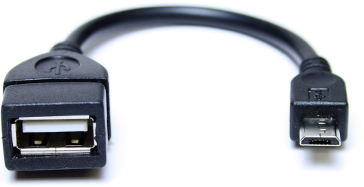
Android phones include On The Go (OTG) technology. It is a chip or chip peripheral implementing the USB port that can shift between client and host mode. In other words, more or less any Android device could use the USB connection — with a special USB adapter (see Figure 3-2) — to connect standard HID USB devices like keyboards and mice.
FIGURE 3-2: The cable to use phones under host mode with HID USB devices
Most people identify keyboards as just input devices, but a standard computer keyboard comes with some LEDs used to indicate the status of the different LOCK keys. From this point of view, a computer keyboard is actually an input/output device.
It is possible to reprogram the firmware of your Arduino Uno or Arduino Mega ADK to behave like a keyboard. It is therefore possible to use a self-made keyboard-like device to communicate with your Android device.
Phones are not easy to deal with when it comes to using the Host Mode. This is not a standard feature of the Android OS and the examples you can find are about hacking the phone’s kernel. On the other hand, some tablets come equipped with double micro USB connectors, one being the standard Android port and the other one a standard USB Host port. An example of this can be seen in Figure 3-3.
FIGURE 3-3: Tablet with multiple USB connectors with an Arduino Uno acting as a keyboard

TCP/IP
Probably the most obvious way to get your Android device to communicate with the physical world is to get it to talk to a connected object. You could use your Arduino hooked to a series of shields that would offer connectivity to some sort of network.
Among others, you could use:
- An Arduino Ethernet Shield (Figure 3-4) or equivalent. These boards enable you to connect to a wired network and connect to a server to post data, or even create a small server to which you could connect with your Android device via a browser. An equivalent use scenario would be using an Arduino Ethernet board, which merges an Arduino Uno together with an Ethernet Shield into a single circuit.
FIGURE 3-4: Arduino Uno with an Ethernet Shield

- An Arduino GSM/GPRS Shield (Figure 3-5) or compatible. With this you can connect to the Internet to post data to servers. Again, you could connect to the data posted by the board by sending requests to the server. It would also be possible to send data from the phone to the board via the intermediating server.
FIGURE 3-5: Arduino Uno with an GSM/GPRS Shield

- An Arduino Wi-Fi Shield (Figure 3-6). It is completely equivalent to the Arduino Ethernet Shield case, but operates over a Wi-Fi connection. In the same way as with the Ethernet Shield, you do not necessarily need a server between the Android device and your Arduino board. One of them could operate as server and the other as a client in a typical TCP/IP connection.
FIGURE 3-6: Arduino Uno with a Wi-Fi Shield

Audio Port
Phones have audio ports that include a microphone and two audio out lines (one for the left audio channel and one for the right one). It is therefore possible to create a DTMF-like communication between the Android device and an external circuit.
There is a very interesting implementation of this concept of connecting Arduino boards with Android devices over the audio port using frequency-shift keying (FSK)-encoded tones. Visit the Androino Terminal Project on Google Code at http://code.google.com/p/androino/wiki/AndroinoTerminal for more information.
Bluetooth Options
The early implementations of the AOA didn’t include the possibility of creating accessories over Bluetooth. Also, until the deployment of Froyo (codename for Android’s release 2.2), there was no way for the developers to even access the Bluetooth port in the phones and tablets running Android.
From the moment Froyo was released, you could develop applications that could connect to Android devices. The applications could call the basic functions within the operating system to pair to Bluetooth devices and open a transparent serial port connection to them. It is possible to, for example, use the Arduino Bluetooth board to connect to the phone wirelessly. An example of this is shown in Figure 3-7, where you can see the Nexus One, an Arduino Bluetooth board, and a specially made shield to control up to six motors using the PWM-enabled pins on the board.
FIGURE 3-7: Arduino Bluetooth board with homebrew shield.

Any of the above mentioned techniques refer to which is the physical transmission channel the information will be sent through. MQTT operates on top of any of them. MQTT adds structure to the data, in other words, adds headers that will help the receiver classifying the data.
INTRODUCING MQTT
The Message Queue (MQTT) protocol was invented by Andy Standford-Clark and Arlen Nipper at IBM redundant in 1999. Back in those days, as you might recall, bandwidth was quite a scarce commodity, especially the stable kind. If the wired networking was quite poor back then, the wireless was a disaster. This, coupled with the need to remotely monitor and control devices and sensors, led these two gentlemen on a siege to overcome unstable remote monitoring — thus, MQTT came about.
MQTT is a protocol designed for communication on low-bandwidth, high-latency wireless networks. Its properties make it an ideal choice for applications in the world of connected devices, or, as you may know it better, the Internet of Things.
Another key feature of the MQTT protocol is scalability; it supports literally thousands of concurrent connections through a publish/subscribe messaging broker that lies at the heart of the MQTT system. This scalability is one of the reasons that Facebook chose to use it for its instant messaging system. In this book, however, you use just the one connection between an Android device and an accessory built using Arduino.
FIGURE 3-8: Publish/Subscribe pattern

We thought it would be an interesting challenge to bring it up as a way to implement the data exchanges happening between your accessory (made with an Arduino board) and the phone itself. This one-to-one communication can be seen as a peer-to-peer MQTT (P2P-MQTT), which can transcend beyond devices because the information is already encapsulated in the right format. In other words, you could use the phone to relay the information coming from the sensors to MQTT brokers that are part of a larger infrastructure.
You might ask yourself just how this protocol relates to AOA and Arduino. Because MQTT is designed to be lightweight and with a small footprint, it’s an ideal candidate not only for remote monitoring of sensors and instant messaging chat systems, but its specific properties also make it an obvious candidate for the types of projects that you build in this book. Some of the features of MQTT include the following:
- To allow for a wide range of applications, the content of the MQTT message that is being sent doesn’t matter one little bit (pun intended). The payload of each MQTT message is actually just that, a collection of bits and bytes. You, as the sender/receiver, will decide what those bytes mean.
- To limit the amount of data being sent, MQTT has been designed with an overhead of as small as 2 bytes per packet! Don’t be fooled, though; although 2 bytes is a very small overhead, most MQTT messages have an overhead that is a little bit bigger than that. The only message that comes to mind with as little as 2 bytes is the PINGREQ message.
- You’ve surely experienced a network disconnection at least once — if it was because of poor wireless coverage or a broken DSL modem, we’ve all been there. Today, everyone experiences these kinds of seemingly random disconnections, and what’s worse is that there’s not much you can do to avoid them. MQTT, however, has built-in ways of handling these kinds of disconnections gracefully, which is kind of awesome if you’re building an application dependent on networking.
For all of these reasons and more, MQTT makes an excellent candidate for use in many machine-to-machine (M2M) scenarios. You can find more information, and the open specifications, on MQTT at http://mqtt.org/.
Heads Up!
As described earlier, the header of a communications protocol describes how the recipient should decipher the message. In MQTT the overhead actually has two parts. The first part is called the fixed header and it’s required by all MQTT messages. It’s used to describe the general properties of the message. Table 3-2 shows an example of a fixed header.
TABLE 3-2: Fixed Header

The first byte of the fixed header has four different values that are interesting to us. First there’s the message type, which occupies the last four bits, then three flags that give the message extended properties beyond the message type — DUP, QoS, and RETAIN.
Although MQTT has a very small footprint, it doesn’t limit the message size very much; as a matter of fact, you can send single messages that are carrying up to 256MB of payload each. This is possible because of the Remaining Length field that tells you how many bytes the payload contains; this field can extend over 4 bytes in total.
The second part of the overhead is called the variable header and it’s needed only in certain types of MQTT messages. As the name implies, the format of the variable header doesn’t always look the same; it depends on the message being sent. As an example, when attempting to connect to a MQTT broker you also need to say what version of the MQTT protocol you’re using. This would be sent as an 8-bit unsigned value in the variable header attached in between the fixed header and the payload.
Message Type
MQTT defines fourteen different message types; each responds to a specific action being taken by one of the parties. For example, if your client application wants to connect to a broker, it would first send the CONNECT message and wait for the CONNACK response from the server before proceeding to publish or subscribe. Table 3-3 lists the different MQTT message types.
TABLE 3-3: MQTT Message Types
| MNEMONIC | ENUMERATION | DESCRIPTION |
| Reserved | 0 | Reserved |
| CONNECT | 1 | Client request to connect to Server |
| CONNACK | 2 | Connect Acknowledgement |
| PUBLISH | 3 | Publish Message |
| PUBACK | 4 | Publish Acknowledgement |
| PUBREC | 5 | Publish Received |
| PUBREL | 6 | Publish Release |
| PUBCOMP | 7 | Publish Complete |
| SUBSCRIBE | 8 | Client Subscribe Request |
| SUBACK | 9 | Subscribe Acknowledgement |
| UNSUBSCRIBE | 10 | Client Unsubscribe Request |
| UNSUBACK | 11 | Unsubscribe Acknowledgement |
| PINGREQ | 12 | PING Request |
| PINGRESP | 13 | PING Response |
| DISCONNECT | 14 | Client is Disconnecting |
| Reserved | 15 | Reserved |
MQTT V3.1 Protocol Specification
Quality of Service (QoS)
Because MQTT has such a wide range of uses, it’s imperative that you can choose different service qualities that define how the message will be delivered by the system. Three different levels are defined in MQTT:
- The lowest quality level sees the message sent once, without any sort of confirmation that it has arrived properly. This quality of service has the value 0 and is called AT MOST ONCE.
- The middle quality level sees the message being delivered at least once. It manages this by demanding an acknowledgment from the recipient that the message was received; the sender will just keep sending the same message until it gets an acknowledgment. It’s called AT LEAST ONCE and has the value 1. As you probably realize, this may cause problems when it comes to funky networking — a message may very well be delivered multiple times.
- The highest quality service level means that the message will be delivered exactly once, not more, not less, using a series of handshakes. This level is called EXACTLY ONCE and has the value 2.
You can also subscribe to messages based on their Quality of Service (QoS). If you subscribe to the second service level (middle level) you’ll only receive messages on that level or below. Any messages above your requested level will be downgraded to match your requested level; this means you will always get all messages on the topic you subscribe, no matter what level they’re at.
A published message QoS level may be downgraded by the broker, however it may never be upgraded by the broker.
Duplicate Delivery (DUP)
A message that has already been sent at least once should always be marked as duplicate using the DUP flag in the fixed header. This is used only for certain messages that have QoS level 2 or above; however, not all messages of QoS level 2 or above will be marked as duplicate.
Retain
When publishing a new message the client has the choice to let this message be saved by the broker for some reason. It’s important to realize that the broker will retain only one message at a time for a specific topic (often you’d use one topic per sensor, so in reality each sensor can retain its last known value on the broker). If the broker already has a message retained and is asked to retain a new message, the old message is deleted. This can be very useful for sensors that rarely publish new values, but you still want the client to get a value when connecting, or if the value being published is very important.
Remaining Length
This is the last value of the fixed header. In MQTT most messages have a payload, and that payload has a certain size in bytes; this is what the Remaining Length field is used for. It tells the receiver how many bytes to expect after the overhead for a certain message. Be wary, though; the Remaining Length field has some funky rules that you should grasp on at least a basic level:
- It’s part of the fixed header.
- It uses between 1 and 4 bytes.
- It represents a payload size of up to 256MB.
The way this works is that if the payload is less than or exactly 127-bytes long, the Remaining Length field uses only 1 byte and it uses all 8 bits of that byte. However, if the payload is anything above 127 bytes, it may use up to 4 bytes, where only 7 bits of each byte is used to describe the length. The eighth bit is used to define if another byte should be expected. Figure 3-9 describes the procedure of calculating the remaining length.
FIGURE 3-9: Remaining length composition

MQTT Messages
Before moving on to defining the use of your very own protocol based on MQTT, this section reviews a few of the most common messages that you’ll use when building the communication library used for this book.
Connect
The CONNECT message is a request sent by a client wanting to connect to the MQTT broker. It should be sent right after the client established a physical connection to the broker; if it’s not sent, the broker should terminate the connection. At a very minimum, the CONNECT message contains a unique identifier for the client called the client ID. It can also carry more detailed information regarding the client wanting to connect, such as username, password, and so on.
When a broker receives a CONNECT message, it immediately sends a CONNACK message back to the client acknowledging that the first message was received, and some extra information regarding the acceptance of the connection. If the client doesn’t get this message, it should terminate the connection. Table 3-4 shows an example variable header for the CONNECT message. Notice that Byte 10 contains settings for the CONNECT message. For example, if the CONNECT message contains a username and password, but it doesn’t contain the actual username and password, those are sent as part of the payload.
TABLE 3-4: Example Variable Header for the CONNECT Message
| DESCRIPTION | |
| Protocol Name | |
| Byte 1 | Length MSB (0x00) |
| Byte 2 | Length LSB (0x06) |
| Byte 3 | M (0x4D) |
| Byte 4 | Q (0x44) |
| Byte 5 | I (0x49) |
| Byte 6 | s (0x73) |
| Byte 7 | d (0x64) |
| Byte 8 | p (0x70) |
| Protocol Version Number | |
| Byte 9 | Version 3 (0x03) |
| Connect Flags | |
| Byte 10 | Has Username, Has Password, Will Retain, Will QoS, Will, Clean Session (0xCE) |
| Keep Alive Timer | |
| Byte 11 | Keep Alive MSB (0x00) |
| Byte 12 | Keep Alive LSB (0x0A) |
MQTT V3.1 Protocol Specification
Connection Acknowledgment
When the broker receives a connection request, it has to send an acknowledgment of this request back to the client. If it fails to send this acknowledgment within a reasonable timeframe, the client will gracefully disconnect. On the other hand, if the broker doesn’t even receive a connect request from a client when connecting, it should also terminate the connection gracefully. This way it’s up to both parties to play nice with each other for a connection to happen.
The variable header of the CONNACK message contains a code for the client to decipher, as described in Table 3-5.
TABLE 3-5: CONNACK Response Code
| ENUMERATION | HEX | MEANING |
| 0 | 0x00 | Connection Accepted |
| 1 | 0x01 | Connection Refused: unacceptable protocol version |
| 2 | 0x02 | Connection Refused: identifier rejected |
| 3 | 0x03 | Connection Refused: server unavailable |
| 4 | 0x04 | Connection Refused: bad username or password |
| 5 | 0x05 | Connection Refused: not authorized |
| 6-255 | Reserved |
MQTT V3.1 Protocol Specification
Table 3-6 shows an example variable header for the CONNACK message.
TABLE 3-6: Example Variable Header for the CONNACK Message
| DESCRIPTION | |
| Byte 1 | Reserved, not used |
| Byte 2 | Return Code |
MQTT V3.1 Protocol Specification
Publish
When the client wants to distribute any type of information, it sends a PUBLISH message to the message broker, which then distributes this message to all clients that are subscribed to that topic.
The QoS for a topic is determined in the fixed header of the PUBLISH message. As mentioned earlier, no matter the QoS for a topic, the subscribers will always receive all the messages for that topic.
The PUBLISH message can take advantage of all the extra parameters in the fixed header, and it also has a variable header with extra information regarding the message being sent; such as the topic and message ID. Table 3-7 shows an example.
TABLE 3-7: Example Variable Header for the PUBLISH Message
| Description | |
| Topic Identifier | |
| Byte 1 | Length MSB (0x00) |
| Byte 2 | Length LSB (0x03) |
| Byte 3 | a (0x61) |
| Byte 4 | / (0x2F) |
| Byte 5 | b (0x62) |
| Unique Message Identifier | |
| Byte 6 | Message ID MSB (0x00) |
| Byte 7 | Message ID LSB (0x0A) |
MQTT V3.1 Protocol Specification
The message identifier in the variable header is unique only for the client, so it’s up to the client to give the message a unique ID number. Because the unique identifier is always 16 bytes long, the system can support up to 65,535 unique messages per client at any one time. The client can, of course, also reuse message IDs that have been sent already, and because of this it’s highly unlikely that any two message IDs will interfere with each other.
Publish Acknowledgment
Because the PUBLISH message can have any of the three QoS levels, it must also have different acknowledgment methods. The first quality of service level, 0, has no acknowledgment. The second level, 1, keeps sending the message until an acknowledgment has been received. Table 3-8 shows an example variable header for the PUBACK message.
TABLE 3-8: Example Variable Header for the PUBACK Message
| Description | |
| Byte 1 | Message ID MSB (0x00) |
| Byte 2 | Message ID LSB (0x0A) |
MQTT V3.1 Protocol Specification
The third level, level 2, has an advanced multi-message handshake to make sure that the message was sent, and received, exactly once. You won’t be implementing this level while reading this book. If you’re interested in more reliable communication, you should read more about MQTT.
Subscribe
If your application is interested in reading information published by others, it has to subscribe to a certain channel or topic. This tells the message broker that your application is interested in certain information, and if it qualifies for this information based on some criteria such as username and password, it will be eligible for those messages. If, however, the client doesn’t fulfill the needed criteria, the broker has no obligation to tell the client this.
The only thing present in the SUBSCRIBE variable header is the message ID; it has this ID because it expects a SUBACK message in response from the broker, meaning that it has QoS level 1. Table 3-9 shows an example variable header for the SUBSCRIBE message.
TABLE 3-9: Example Variable Header for the SUBSCRIBE Message
| Description | |
| Message Identifier | |
| Byte 1 | Message ID MSB (0x00) |
| Byte 2 | Message ID LSB (0x0A) |
MQTT V3.1 Protocol Specification
The payload of the subscribe message contains the topics to subscribe to and the quality of service for each of those topics.
Unsubscribe
Unsubscribe is sent by a client that isn’t interested in receiving any more updates for a certain topic. It has its own acknowledgment part, which needs to be sent by the broker to acknowledge that the unsubscribe was successful.
The overhead of the unsubscribe message is almost identical to that of the subscribe message. The only difference is the message type in the fixed header; the variable header looks exactly the same as in the subscribe message. The payload, however, has a small difference; where the subscribe message has both Topic and Quality of Service, the unsubscribe message has only the Topic part. This is because the broker doesn’t need to know what QoS the client requested for the particular subscription, only that the subscription should be removed.
Ping
Commonly, ping is as tool used to detect broken pipes in networking or to measure latency over connections. In MQTT, the PINGREQ message is used as an indicator that you’re still alive, and it’s used only when no other information has been sent for a certain period of time. Although the PINGREQ message expects a response from the broker, it doesn’t require one, which is why the QoS isn’t used in this message (unlike the SUBSCRIBE message, which is defined as a QoS level 1 message).
The PINGREQ message has no payload or variable header, and it uses none of the extra parameters of the fixed header. This makes it the smallest MQTT message.
P2PMQTT: A MODIFIED MQTT
In this book you’ll develop a new protocol called peer-to-peer MQTT (P2PMQTT) based on the standard MQTT v3.1 specification. Because MQTT was originally intended for use in a one-to-many publish/subscribe pattern in which messages always pass through a broker before delivery, you need to modify the use case a little bit before applying it in the new peer-to-peer context.
You won’t change the rules of how a message should be packaged. The messages will remain identical to the specification discussed earlier in this chapter, so the major difference lies in how you implement MQTT. Instead of letting a message broker handle the distribution of messages, your two clients — the Android device and the Arduino accessory — each takes some responsibility of the broker, thereby removing the need for having a broker in the system.
Establishing a Connection
In the standard MQTT system, you’d see an always-online message broker at the core of the entire system; MQTT clients would create a connection to this broker. When the client successfully connects to the message broker, meaning the physical connection is established, the client sends a connection request that can contain a number of parameters such as username and password. The broker then responds accordingly.
However, in our slightly modified version of the MQTT protocol, there is no central messaging broker, so the responsibility of handling connections falls to the clients. Each client then needs to do the following:
- Send a CONNECT request message when a connection is established.
- Terminate connections that aren’t followed by a connection request by the other party.
- Send the CONNACK message when a CONNECT message is received.
Subscribing to a Topic
Subscribing means the same thing as it does in the normal MQTT system. Each client handles a list of connected peers and their respective subscriptions. If a client isn’t interested in a particular topic, the client can at any time during the connection send an unsubscribe message.
Using this approach in an accessory context limits the amount of unnecessary data being transmitted. For example, your particular accessory might support multiple sensors and actuators, but not all the sensors and actuators are active at the same time. In this situation, both the Arduino client and the Android client need to do the following:
- Maintain a list of subscriptions for all the other parties connected; right now Android supports only one accessory at a time, but this will likely change in the future.
- Send and listen for SUBSCRIBE messages; the client should send a subscribe when interested in receiving messages of a certain topic.
- Send UNSUBSCRIBE messages when no longer interested in receiving messages of a certain topic.
- Listen for, and send, UNSUBACK when appropriate.
- Listen for, and send, SUBACK messages when appropriate.
Publishing a Message
The most interesting message of them all, the PUBLISH message, contains the content of the message in which you’re interested. In the normal MQTT system, the broker receives a great deal of messages from clients that care less about who receives it. However, in your broker-less environment the clients will maintain the list of subscriptions themselves, and because of this only publish messages according to that list.
You could of course also make the subscription handling local instead, making each client maintain their own list of subscriptions; only reacting to the messages they’re interested in and ignoring all other messages. However, this would potentially add a lot of unnecessary traffic between the devices as the sending party cares less about who is interested in the message and more about sending the message.
Disconnecting
Disconnecting in the P2PMQTT is identical to the DISCONNECT message as defined in the standard specification. Although it’s used differently, both sides should send the disconnect when they’re about to cancel the connection. A good example of this is in the onDestroy lifecycle method in Android. The party sending the DISCONNECT message shouldn’t expect anything in return, it’s just a pleasant notice to the other party saying, “Hey dude, I’m about to drop the connection. Clean up after me!”
The “clean up after me” part at the end is fairly important because you should never expect the other party to clean up after itself. All data transfers should be stopped, and sockets should be closed when the DISCONNECT message is received.
SUMMARY
Data communication refers to the exchange of information between systems. The communication itself is commanded by protocols, and different scenarios of use require different techniques. Wireless communication with high environmental noise will, for example, require using more bytes to detect errors, whereas short-distance wired communication will rely on more simple protocols.
Message Queue Telemetry Transport (MQTT) is a messaging system built mainly for low-bandwidth remote sensor systems. While MQTT doesn’t inherently contain any package error checking such as a checksum, it has an attribute called Quality of Service (QoS) which defines an expected level of quality for any given message. This quality level will tell both the publisher and the broker (in your context the receiver) how to act to deliver the message properly.
The standard MQTT implementation relies on one central messaging broker that handles connections and distributes all messages to any interested clients. In your context, however, there is no messaging broker, and instead, the two clients of the accessory network will both share the responsibilities of the messaging broker, including handling connections and maintaining subscriptions.
MQTT messages are constructed in three parts:
To enable the best performance on these low-bandwidth and unreliable networks MQTT has been constructed with a set of features. Some of the more important features of MQTT include:
Of course, MQTT has more features than these, and you should definitely explore the MQTT specification in detail. You can find it at: http://mqtt.org/.