
Chapter 2
Samuel Morse and the Telegraph

Prior to Samuel F. B. Morse’s invention of the electric telegraph, there was no good way to communicate information across distance at any speed greater than that of a horserider. Sure, there were some limited experiments. Men holding flags called semaphores stood on hilltops and noted one another’s coded movements through spyglasses. This was clumsy and slow. Worse, it was incredibly expensive because it required a lot of men on a lot of hilltops to relay messages over any substantial distance.
In the 1820s and early 1830s, Samuel F. B. Morse was well known as an accomplished painter; he was praised by artistic luminaries of the time: Gilbert Stuart, Benjamin West, and Washington Allston. In 1830, Morse left his home in New York for Europe, intending to refine his skills even further by studying with the masters of Italy, Switzerland, and France. But while he was there, painting began to lose its hold over the ever-restless Morse. Although he was at the height of his artistic prowess, other ideas of how he might spend his life apparently began to encroach upon his thoughts.
From Artist to Inventor
In 1832, Morse boarded the packet boat Sully with his brushes and canvases and cruised westward across the Atlantic. While on board, Morse chanced upon a conversation with other passengers about the era’s hot science topic—electromagnetism. What he heard fascinated him. More than that, this moment became a turning point not only in his life, but in the future of communications technology. Morse had boarded the ship an uninspired artist; he left it aspiring to be an inventor. As he left, he told the ship’s captain, “Well, Captain Pell, should you ever hear of the telegraph one of these days as the wonder of the world, remember the discovery was made on the good ship Sully.”
Despite the fact that he had little, if any, knowledge of electricity prior to this point, he plunged ahead as only a man in the throes of a serious midlife career crisis can. His lack of education and preparation in this field quickly became evident. In his crude laboratory, his homemade batteries had little or no energy, his elementary attempts at electromagnets produced no magnetism, and he didn’t even understand the role of insulation on wires.
But Morse did have two important assets. He had plenty of determination, and he had smart friends. By asking the right questions of his friend Leonard Gale, a chemistry professor at New York University, he was able to make headway, building a telegraph capable of sending messages a quarter mile. A few years later, he asked the right questions of Gale’s friend Joseph Henry, who was perhaps the most important American scientist living in the period between Benjamin Franklin and Thomas Edison. Armed with Henry’s answers, Morse was able to design a workable long-distance telegraphy system.
In 1843, Morse received the then huge sum of $30,000 from the federal government to construct the first long-distance telegraph line, stretching from Washington, D.C., to Baltimore, MD, along the railroad tracks belonging to the B&O Railroad. The wires were strung from poles and trees along the right-of-way, insulated from the ground by crude insulators made from broken glass bottles. On May 24, 1844, the first telegraph message, “WHAT HATH GOD WROUGHT,” was tapped from the B&O’s Mount Clare Station in Baltimore to the Capitol Building in Washington. The era of electronic, high-speed information transfer had begun.
Making a Morse-Style Telegraph
You can make a telegraph system to communicate with friends, to practice Morse code, or simply to get a better appreciation for Samuel Morse and his world-changing invention. A telegraph system similar to the one Morse demonstrated in 1844 consists of four parts: the key, the sounder, the battery, and the wire.
In telegraphy, the key is a spring-loaded lever. When the telegraph operator presses the key, it completes an electrical circuit to the sounder, which is an electromagnet that pulls a steel plunger against a hard surface to make an audible click. The battery supplies the electrical voltage for the electromagnet, and the wire connects all of these items together.
Making the Key
Telegraph Key Directions
Follow these steps to construct the telegraph key:
- To begin, you’ll need to assemble the key’s lever or tapper. To do so, line up the aluminum angle iron with the ½-inch square dowel along its length and then glue it to the dowel shown in Figure 2-1.

Figure 2-1: The aluminum angle iron glued to the dowel
- When the glue is dry, drill a centered 3/16-inch hole through the lever/tapper for the knob screw ¼ of an inch from the end of the dowel (usually the knob screw is a #8 machine screw, but check your knob before you drill) as shown in Figure 2-2.

Figure 2-2: Drilling the hole for the knob screw
- Next, drill a centered 1/8-inch hole in the side of the lever/tapper, 2 inches from the same end of the dowel as the knob screw hole, as shown in Figure 2-3.
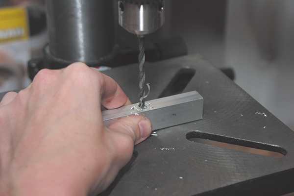
Figure 2-3: Hole in the telegraph’s tapper
- Attach the tapper knob as shown in Figure 2-4.

Figure 2-4: Attaching the knob
This completes the lever/tapper. Set this aside for now so you can begin working on the telegraph key base.
- Refer to Figure 2-5, which shows the telegraph key’s base, for a visual and drill the following holes.

Figure 2-5: Top view of the telegraph block (just holes)
- As shown in Figure 2-5A, drill a centered 5/16-inch-diameter hole (labeled “B” in Figure 2-5) 2 inches from the edge of the board for the dowel that will hold the spring.

Figure 2-5A: Drilling a 5/16-inch hole
Glue the 5/16-inch round wooden dowel into the hole. The dowel end should extend about ¼ inch above the surface of the block. When the glue is dry, place the spring over the dowel as shown in Figure 2-5B.
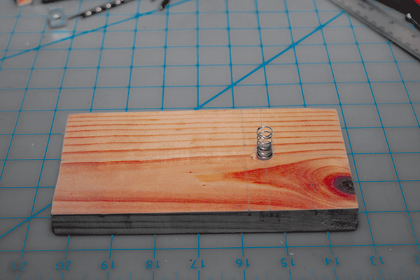
Figure 2-5B: Placing the spring
- Using the steel mending plate as a guide, drill two 1/8-inch pilot holes (labeled “A” in Figure 2-5) for the #8 round head wood screws 1 inch from the edge of the 7-inch-long 1×4 wooden board.
- As shown in Figure 2-5C, drill two more 1/8-inch pilot holes (labeled “C” in Figure 2-5) 2½ inches from the edge of the 1×4 for the corner braces. The holes should be placed so the vertical sections of the corner braces are 1 inch apart.

Figure 2-5C: Drilling two pilot holes
- As shown in Figure 2-5A, drill a centered 5/16-inch-diameter hole (labeled “B” in Figure 2-5) 2 inches from the edge of the board for the dowel that will hold the spring.
- Now attach the 2-inch-long steel mending plate to the telegraph key base with the round head screws using the pilot holes you drilled in step 4 (see Figure 2-6).

Figure 2-6: Mending plate attached
- Then attach the ¾-inch by ¾-inch corner braces to the wood block with the #8 flat head wood screws using the pilot holes you drilled in step 4c.
The partially assembled telegraph key should look like Figure 2-7.
- To assemble the two parts of the telegraph key block (the tapper and the base), insert the 1¼-inch #8 machine screw through the hole in one of the ¾-inch corner braces, into the hole you drilled through the tapper in step 3, and then into the other corner brace.
Figure 2-7: The partially assembled telegraph key
- When you’ve got everything lined up, attach the wing nut.
When you’re done, your telegraph key should look like the one in Figure 2-8.


Figure 2-8: Completed telegraph key
Making the Sounder
The next step to assembling your telegraph system is to construct the sounder.
Sounder Directions
Follow these steps to assemble your sounder:
- Drill holes on the faces of the wooden boards and metal strips as indicated in Figures 2-9 and 2-10.

Figure 2-9: Arial view of the sounder block assembly
- Fasten the 1×4 and 2×4 boards together with their edges lined up using nails or deck screws, as shown in Figure 2-11.

Figure 2-10: Side view of the sounder block assembly

Figure 2-11: Joining the 1×4 and 2×4 boards
- Place the 5/16-inch bolt in the chuck of your drill so that 1 inch of screw thread is exposed.

- Leaving about 1 foot of wire trailing, wrap the magnet wire around the threads closest to the head of the drill.
- With a helper holding the magnet wire spool so it is free to spin, start the drill and wrap the wire around the bolt, using an up and down motion so the wire turns are distributed as evenly as possible. Stop winding when there is a foot of wire left and tie it off so it does not unravel (see Figures 2-12 and 2-13).

Figure 2-12: Wrapping the magnet wire around the bolt to make your electromagnet

Figure 2-13: A close-up of the wrapped wire
- Screw the electromagnet into the 5/16-inch hole you drilled in the 1×4 in step 1 to a depth of about ¼ inch. (Since the screw is much harder than the wood, you should be able to screw the bolt in fairly easily without needing to tap the hole first.)

- Screw both of the 3½-inch-long steel strips onto the 2×4, as shown in Figure 2-9, but don’t screw them tight—leave enough space for the 12-inch metal strip to slide underneath.
- Insert the 12-inch-long steel strip between the 3½-inch metal strips and the 2×4. Center the long strip on the 2×4 and tighten the screws attached to the 3½-inch-long steel strips slightly.
The completed sounder look should like Figure 2-14.

Figure 2-14: The completed sounder
Wiring the Telegraph
Now that you’ve completed the assembly of both the key and the sounder, it’s time to wire your telegraph system (as shown in Figures 2-15 and 2-16.

Figure 2-15: A diagram showing how to wire the key and sounder
Figure 2-16: This photo shows what the system looks like after it is wired.
After you’ve wired your system, adjust the placement of the 12-inch strip on the sounder so it responds quickly and precisely when the telegraph key is closed. When you have it well adjusted, tighten down the cross strips to hold it fast.
How the Telegraph Works
Basically, the telegraph is a pair of electromagnets attached to spring-operated switches. As Figure 2-17 shows, when the key is pressed, the circuit is completed, causing the sounder electromagnet on the distant end to energize and make a click sound. When the key is released, the sounder springs back up.
It takes a fair amount of electrical energy to operate long-distance telegraph electromagnets because the telegraph wire does have some electrical resistance, and over long distances, that adds up. One of the important ways Morse made the telegraph work over long distances was by incorporating Joseph Henry’s electromagnetic relay, which allowed for the use of large storage batteries along the telegraph line.

Figure 2-17: Explanation of how the telegraph works
A relay is a switch that opens or closes an electrical circuit based on input from another circuit. That means a small, nimble switch like a telegraph key can, with the use of a relay, control a big, long-distance telegraph circuit with the sounder located hundreds of miles away.
With multiple relays, electrical signals can travel any distance and arrive at the receiving station with nearly as much power as they had when they were transmitted.
Morse Code
Since the telegraph transmits clicks, not speech, Samuel Morse had to invent a system or code in which alphabet letters and numbers are represented by combinations of long and short sound telegraph signals. Figure 2-18 shows the long and short of Morse code.
Study Figure 2-18; once you learn the code, you can understand the following joke. The periods represent dots and the hyphens are dashes; the slashes separate the words in the sentence; and the second “letter” (---…) is a colon.
--.- ---... / .-- .... .- - / -.. --- / -.-- --- ..- / --. . - / .. ..-. / -.-- --- ..- / -.-. .-. --- ... ... / .- / .--. .- .-. .-. --- - / .-- .. - .... / .- / .-- --- --- -.. .--. . -.-. -.- . .-. ..--.. / .- ---... / .- / -... .. .-. -.. / - .... .- - / - .- .-.. -.- ... / .. -. / -- --- .-. ... . / -.-. --- -.. .

Figure 2-18: Morse code