
Chapter 3
Squire Whipple and the Truss Bridge

All mechanical, civil, and aerospace engineers learn how to analyze structures early in their engineering training. Determining the size and direction of compressive or tension forces acting on each piece of a large construction is a civil engineering discipline called statics. With this basic knowledge, engineers figure out the right sizes, shapes, and thicknesses of materials they use to build houses, dams, bridges, buildings, and other nonmoving structures.
When studying statics, engineering students learn about many architectural elements that are designed to hold things up against the forces of gravity—arches, beams, buttresses, and vaults, to name a few. The truss is one of the most important of the basic building elements and it’s widely used in construction. In its simplest form, a truss is merely a rigid framework of bolted-together triangles. Triangles are inherently strong and stable, and structures made out of them are also strong, rigid, and lightweight.
The Origin of the Truss
Who first figured out how to build with trusses? It’s hard to say. Certainly, the practice has been around for a long time, but the archeological records are too sketchy to tell us exactly who came up with the idea. It’s clear that the classical Greeks, for all their genius in other fields, didn’t know much, if anything, about building with triangle trusses. The Romans may have dabbled with them, but examples of Roman buildings and viaducts that use them are few and far between.
But something must have happened during the early period of the Dark Ages that followed the fall of the Roman Empire, because later in Medieval times, the truss was well known to builders. Medieval cathedral and church architects empirically, if not scientifically, understood the technique of truss building, and there are plenty of examples of early European buildings in which wooden triangular trusses hold up the roof.
However, really understanding the physics behind the truss took a long while to come about. Engineering practice in both the Middle Ages and Enlightenment was not analytical or based on scientific knowledge as much as it was empirical and experience based. Today, structures like bridges are designed using science. Knowing how to design a truss scientifically is an important skill for which engineers can thank New York civil engineer Squire Whipple (Squire was his first name, not his title), who developed the first method for analyzing and designing trusses.
In 1841, Whipple published A Work on Bridge Building, which revolutionized the field of civil engineering. No longer would builders use “rules of thumb” to guess at how big and thick to make a strut or girder. Now, because of Whipple’s work, they knew exactly.
Whipple and the Design of Structures
Prior to the publication of this book in 1841, Whipple was busy. During this time, he figured out how to analyze the forces acting on a stationary object using a graphical method of lining up, head-to-toe, representations of the size and directions of forces that he called the polygon of forces. Nothing of this method depended on complex math, just the clever use of rulers and protractors on graph paper.
A structure such as a bridge is subject to many different simultaneous forces. At any chosen point on the structure, each of those forces can be represented by an arrow of a fixed length and direction. Whipple determined that you can take all those force arrows, called vectors, and line them up, head to toe, to make an open-sided polygon. The vector required to close the polygon is called the resultant, and the length and direction of the resultant is the net force on the structure at that location.
To make his method work, Whipple made a number of assumptions. Most important is the assumption that all connections are pinned rather than fixed and are free to rotate. (This is not really how bridges are typically built. Normally, steel gusset plates are used to connect one member to another, and they are solidly riveted, so no rotation is possible. But this assumption makes little difference to the accuracy of calculations in most cases, and it greatly simplifies matters by ensuring that all forces on all members are applied parallel to the centerline of the member.)
Whipple designed a number of bridges during his career. One of his designs, a bowstring-shaped truss bridge made of cast iron, became the standard design for bridges over the Erie Canal. For his contributions, the Society of American Civil Engineers declared Whipple the “father of American iron bridge building.”
The publication of Whipple’s book set off a boom in civil engineering projects. Because this concept wasn’t so hard to understand and didn’t require them to know complex math like calculus or trigonometry, engineers quickly picked up on this knowledge, and with the polygon of forces at their disposal, they began to safely and economically design viable truss bridges out of wood and steel members.
Soon after this publication, the great age of iron bridge building was in full swing. The triangle structure of the truss is obvious in the beautiful spans of the Navajo Bridge over the Colorado River in northern Arizona, the Whirlpool Rapids Bridge over Niagara Falls, and the Quebec Bridge over the St. Lawrence River. But hidden trusses are also important parts of suspension and cantilevered bridges such as the Brooklyn Bridge in New York (see Figure 3-1).

Figure 3-1: Examples of truss bridges
Building a Warren Truss Bridge
There are many different types of truss bridges, and each type is typically named after the engineer who first devised it, but they all were influenced by Whipple’s work. The simplest bridges are the Howe, the Pratt, and the Warren, all shown in Figure 3-2.

Figure 3-2: Truss types
In 1848, English engineer James Warren designed the first truss bridge that consisted solely of equilateral triangles connected side by side. The design starts with a single triangle; the next triangle is inverted and connected to the first. The following triangle is again inverted and connected, and the structure continues in this manner across the span of water. Structural engineering doesn’t get much simpler than this, but the design of the Warren truss is also tried and true—it produces a bridge that is easy to build, strong, and relatively lightweight.
In this project, we’ll make a model Warren truss bridge. Light and strong, our bridge model can hold more than 100 pounds. If you build it very carefully, it can hold a lot more than that!
Constructing the Bridge
Now that you’ve assembled your supplies, it’s time to begin:
- Use the utility knife to cut the balsa wood into 14 squares measuring 2 inches on a side. These squares are the gusset plates for the bridge (see Figure 3-3).
- Using the craft sticks, gusset plates, glue gun, and glue, you’ll now build the two bridge sides. For the first side, using the masking tape, tape the gusset plates to your work surface. Then hot glue the craft sticks to the gussets as shown in Figure 3-4.
Take care to make the glued connections neat, and make sure you align the craft sticks to form exact equilateral triangles.

Figure 3-3: The gusset plates

Figure 3-4: Building the first of two bridge sides
- While the glue sets on the first bridge side, glue together the second side the same way.
- Once the glue sets on the first side, flip it over, and attach craft sticks to the other side in the same positions as you did with the first side.
- Do the same with the second truss (see Figure 3-5).
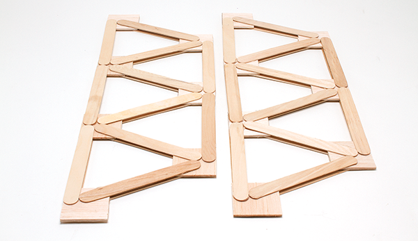
Figure 3-5: The completed pair of trusses
The long top and bottom members of the sides are called chords. The slanted pieces that tie the chords together are called struts or braces.
- If you use Squire Whipple’s polygon of forces method to analyze the forces in each member, you’ll find that the greatest forces are in the top and bottom chords, at the center of the bridge. So, to make your bridge its strongest, glue on an extra craft stick at those points to reinforce both trusses.
Now that you’ve got your trusses built, it’s time to move on to build the rest of your bridge structure.
- Place the bricks on your work surface 4 inches apart and make certain that their long sides are parallel.
- Tape each truss to one of the bricks.
- Using more craft sticks, glue the struts and braces across the top and bottom and ends of the bridge as shown in Figure 3-6.

Figure 3-6: Gluing the two trusses together
When you are finished connecting the two sides, your bridge should look similar to Figure 3-7.

Figure 3-7 :The finished bridge
Testing Your Truss Bridge
Now that you’ve got your bridge constructed, it’s time to see exactly how strong it is! Follow these steps to find out.
- Place the bricks 14 inches apart on the floor.
- Place the front and back edges of the bridge on the bricks (as in Figure 3-8).
- Load ’er up! You can use concrete blocks, barbell weights, buckets of water, or anything else flat and heavy (see Figures 3-8 and 3-9).

Figure 3-8: Bridge with load

Figure 3-9: Bridge with heavy load
Add weight slowly and incrementally and make sure you keep body parts like toes out from underneath the bridge. Keeping the weight evenly distributed will allow you to add more weight before the structure fails.
It’s your bridge, so you can either add weight until it eventually fails, or you can paint it and display it proudly as proof of your engineering abilities.
How Truss Bridges Stand
The reason engineers design structures with trusses is that they efficiently and inexpensively transfer weight from long, horizontal members to strong vertical ones. For example, a truss bridge transfers the weight of the cars driving over it to the bridge’s study pilings and piers. Similarly, the trusses holding up the roof of your house basically take the weight of the roof’s shingles and rafters and move it to the strong vertical posts and studs inside the walls. Because of the triangle-based geometry of the truss, they can be lightweight and relatively inexpensively. Figure 3-10 explains this in more detail.

Figure 3-10: How trusses work