10
ADVANCED DEVELOPMENT
10.1 REDUCING PROGRAM RISKS
The advanced development phase is that part of the system development cycle in which the great majority of the uncertainties inherent in the selected system concept are resolved through analysis, simulation, development, and prototyping. The principal purpose of the advanced development phase is to reduce the potential risks in the development of a new complex system to a level where the functional design of all previously unproven subsystems and components has been validated. At its conclusion, the risks of discovering serious problems must be sufficiently low that full-scale engineering may be begun with confidence. This phase’s primary objectives are to develop, where necessary, and validate a sound technical approach to the system design and to demonstrate it to those who must authorize the full-scale development of the system.
The general methodology of accomplishing risk reduction is discussed in Chapter 5 in the section on risk management. The components of risk management are described as risk assessment, in which risks are identified and their magnitude assessed, and risk mitigation, in which the potential damage to the development is eliminated or reduced. This chapter is concerned with typical sources of risks encountered in the early phases of developments of complex systems and the methods for their mitigation.
To accomplish the above objectives, the degree of definition of the system design and its description must be advanced from a system functional design to a physical system configuration consisting of proven components coupled with a design specification, to serve as the basis for the full-scale engineering of the system. In most new complex systems, this calls for mature designs of the subsystems and components. All ambiguities in the initial system requirements must be eliminated, and often, some of the more optimistic design goals of the original concept of the system must be significantly curtailed.
It should be noted that all new system developments do not have to go through a formal advanced development phase. If all major subsystems are directly derivable from proven predecessor or otherwise mature subsystems, and their characteristics can be reliably predicted, then the system development can proceed on to the engineering design phase. Such is the case with most new model automobiles, in which the great majority of components are directly related to those of previous models. In that case, such critical items as the airbag system or pollution control may be individually built and tested in parallel with the engineering of the new model.
Place of the Advanced Development Phase in the System Life Cycle
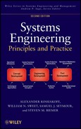
The advanced development phase marks the transition of the system development from the concept development to the engineering development stage. As seen in Figure 10.1, it follows the concept definition phase, from which it derives the inputs of system functional specifications and a defined system concept. Its outputs to the engineering design phase are system design specifications and a validated development model. It thus converts the requirements of what the system is to do and a conceptual approach of its configuration into a specification of generally how the required functions are to be implemented in hardware and software. Other required outputs, not shown in the figure, include an updated work breakdown structure (WBS), a revised systems engineering management plan (SEMP) or its equivalent, and related planning documents. Additionally, the system architecture is updated to reflect changes to date.

Figure 10.1. Advanced development phase in system life cycle.
As noted above, this phase is especially critical in the development of complex systems that involve extensive use of advanced technology and/or novel unproven concepts. It may require several years of intensive development effort before the new features are sufficiently mature and well demonstrated to warrant initiating full-scale engineering. In addition, it may also be necessary to develop new manufacturing processes to support the proposed new technology. In such cases, the advanced development phase is frequently contracted separately from the follow-on engineering.
At the other end of the spectrum, those systems that do not involve major technological advances over similar previous systems, and hence require only a minor amount of development, may not have a separately defined and managed advanced development phase. Instead, the corresponding work may be included in the front end of the engineering design phase. However, the tasks embodied in the translation of the system functional requirements into a system implementation concept and system-level design specifications must still be accomplished prior to undertaking detailed engineering.
Design Materialization Status
Table 10.1 depicts the system materialization status during the advanced development phase. It is seen that the principal change in the system status is designated as “validation”—validation of the soundness of the selected concept, validation of its partitioning into components, and validation of the functional allocation to the component and subcomponent levels. The focus of development in this phase is thus the definition of how the components will be built to implement their assigned functions. The manner in which these tasks are accomplished is the subject of this chapter.
TABLE 10.1. Status of System Materialization at the Advanced Development Phase

Systems Engineering Method in Advanced Development
The organization of this chapter is arranged according to the four steps of the systems engineering method (see Chapter 4) followed by a brief section that discusses risk reduction, a methodology used throughout system development, but is especially important in this phase. The principal activities during this phase in each of the four steps in the systems engineering method, as applied to those subsystems and components requiring development, are briefly summarized below and are illustrated in Figure 10.2.

Figure 10.2. Advanced development phase flow diagram.
Requirements Analysis.
Typical activities include
- analyzing the system functional specifications with regard to both their derivation from operational and performance requirements and the validity of their translation into subsystem and component functional requirements and
- identifying components requiring development.
Functional Analysis and Design.
Typical activities include
- analyzing the allocation of functions to components and subcomponents, and identifying analogous functional elements in other systems; and
- performing analyses and simulations to resolve outstanding performance issues.
Prototype Development.
Typical activities include
- identifying issues of physical implementation involving unproven technology and determining the level of analysis, development, and test required to reduce risks to acceptable values;
- designing critical software programs;
- designing, developing, and building prototypes of critical components and subsystems; and
- correcting deficiencies fed back from test and evaluation.
Development Testing.
Typical activities include
- creating test plans and criteria for evaluating critical elements, and developing, purchasing, and reserving special test equipment and facilities; and
- conducting tests of critical components, evaluating results, and feeding back design deficiencies or excessively stringent requirements as necessary for correction, leading to a mature, validated system design.
10.2 REQUIREMENTS ANALYSIS
As stated above, the initial effort in the advanced development phase is mainly devoted to two areas:
- 1. reexamining the validity of the system functional specifications developed in or following the concept definition phase and
- 2. identifying those components of the selected system concept that are not sufficiently mature for full-scale engineering (i.e., have not been proven in existing systems), and which therefore should be further developed during the advanced development phase.
System Functional Specifications
In defining the preferred system concept in the concept definition phase, the system functions were allocated to the principal subsystems, and these were further broken down into functional elements. These functional design concepts were then embodied in the system specifications document prepared as an input to the advanced development phase.
The analysis of these specifications should take into account the circumstances under which the concept definition phase took place. If, as is frequently the case, it was performed in the space of a few months and with limited funding, and especially if it was done in a competitive environment, then the results should be viewed as preliminary and subject to modification, and must be analyzed very thoroughly. Prior design decisions must be viewed with some skepticism until they are examined and demonstrated to be well founded. This does not mean that the selected technical approaches should necessarily be changed, only that they should not be accepted without understanding their derivation.
Requirements Derivation
The key to understanding the significance and sensitivity of system functional specifications is to trace them back to their derivation from the system performance requirements. Such an understanding is essential to making the design decisions required for the physical implementation of the functions in hardware and software.
The system life cycle support scenario should be revisited to identify functions necessary to sustain the different circumstances to which the system will be exposed during its preoperational as well as its operational life. In addition, the requirements for compatibility; reliability, maintainability, availability (RMA); and environmental susceptibility should be examined, as well as those for operational performance. At this time, specifications concerning human–system interface issues and safety are incorporated into subsystem and component specifications.
As stated previously, some requirements are frequently unstated, and others are immeasurable. For example, affordability and system growth potential are frequently not explicitly addressed. User interface requirements are often qualitative and are not susceptible to measurement. The relation of each of the above issues to the functional design needs to be understood and documented.
Relation to Operational Requirements
If some system specifications cannot be readily met, it is necessary to gain an even deeper understanding of their validity by tracing them back one step further, namely, to their relationship to the execution of the system’s mission, that is, to the system operational requirements. This relationship is often lost in the early phases of system definition and needs to be recaptured to provide the systems engineer with an informed rationale for dealing with problems that invariably arise during development.
One of the means for gaining such understanding, as well as for obtaining an appreciation of operational factors beyond those formally stated, is to develop contacts with prospective system users. Such contacts are not always available, but when they are, they can prove to be extremely valuable. Organizations that specialize in operational analyses and those that conduct system field evaluations are also valuable sources in many system areas. Involving the user as a team member during development should be considered where appropriate.
Relation to Predecessor Systems
If the new system has a predecessor that fulfills a similar function, as is usually the case, it is important to fully understand the areas of similarity and difference, and how and why the new requirements differ from the old. This includes the understanding of the perceived deficiencies of the predecessor system and how the new system is intended to eliminate them.
The degree of benefit to be gained from this comparison, of course, depends on the accessibility of key persons and records from the predecessor system development. However, at a minimum, the comparison should provide added confidence in the chosen approach or suggest alternatives to be explored. Where key participants in the development are accessible, their advice with regard to potential problems and lessons learned can be invaluable.
Identification of Components Requiring Development
The principal purpose of the advanced development phase has been stated as ensuring that all components of the system have been demonstrated to be ready for full-scale engineering. This means that component design is sound and capable of being implemented without significant risk of functional or physical deficiencies that would require different approaches to satisfy the requirements.
The above statement implies that all system components must be brought up to a level of maturity where all significant design issues have been resolved. The process that raises the level of maturity is called “development,” and therefore the advanced development phase consists largely of development effort focused on those system components that have not previously been brought to the necessary level of proven performance. This, in turn, means that all components that are determined to be insufficiently mature for full-scale engineering would be further developed and their design validated. Those components that are deemed to be sufficiently mature that they do not require development still need to be validated through analysis or test prior to their acceptance for engineering.
Assessment of Component Maturity.
The determination of whether or not a given component is sufficiently proven for full-scale engineering can only be made by comparing the component with analogous components that have been successfully engineered and produced. If no proven analogous component is similar to the new one, the comparison may often be made in two parts, functional and physical, by asking the following questions:
- 1. Are there proven components that have very similar functionality and performance characteristics? Where significant differences exist, are they within the demonstrated performance boundaries of this type of component?
- 2. Are there existing components whose physical construction uses similar materials and architectures? Are the projected stresses, tolerances, safety, and lifetime characteristics within the demonstrated limits of similar existing components?
If both of these questions are answered in the affirmative, a case may be made that development is not necessary. However, an additional critical question is whether or not the functional interactions and physical interfaces of the components with their operational environment are understood well enough not to require development and experimentation. The answer to this question depends on whether the differences between the proposed component design and those previously proven are reliably predictable from known engineering relationships, or whether the relationship is too remote or complicated to be predicted with assurance. A common example of the latter case has to do with human–machine interfaces, which are seldom well enough understood to obviate the need for experimental verification.
Risk Analysis.
After identifying those system elements that require further development, the next step is to determine the appropriate nature and extent of such development. This is where systems engineering knowledge and judgment are especially important because these decisions involve a careful balance between the cost of a thorough development effort on one hand and the risks inherent in insufficient development and consequent residual uncertainties on the other. Reference to the application of risk assessment to system development is contained in the paragraphs below, and this methodology is enlarged upon in a separate section at the end of this chapter.
Development Planning.
It is clear from the above discussion that the planning of the advanced development phase should be based on a component-by-component assessment of the maturity of the proposed system design to define (1) the specific character of the unproven design features and (2) the type of analysis, development, and test activities required to resolve the residual issues. In most new systems, the uncertainties are concentrated in a limited number of critical areas, so that the development effort can be focused on those components deficient in design maturity.
Risk Reduction Budget.
The result of the above analysis of risks and definition of appropriate risk reduction efforts should be incorporated into a detailed development plan to guide the analysis, development, and testing effort of the advanced development phase. In doing so, an essential step is to revise carefully the relative allocation of effort to the individual components or subsystems that are planned for development. Do the relative allocations correspond to an appropriate balance from the standpoint of a potential gain to investment ratio? Is each allocation adequate to acquire the needed data? If, as is often the case, the available resources do not cover all the proposed effort, it is usually better to replace some of the most risky components with more conservative choices than to fail to validate their use in the system. Thus, the risk reduction/development plan should contain a risk mitigation budget broken down into the significant individual development efforts.
Example: Unproven Components.
Table 10.2 illustrates the above considerations by listing several representative examples of hypothetical unproven components that use new functional or physical design approaches or new production methods. The first column indicates the relative maturity of the functional, physical, and production characteristics of the design approach. The second column is a bar graph representing the maturity of these three characteristics (names abbreviated) by the relative heights of the three vertical bars. The third column shows the type of development that is usually appropriate to resolving the resulting issues of each of the new designs. The fourth column lists the particular characteristic to be validated. These examples are, of course, very much simplified compared to the factors that must be considered for an actual complex system, but they indicate the component-by-component analysis and planning that is associated with the advanced development process. The table illustrates that components in a new system may have a variety of different types of unproven features, each requiring a development approach tailored to its specific character. The decisions as to the choice of development strategy are the primary responsibility of systems engineering. The subsequent three sections describe the application of each of the remaining steps of the systems engineering method to the resolution of the above design issues.
TABLE 10.2. Development of New Components

Example: Natural Gas-Powered Automobile.
The development of an automobile that uses natural gas as a fuel in place of gasoline offers an example of some of the principles discussed above. This development has the dual objective of conforming to future strict auto pollution standards while at the same time preserving all the desirable characteristics of conventional modern automobiles, including affordability. Thus, it seeks to minimize the required changes in standard auto design by limiting them to the fuel system and its immediate interfaces. Other changes to the body, engine, and other components are kept to a minimum.
The changes to the fuel subsystem, however, are considerable and also impact the design of the rear section of the body. Storing a sufficient amount of natural gas to obtain the desired travel distance between refueling, and also keeping the volume small enough to have adequate trunk space, requires gas storage pressures higher than those used in conventional storage cylinders. To minimize weight, fiber-wrapped composites are used in place of steel. To maximize safety, the container design consists of a cluster of cylinders, anchored to the frame so as to withstand severe rear-end impacts.
This example falls in the third category in Table 10.2. The physical construction of the fuel container is a major departure from conventional containers in its physical design and materials. Furthermore, the determination of its safety from explosion in case of a collision is not derivable from engineering data but must be established by experiment. The fuel control and refill provisions will also be new designs. Thus, a substantial development effort will have to be undertaken to validate the design and probably will involve comparative tests of several design variations.
The components that interface directly with the fuel subsystem, such as the engine and the rear body structure, especially the trunk and suspension, will also need to be tested in conjunction with the fuel container. Components not associated with this system element will not require development but must be examined to ensure that significant interactions are not overlooked.
The above example illustrates a common case of a new system that differs from its predecessor in a major way, but one that is restricted to a few components.
10.3 FUNCTIONAL ANALYSIS AND DESIGN
Because of the rapid advance of modern technology, a new system that is to be developed to replace an obsolescent current system will inevitably have performance requirements well beyond those of its predecessor. Moreover, in order for the new system to have a long, useful operational life in the face of further projected increases in the capability of competitive or opposing systems, the requirements will specify that its performance more than meets current needs. While the concept definition phase should have eliminated excessively risky approaches, these requirements will necessitate the application of advanced development and therefore development of some advanced system elements.
The increase in system performance frequently requires a significant increase in component complexity, as in many of today’s automated computer-based systems. The means for achieving such projected extensions are often not reliably predictable by analytical or simulation methods and have to be determined experimentally. System elements involving dynamic behavior with feedback may be analyzed through simulation but usually require the construction and testing of experimental models to establish a firm basis for engineering.
A common instance where system functions may require development is where the user needs and the environment are not well understood, as is often the case with decision support and other complex automated systems. In such instances, the only sound approach (especially if user interfaces are concerned) is to build prototype components corresponding to the critical system elements and to test their suitability by experimentation.
In summary, three types of components that frequently require development are
- 1. components required to have extended functional performance beyond previously demonstrated limits,
- 2. components required to perform highly complex functions, and
- 3. components whose interactions with their environment are imperfectly understood.
Each of these is described in greater detail in the succeeding paragraphs.
Extended Functional Performance
The identification of system elements (components or subsystems) whose required performance may exceed demonstrated limits can be illustrated by reference to the set of functional system building blocks discussed in Chapter 3. Table 3.2 lists 23 basic functional elements grouped into four classes: signal, data, material, and energy. Each functional element has a number of key characteristics that define its functional capability. Most of these characteristics have limits established by the physical properties of their implementing technologies and often by the basic interdependence between functions (e.g., accuracy vs. speed). A functional requirement for a new system that poses demands on a system element beyond its previously demonstrated limits signals the potential need for either a component development effort or a reallocation of the requirement.
To illustrate this type of comparison, Table 10.3 lists the functional elements along with some of the characteristics that most often turn out to be critical in new systems. The table represents the application of the systems engineering approach to the analysis of system functional requirements and the identification of development objectives.
TABLE 10.3. Selected Critical Characteristics of System Functional Elements
| Functional elements | Critical characteristics |
| Input signal | Fidelity and speed |
| Transmit signal | High-power, complex waveform |
| Transduce signal | Gain, beam pattern, and multielement |
| Receive signal | Sensitivity and dynamic range |
| Process signal | Capacity, accuracy, and speed |
| Output signal | Resolution and versatility |
| Input data | Fidelity and speed |
| Process data | Versatility and speed |
| Control data | User adaptability and versatility |
| Control processing | Architecture, logic, and complexity |
| Store data | Capacity and access speed |
| Output data | Versatility |
| Display data | Resolution |
| Support material | Strength and versatility |
| Store material | Capacity and input/output capability |
| React material | Capacity and controls |
| Form material | Capacity, accuracy, and speed |
| Join material | Capacity, accuracy, and speed |
| Control position | Capacity, accuracy, and speed |
| Generate thrust | Power, efficiency, and safety |
| Generate torque | Power, efficiency, and control |
| Generate electricity | Power, efficiency, and control |
| Control temperature | Capacity and range |
| Control motion | Capacity, accuracy, and response time |
In using system building blocks to identify functional elements requiring development, the first step is to relate each system element to its functionally equivalent generic element and then to compare the required performance with that of corresponding physical components whose capabilities have been demonstrated as a part of existing systems.
Given an approximate correspondence, the next step is to see whether the differences between the required and existing elements can be compared quantitatively by established engineering relations so as to make a convincing case that the new element can be engineered with confidence, on the basis of proven performance and straightforward engineering practice. When such a case cannot be made, it is necessary either to reduce the specified performance requirement to a level where it can be so adapted or to plan a development and test program to obtain the necessary engineering data.
The process of identifying elements requiring development is often part of the process of “risk identification” or “risk assessment.” Risk assessment considers the likely effect of a given decision, in this case, the choice of a particular technical approach, on the success or failure of the overall objective. Thus, the utilization of unproven system components involves a degree of risk depending on the likelihood that the system will fail to meet its design goals. If the risk is considerable, as when the element is both unproven and critical to the overall system operation, then the element must be developed to a point where its performance may be demonstrated and validated (i.e., low risk). The subject of risk management is discussed in Chapter 5 and is encountered in all phases of the system life cycle.
Highly Complex Components
Consideration of the functional building blocks as system architectural components is also useful in identifying highly complex functions. Equally important is to identify complex interfaces and interactions because elements of even moderate complexity may interact with one another in complicated ways. Interfaces are especially important because complexities internal to elements are likely to be detected and resolved during design, while problems resulting from interface complexities may not reveal themselves until integration testing, at which time changes required to make them operate properly are likely to be very costly in time and effort. The existence of excessively complicated interfaces is a sign of inappropriate system partitioning and is the particular responsibility of the systems engineer to discover and to resolve. This concern is particularly important when several organizations are involved in the system development.
Specialized Software.
Certain customized software components are inherently complex and hence are sources of program risk, and should be treated accordingly. Three types of software in particular are especially difficult to analyze without prototyping. These are (1) real-time software, (2) distributed processing, and (3) graphical user interface software. In real-time systems, the control of timing can be especially complicated, as when system interrupts occur at unpredictable times and with different priorities for servicing. In distributed software systems, the designer gives up a large degree of control over the location of system data and processing among networked data processors and memories. This makes the course of system operation exceedingly difficult to analyze. In graphical user interfaces, the requirements are often incomplete and subject to change. Further, the very flexibility that makes such systems useful is itself an invitation to complexity. Thus, the above special software modes, which have made computer systems so powerful and ubiquitous in today’s information systems, inherently create complexities that must be resolved by highly disciplined design, extensive experimentation, and rigorous verification, including formal design reviews, code “walk-throughs,” and integration tests. Chapter 11 is devoted to the subject of software engineering and its special challenges.
Dynamic System Elements.
Another form of complexity that usually requires development and testing is inherent in closed-loop dynamic systems such as those that are used for automated controls (e.g., autopilots). While these lend themselves to digital or analog simulation, they often involve coupling and secondary effects (e.g., flexure of the mounting of an inertial component) that cannot be readily separated from their physical implementation. Thus, the great majority of such system elements must be built and tested to ensure that problems of overall system stability are well in hand.
Ill-Defined System Environments
Poorly defined system environments and imprecise external interface requirements are also design issues that must be carefully examined and clarified. For example, a radar system designed to detect targets in the presence of clutter due to weather or surface returns is impossible to characterize in a well-defined fashion due to the great diversity of possible operational and environmental conditions and the limited understanding of the physics of radar scattering by clutter and of anomalous radar propagation. Similarly, space environments are difficult to understand and characterize due to the limited data available from past missions. The expense of placing systems into the space environment means testing and operational data are not as prevalent as atmospheric data.
The operation of user-interactive systems involves the human–machine interface, which is also inherently difficult to define. The parts of the system that display information to the user and that accept and respond to user inputs are often relatively uncomplicated physically but are very intricate logically. This complexity operates at several levels, sometimes beginning with the top-level objective of the system, as in the conceptual design of a medical information system where the needs of the physicians, nurses, clerical staff, and others that interact with the system tend to be not only ill-defined but also highly variable and subject to argument. At lower levels, the form of the display, the format of information access (menu, commands, speech, etc.), portability, and means of data entry may all constitute system design issues that are not likely to be settled without an extensive testing of alternatives.
The design of automobile air bags represents another type of component with a complex environmental interface that has required extensive development. In this case, the conditions for actuating the air bag had to be explored very thoroughly to establish a range between excessively frequent (and traumatic) false alarms and assured response to real collisions. The shape, size, and speed of inflation and subsequent deflation of the air bag had to provide maximum safety for the individual with minimum chance for injury by the force of inflation of the bag. This example is representative of system–environment interactions that can only be accurately defined experimentally. It also illustrates a system component whose operational and functional performance cannot be separated from its physical implementation.
Functional Design
Beyond identifying system elements requiring further development, the functional design and integration of the total system and all its functional elements must be completed during this phase. This is a necessary step to developing the system design specifications, which are a prerequisite to the start of the engineering design phase.
Functional and Physical Interfaces.
Prior to initiating full-scale engineering, it is especially important to ensure that the overall system functional partitioning is sound and will not require significant alteration in the engineering design phase. Before a major commitment is made to the detailed design of individual components, the proposed functional allocations to subsystems and components and their interactions must be carefully examined to ensure that a maximum degree of functional independence and minimum interface complexity has been achieved. This is necessary so that each component can be designed, built, tested, and assembled with other components without significant fitting or adjustment, not to mention adaptation. This examination must take into account the availability of test points at the interfaces for fault isolation and maintenance, environmental provisions, opportunity for future growth with minimum change to associated components, and all the other systems engineering characteristics of a good product. The system functional and physical architectures are emphasized in this phase because the design should be sufficiently advanced to make such judgments meaningful but is not as yet so committed as to make modifications unduly time-consuming and expensive.
Software Interfaces.
It was noted above that many new software components are too complex to be validated only through analysis and need therefore to be designed and tested in this phase. Further, many hardware elements are controlled by or interface with software. Hence, as a general rule, it can be assumed that many, if not most, software system elements will have to be first designed and subsequently implemented in this phase of the system development.
Use of Simulations
While many of the above problem areas require resolution by prototyping actual hardware and software, a number of others can be effectively explored by simulation. Some examples are the following:
- Dynamic Elements. Except for very high frequency dynamic effects, most system dynamics can be simulated with adequate fidelity. The six-degree-of-freedom dynamics of an aircraft or missile can be explored in great detail.
- Human–Machine Interfaces. User interfaces are control elements of most complex systems. Their proper design requires the active participation of potential users in the design of this system element. Such participation can best be obtained by providing a simulation of the interface early in the development and by enhancing it as experience accumulates.
- Operational Scenarios. Operational systems are usually exposed to a variety of scenarios that impact the system in different ways. A simulation with variable input conditions is valuable in modeling these different effects well before system prototypes or field tests can be conducted.
Example: Aircraft Design.
Illustrating a use of simulation, assume, as in the example in Chapter 7, that an aircraft company is considering the development of a new medium-range commercial airplane. The two basic options being considered are to power it with either turbo-prop or jet engines. While the gross characteristics of these options are known, the overall performance of the aircraft with various types and numbers of engines is not sufficiently well-known to make a choice. It is clearly not practical to build a prototype aircraft to obtain the necessary data. However, in this case, simulation is a practical and appropriate method for this purpose because extensive engineering data on aircraft performance under various conditions are available.
Since the primary issue at this stage is the type and number of engines, it is only necessary to have a first-order, two-dimensional (i.e., vertical and longitudinal) model of the aerodynamic and flight dynamics of the airplane. The performance of various engines can be represented by expressions of thrust as a function of fuel flow, speed, altitude, and so on, known from their measured performance data. From this simple model, basic performance in terms of such variables as take-off distance, climb rate, and maximum cruise speed can be determined for various design parameters such as gross weight, number of engines, and payload. Assuming that this process led to a recommended configuration, extension of this simple simulation to higher orders of detail could provide the necessary data for advanced analysis. Thus, such simulations can save cost and can build on the experience gained at each stage of effort.
To validate or amplify the results of the above type of analysis of a prototype engine, it could be operated in an engine test facility where the airflow and atmospheric conditions are varied over the range of predicted flight conditions. The measured engine thrust and fuel consumption can then be factored into the overall performance analysis. A still more realistic test would be to mount a prototype engine in a special pod under the wing of a “mother” aircraft, which would fly at various speeds and altitudes. In this case, the mother aircraft itself can be thought of as a development facility.
10.4 PROTOTYPE DEVELOPMENT AS A RISK MITIGATION TECHNIQUE
In the previous chapters, we have discussed the principles and techniques to identify, manage, and ultimately mitigate risks. Significant problem areas have been identified at this point, and individual strategies are in full implementation by the advanced development stage. However, in the development of a new complex system, the decisions as to which components and subsystems require further development and testing prior to full-scale engineering, and issues regarding their physical implementation, are frequently more difficult and critical than those regarding their functional design and performance. One of the reasons is that many physical characteristics (e.g., fatigue cracking) do not easily lend themselves to analysis or simulation, but rather require the component to be designed, built, and tested to reveal potential problems. The paragraphs below describe general approaches to identifying and resolving problems in areas that do not lend themselves to mitigation through these methods.
During early risk management activities, the systems engineering approach to the identification of potential problem areas is to take a skeptical attitude, especially to design proposals unsupported by relevant precedent or hard engineering data. The systems engineer asks:
- 1. What things could go wrong?
- 2. How will they first manifest themselves?
- 3. What could then be done to make them right?
Potential Problem Areas
In looking for potential problems, it is essential to examine the entire system life cycle—engineering, production, storage, operational use, and operational maintenance. Special attention must be devoted to manufacturing processes, the “ilities” (RMA), logistic support, and the operational environment. The approach is that of risk assessment: what risks may be involved at each phase and where are the unknowns such as areas in which prior experience is scanty? For each potential risk, the likelihood and impact of a failure in that area must be determined.
As in the case of functional characteristics, the most likely areas where proposed component implementation may be significantly different from previous experience can be classified in four categories:
- 1. components requiring unusually stringent physical performance, such as reliability, endurance, safety, or extremely tight manufacturing tolerances;
- 2. components utilizing new materials or new manufacturing methods;
- 3. components subjected to extreme or ill-defined environmental conditions; and
- 4. component applications involving unusual or complex interfaces.
Examples of each of these categories are discussed below.
Unusually High Performance.
Most new systems are designed to provide performance well in excess of that of their predecessors. When such systems are at the same time more complex, and also demand greater reliability and operating life, it is almost always necessary to verify the validity of the design approach experimentally.
Radars used in air traffic control systems are examples of complex devices requiring extremely high reliability. These radars are frequently unmanned and must operate without interruption for weeks between maintenance periods. The combination of performance, complexity, and reliability requires special attention to detailed design and extensive validation testing. All key components of these radars require development and testing prior to full-scale engineering.
Modern aircraft are another example of systems required to perform under high stress with very high reliability. Many aircraft have operating lifetimes of 30–40 years, with only a limited renewal of the more highly stressed structural and power components. The development and testing of aircraft components is notably extensive.
The components used in manned space flight must be designed with special consideration for safety as well as reliability. The launch and reentry environment places enormous stresses on all parts of the space vehicle and on the crew. Special procedures are employed to conceive of all possible accidents that might occur and to ensure that causes of such eventualities are eliminated or otherwise dealt with, for example, by extensive design redundancy.
More familiar systems do not have quite such dramatic requirements, but many require remarkable performance. The engines of some of today’s automobiles do not require maintenance until 50,000–100,000 miles. Such reliable performance has required years of development and testing to achieve.
Special Materials and Processes.
Advances in technology and new processes and manufacturing techniques continue to produce new materials with remarkable properties. In many instances, it is these new materials and processes that have made possible the advances in component performance discussed in the previous paragraphs.
Table 10.4 lists some examples of the many special materials developed in recent years that have made a major impact on the performance of the components in which they are used. In each new application, however, these components have undergone extensive testing to validate their intended function and freedom from unwanted side effects. Titanium has proven extremely effective in many applications but has been found to be more difficult to machine than the steel or aluminum that it replaced. Sintered metals can be formed easily into complex forms but do not have the strength of the conventionally formed metal. Some of the new adhesives are remarkably strong but do not retain their strength at elevated temperatures. These examples show that the use of a special material in the critical elements of a component needs to be carefully examined and, in most cases, tested in a realistic environment before acceptance.
TABLE 10.4. Some Examples of Special Materials
| Material | Characteristics | Typical applications |
| Titanium | High strength-to-weight ratio, corrosion resistant | Lightweight structures |
| Tungsten | Temperature resistant, hard to work | Power sources |
| Sintered metal | Easy to mold | Complex shapes |
| Glues | High strength | Composite structures |
| Gallium arsenate | Temperature resistant | Reliable microelectronics |
| Glass fibers | Optical transmission | Fiber optic cable |
| Ceramic components | Strength, temperature resistant | Pressure vessels |
| Plastics | Ease of forming, low weight and low cost | Containers |
The same considerations apply to the use of new processes in the manufacture of a component. The introduction of extensive automation of production processes has generally increased precision and reproducibility and has decreased production costs. But it has also introduced greater complexity, with its risks of unexpected shutdowns, and has usually required years of development and testing of the new equipment.
Unfortunately, it is very difficult to appraise the time and cost of introducing a new manufacturing process in advance of its development and full-scale testing. For this reason, a new system that counts on the availability of projected new production processes must ensure that adequate time and resources are invested in process development and engineering, or it must have a fallback plan that does not rely on the availability of the process.
Extreme Environmental Conditions.
The proper operation of every system component depends on its ability to satisfactorily operate within its environment, including such transport, storage, and other conditions as it may encounter during its life cycle. This includes the usual factors of shock, vibration, extreme temperatures, and humidity, and, in special instances, radiation, vacuum, corrosive fluids, and other potentially damaging environments.
The susceptibility of components to unfavorable environments can often be inferred from their basic constitution. For example, cathode ray tube components (e.g., displays) tend to be inherently fragile. Some thermomechanical components, such as jet engines, operate at very high internal temperatures in very cold external environments (7 miles above the surface of the earth), placing great stress on their internal parts. The endurance of such components as the turbines in aircraft engines is always a potential problem.
Military equipment has to be designed to operate over a large temperature range and to withstand rough handling in the field. The recent trend in using standard commercial components (e.g., computers) in military systems, and the relaxation of military specifications (milspecs) to save cost, has created potential problems that require special attention. Fortunately, such commercial equipment is usually inherently reliable and designed to be rugged enough to withstand shipping and handling by inexperienced operators. However, each component needs to be carefully examined to ensure that it will in fact survive in the projected environment. These circumstances place an even greater responsibility on systems engineering than when milspecs were rigidly enforced.
Component Interfaces.
Perhaps the most neglected aspect of system design is component interfaces. Since these are seldom identified as critical elements, and since they fall between the domains of individual design specialists, often only systems engineering feels responsible for their adequacy. And the press of more urgent problems frequently crowds out the necessary effort to ensure proper interface management. Aggravating this problem is the fact that physical interfaces require detailed design, and frequently construction, of both components to ensure their compatibility—a costly process.
To overcome the above obstacles, special measures are required, such as establishment of interface control groups, interface documentation and standards, interface design reviews, and other similar means, for revealing deficiencies in time to avoid later mismatches. Such measures also provide a sound basis for the continuation of this activity in the engineering design phase.
Component Design
The previous sections described a number of criteria that may be used to identify components that require development effort to bring their design to a level of maturity sufficient to qualify them for full-scale engineering. Such development effort involves some combination of analysis, simulation, design, and testing according to the specific nature of the proposed design approach and its departure from proven practice.
The extent of development required may, naturally, vary widely. At one extreme, the design may be taken only to the stage where its adequacy can be verified by inspection and analysis. This may be done for components whose departure from their predecessors is mainly related to size and fit rather than to performance or producibility. At the other extreme, components for which the validation of new materials, or the verification of stringent production tolerances (or other characteristics of the production article), are required may need to be designed, constructed, and extensively tested. Here again, the decisions involve systems engineering trade-offs between program risk, technical performance, cost, and schedule.
Concurrent Engineering.
It is evident from the above that such issues as RMA, safety, and producibility must be very seriously considered at this stage in the program rather than deferred until the engineering design phase. Failure to do so runs a high risk of major design modifications in the subsequent phase, with their likely impact on other components and on the system as a whole. This is an area where many system developments encounter serious difficulties and resultant overruns in cost and schedule.
To minimize the risks inherent in such circumstances, it has been recognized that specialty engineers who are particularly versed in production, maintenance, logistics, safety, and other end-item considerations should be brought into the advanced development process to inject their experience into decisions on design and early validation. This practice is referred to as “concurrent engineering” and is part of the function of integrated product teams (IPTs), which are used in the acquisition of defense systems. The phrase concurrent engineering should not be confused with the term “concurrency,” which is often applied to the practice of carrying out two phases of the system life cycle, such as advanced development and engineering design, concurrently (i.e., at the same time) rather than sequentially. The effective integration of specialty engineers into the development process is not easy and must be orchestrated by systems engineers.
The problem in making concurrent engineering effective is that design specialists, as the name implies, have a deep understanding of their own disciplines but typically have only a limited knowledge of other disciplines, and hence lack a common vocabulary (and frequently interest) for communicating with specialists in other disciplines. Systems engineers, who by definition should have such a common knowledge, vocabulary, and interest, must serve as coordinators, interpreters, and, where necessary, as mentors. It is essential that the specialty engineers be led to acquire a sufficient level of understanding of the specific design requirements to render their opinions relevant and meaningful. It is equally essential that the component design specialists become sufficiently knowledgeable in the issues and methods involved in designing components that will result in reliable, producible, and otherwise excellent products. Without such mutual understanding, the concurrent engineering process can be wholly ineffectual. It is noteworthy that such mutual learning builds up the effectiveness of those involved with each successive system development, and hence the proficiency of the engineering organization as a whole.
Software Components.
Software components should be addressed similarly. Each component is assessed for complexity, and a risk strategy is developed and implemented. Particularly complex components, especially those controlling system hardware elements, may necessitate the design and test of many system software components in prototype form during this phase of system development. This generally constitutes an effort of major proportions and is of critical importance to the system effort as a whole.
To support software design, it is necessary to have an assortment of support tools (computer-aided software engineering [CASE]), as well as a set of development and documentation standards. The existence of such facilities and established quality practices are the best guarantee for successful software system development. The Software Engineering Institute (SEI), operated by Carnegie Mellon University, is the current source of standards and evaluation criteria to rate the degree of software engineering maturity of an organization. As noted previously, Chapter 11 is entirely devoted to the special systems engineering problems associated with software-embedded and software-intensive systems.
Design Testing
The process of component design is iterative, just as we have seen the system development process to be. This means that testing must be an integral part of design rather than just a step at the end to make sure it came out properly. This is especially true in the design of components with new functionality or those utilizing unproven implementation approaches. The appropriate process in such cases is “build a little, test a little,” providing design feedback at every step of the way. This may not sound very orderly but is often the fastest and most economical procedure. The objective is to validate the large majority of design elements at lower levels, where the results are more easily determined in less complex test configurations and errors corrected at the earliest time.
As stated earlier, the degree of completion to which the design of a given component is carried during this phase is very much a function of what is required to ensure a sound basis for its subsequent engineering. Thus, if a component’s design issues are largely functional, they may be resolved by comparative simulation to establish which will best fulfill the required functional needs of the system. However, if the design issues relate to physical characteristics, then the component usually needs to be designed and built in prototype form, which can then be tested in a physical environment simulating operational conditions. The design of such tests and of the corresponding test equipment will be discussed in the next section.
Rapid Prototyping
This is a term describing the process of expedited design and building of a test model of a component, a subsystem, and sometimes the total system to enable it to be tested at an early stage in a realistic environment. This process is employed most often when the user requirements cannot be sufficiently well defined without experimenting with an operating model of the system. This is particularly true of decision support systems, dynamic control systems, and those operating in unusual environments. Rapid prototyping can be thought of as a case of carrying development to a full-scale demonstration stage prior to committing the design to production engineering.
When engaging in rapid prototyping, the term “rapid” means that adherence to strict quality standards, normally a full part of system development, is suspended. The goal is to produce a prototype that features selected functionality of the system for demonstration as quickly as possible. The article that is produced is not intended to survive—once requirements are developed and validated using the prototype, the article itself should be discarded. At times, the prototype article is used as a basis for another iteration of rapid prototyping. The risk in this process is that eventually, the pressure to use the prototype article as the foundation for the production article becomes too great. Unfortunately, because the prototype was developed without the strict quality standards, it is not appropriate for production.
Examples abound where rapid prototyping was engaged and a prototype article was developed without quality controls (e.g., development standards, documentation, and testing). Unfortunately, the customer deems the article sufficient and requires the developer to provide the article for production (after all, the customer paid for the prototype—he owns it!). Once production starts, the flaws in this process quickly become evident, and the system fails its development and operational testing. In the end, development and production cause slippages in schedule and overruns in cost.
Rapid prototyping was pioneered in software development and will be discussed further in the next chapter.
Development Facilities
A development facility or environmental test facility, as referred to here, is a physical site dedicated to simulating a particular environmental condition of a system or a part thereof in a realistic and quantitative manner. It is usually a fixed installation capable of use on a variety of physical and virtual models (or actual system components with embedded software) representing different systems or components. It can be used for either development or validation testing, depending on the maturity of the system/component subjected to the environment. Such facilities contain a set of instrumentation to control the simulated environment and to measure its effects on the system. They may be used in conjunction with a system simulation and usually have computing equipment to analyze and display the outputs.
A development facility usually represents a substantial investment; it is often enclosed in a dedicated building and/or requires a significant amount of real estate. A wind tunnel is an example of a facility used to obtain aerodynamic data. It contains a very substantial amount of equipment test chambers, air compressors, precise force measuring devices, and data reduction computers and plotters. Often the cost to build and operate a wind tunnel is so high that support is shared by a number of commercial and government users. When a wind tunnel is used to obtain data on a number of candidate aerodynamic bodies or control surfaces, it can be thought of as a development tool; when it is used to supply a source of high-speed airflow to check out a full-scale airplane control surface, it serves as a validation test facility.
Automobile manufacturers use test tracks to help design and test new model cars and to prove-in the final prototypes before production begins. Test tracks can simulate various wear conditions under accelerated aging, for example, by driving heavily loaded cars at high speed or over rough pavement. Other development facilities use electromagnetic radiation to test various electronic devices, for example, to measure antenna patterns, to test receiver sensitivity, to check for radio frequency (RF) interference, and so on.
Most development facilities use some form of models and simulations when conducting tests. It is common for some part of the system under test to be the actual article while other parts are simulated. An RF anechoic chamber that tests a tracking device in the presence of various RF interference signals is an example. In this case, the flight of the vehicle can also be simulated by a computer, which solves the equations of motion using appropriate aerodynamic and dynamic models of the system.
The engineering design of hardware components that are subjected to external stresses, high temperatures, and vacuum conditions in space requires the extensive use of stress testing, environmental chambers, and other special test facilities. The same facilities are also used in the development of these components. Thus, shake and shock facilities, vacuum chambers, hot and cold chambers, and many other engineering test facilities are as necessary in the development as in the engineering phases. The main difference is that development testing usually requires the acquisition of more performance data and more extensive analyses of the results.
10.5 DEVELOPMENT TESTING
The determination that all of the design issues identified during the advanced development phase have been satisfactorily resolved requires a systematic program of analysis, simulation, and test of not only the particular components and subsystem directly involved but also of their interfaces and interactions with other parts of the system. It also requires explicit consideration of the operational environment and its effect on system performance.
Development testing should not be confused with what is traditionally referred to as “developmental testing” and “operational testing.” Developmental testing typically involves the engineered system within a series of test environments, under controlled scenarios. This type of testing is conducted by the developer. Operational testing is also on the engineered system, but involves the customer, and is conducted under more realistic operational conditions, including environments and scenarios. “Development testing,” on the other hand, is on subsystems and components and is conducted by the developer.
A well-planned development test program generally requires the following steps:
- 1. development of a test plan, test procedures, and test analysis plan;
- 2. development or acquisition of test equipment and special test facilities;
- 3. conduct of demonstration and validation tests, including software validation;
- 4. analysis and evaluation of test results; and
- 5. correction of design deficiencies.
These steps are discussed briefly below.
Test and Test Analysis Plans
An essential but sometimes insufficiently emphasized step in the advanced development process is the development of a well-designed test plan for determining whether or not the system design is sufficiently mature to proceed to the engineering design phase.
Test Planning Methodology.
The overall testing approach must be designed to uncover potential design deficiencies and acquire sufficient test data to identify sources of these deficiencies and provide a sound basis for their elimination. This is very different from an approach that presupposes success and performs a minimal test with scanty data acquisition. Whereas the latter costs less initially, its inadequacies often cause design faults to be overlooked, which later result in program interruptions and delays, and in a far greater ultimate cost. The following steps provide a useful checklist:
- 1. Determine the objectives of the test program. The primary purpose, of course, is to test the subsystems and system against a selected set of operational and performance requirements. However, other objectives might be introduced as well: (1) increasing customer confidence in particular aspects of the system, (2) uncovering potential design flaws in high-risk areas, (3) demonstrating the selected capability publicly, and (4) demonstrating interfaces with selected external entities.
- 2. Review the operational and top-level requirements. Determine what features and parameters must be evaluated. Key performance parameters identified early in the development process must be included in this set. However, testing every requirement usually is not possible.
- 3. Determine the conditions under which these items will be tested. Consider upper and lower limits and tolerances.
- 4. Review the process leading to the selection of components requiring development and of the design issues involved in the selection.
- 5. Review development test results and the degree of resolution of design issues.
- 6. Identify all interfaces and interactions between the selected components and other parts of the system as well as the environment.
- 7. On the basis of the above factors, define the appropriate test configurations that will provide the proper system context for testing the components in question.
- 8. Identify the test inputs necessary to stimulate the components and the outputs that measure system response.
- 9. Define requirements for test equipment and facilities to support the above measurements.
- 10. Determine the costs and manpower requirements to conduct the tests.
- 11. Develop test schedules for preparation, conduct, and analysis of the tests.
- 12. Prepare detailed test plans.
The importance of any one task and the effort required to execute it will depend on the particular system element under test, the resources available to conduct the tests, and the associated risk. In any case, the systems engineer must be familiar with each of these items and must be prepared to make decisions that may have a major impact on the success of the overall development program. It is evident that the above tasks involve a close collaboration between systems engineers and test engineers.
Test Prioritization.
The test planning process is often conducted under considerable stress because of time and cost constraints. These restrictions call for a strict prioritization of the test schedule and test equipment to allocate the available time and resources in the most efficient manner. Such prioritization should be a particular responsibility of systems engineering because it requires a careful balancing of a wide range of risks based on a comparative judgment of possible outcomes in terms of performance, schedule, and cost.
The above considerations are especially pertinent to defining test configurations. The ideal configuration would place all components in the context of the total system in its operating environment. However, such a configuration would require a prototype of the entire system and of its full environment, which is usually too costly in terms of resources. The minimum context would be an individual component with simple simulations of all its interfacing elements. A more practical middle ground is incorporating the component under test in a prototype subsystem, within a simulation of the remainder of the system and the relevant part of the operating environment. The choice of a specific test configuration in each case requires a complex balancing of risks, costs, and contingency plans requiring the highest level of systems engineering judgment.
Test Analysis Planning.
The planning of how the test results are to be analyzed is just as important as how the tests are to be conducted. The following steps should be taken:
- 1. Determine what data must be collected.
- 2. Consider the methods by which these data can be obtained—for example, special laboratory tests, simulations, subsystem tests, or full-scale system tests.
- 3. Define how all data will be processed, analyzed, and presented.
Detailed analysis plans are especially important where a test is measuring the dynamic performance of a system, thus producing a data stream that must be analyzed in terms of dynamic system inputs. In such cases, where a large volume of data is produced, the analysis must be performed with the aid of a computer program that is either designed for the purpose or is a customized version of an existing program. The analysis plan must, therefore, specify exactly what analysis software will be needed and when.
The test analysis plan should also specify that the test configuration has the necessary test points and auxiliary sensors that will yield measurements of the accuracy needed for the analysis. It also must contain the test scenarios that will drive the system during the tests. Whereas the details of the test analysis plan are usually written by test engineers and analysts, the definition of the test and test analysis requirements is the task of systems engineering. The loop needs to be closed between the definition of test configuration, test scenarios, test analysis, and criteria for design adequacy. These relationships require the expertise of systems engineers who must ensure that the test produces the data needed for analysis.
Special consideration is needed when testing human–machine interactions and interfaces. The evaluation of such interactions usually does not lend itself to quantitative measurement and analysis, but must nevertheless be provided for in the test and analysis plan. This is an area where the active participation of specialists is essential. All the above plans should be defined during the early to middle phases of the advanced development phase to provide the time to develop or otherwise to acquire the necessary supporting equipment and analysis software before formal testing is scheduled to begin.
Test and Evaluation Master Plan (TEMP).
In government projects, the development of a comprehensive test plan is a formal requirement. Designated the TEMP, the plan is to be prepared first as a part of concept definition and then expanded and detailed at each phase of the development. The TEMP is not so much a test plan as a test management plan. Thus, it does not spell out how the system is to be evaluated or the procedures to be used but is directed to what is planned to be done and when. The typical contents of a system TEMP are the following:
- System Introduction
- Mission description
- Operational environment
- Measures of effectiveness and suitability
- System description
- Critical technical parameters
- Integrated Test Program Summary
- Test program schedule
- Management
- Participating organizations
- Developmental Test and Evaluation
- Method of approach
- Configuration description
- Test objectives
- Events and scenarios
- Operational Test and Evaluation
- Purpose
- Configuration description
- Test objectives
- Events and scenarios
- Test and Evaluation Resource Summary
- Test articles
- Test sites
- Test instrumentation
- Test environment and sites
- Test support operations
- Computer simulations and models
- Special requirements
Special Test Equipment and Test Facilities
It has been noted in previous chapters that the simulation of the system operational environment for purposes of system test and evaluation can be a task of major proportions, sometimes approaching the magnitude of the system design and engineering effort itself. In the advanced development phase, this aspect of system development is not only very important but frequently is also very expensive. Thus, the judgment as to the degree of realism and precision that is required of such simulation is an important systems engineering function. This and related subjects are also discussed in Chapter 13.
The magnitude of the effort to provide suitable test equipment and facilities naturally depends on the nature of the system and on whether the developer has had prior experience with similar systems. Thus, the development of a new spacecraft requires a host of equipment and facilities ranging from vacuum chambers and shake and vibration facilities that simulate the space and launch environment, and space communication facilities to send commands and receive data from the spacecraft, to clean rooms that prevent contamination during the building and testing of the spacecraft. Some of these facilities were described in the subsection on development facilities. Having a full complement of such equipment and facilities enables an established spacecraft developer to limit the cost and time for developing the necessary support for a new development. However, even if the bulk of such equipment may be available from previous system developments, every new program inevitably calls for different equipment combinations and configurations. The rate of technological change creates both new demands and new opportunities, and this is no less true in the area of system testing than in the area of system design.
Creating the Test Environment.
The design and construction of the test environment to validate a major component or subsystem requires equipment for the realistic generation of all the input functions and the measurement of the resulting outputs. It also requires the prediction and generation of a set of outputs representing what the system element should produce if it operates according to its requirements. The latter, in turn, requires the existence of mathematical or physical models designed to convert the test inputs into predicted system outputs for comparison with test results.
The above operations are represented by a functional flow diagram (Figure 10.3) that is an expansion of the test and evaluation block of Figure 8.2. The four functions on the left side of the figure show how the design of the test environment creates a predictive test model and a test scenario, which in turn activates a test stimulus generator. The test stimuli activate the system element (component or subsystem) under test and are also used by the mathematical or physical model of the system element to create a corresponding set of predicted outputs for comparison with the actual test outputs. The functions on the right side of Figure 8.3 represent the analysis and evaluation of test results, as further described below in a subsequent subsection bearing that name.

Figure 10.3. Test and evaluation process of a system element.
Test Software.
Test support and analysis software requires special attention in virtually all developments and has to be tailored very specifically to the system at hand. Establishing its objectives and detailed requirements is a major systems engineering task. Where user (human—machine) interfaces are also involved, the task becomes even more complex. Such support software is usually best developed by rapid prototyping, with strong inputs from the test engineers and analysts who will be responsible for installing and using it. For this reason, and because of the inherent difficulty in predicting software development time, it is important to begin this task as early as possible.
Test Equipment Validation.
Like any system element, test equipment for system design validation itself requires test and validation to ensure that it is sufficiently accurate and reliable to serve as a measure of system performance. This process requires careful analysis and consideration because it often stresses the limits of equipment measurement capabilities. This task is often underestimated and is not allocated with sufficient time and effort.
Demonstration and Validation Testing
The actual conduct of tests to demonstrate and validate the system design is often the most critical period in the development of a new system. The primary effort during advanced development has been seen to be concerned with the resolution of identified design issues—in other words, eliminating the known unknowns or “unks.” And, with luck, it will succeed in resolving the great majority of the initial uncertainties in the system design. But every new complex system inevitably also encounters unanticipated “unknown unknowns,” or “unk-unks.” Thus, it is also a major objective of the advanced development phase to discover such features before committing to full-scale engineering. To this end, the validation tests are designed to subject the system to a broad enough range of conditions to reveal hitherto undiscovered design deficiencies.
Dealing with Test Failures.
It can be seen that the above process is at once necessary and at the same time poses program risks. When a test uncovers an unk-unk, it usually manifests itself in the failure of the system element to function as expected. In some cases, the failure may be spectacular and publicly visible, as in testing a new aircraft or guided missile. Because the failure is unexpected, there is a period of time before a proposed solution can be implemented. During this time, the impact of the failure on system development may be serious. Because the decision to proceed with the engineering design phase hinges on the successful validation of the system design, a hiatus in the program may be in prospect, and if no adequate solution is found relatively quickly, the entire program may be jeopardized.
It is when eventualities such as the above occur that systems engineers are most indispensable. They are the only members of the program staff who are equipped to bring together the breadth of knowledge and experience necessary to guide the effort to find solutions to unexpected system problems. Quite often, a deficiency found in the design of a given component cannot be overcome by a local fix but can be compensated for by a change in a related part of the system. In other cases, analysis may show the fault to be in the test equipment or procedure rather than in the system itself. In some instances, analysis can demonstrate that the particular system performance requirement that was at issue cannot be fully justified on the basis of operational need. In these and other cases, the expedited search and identification of the most desirable solution to the problem is led by systems engineering, as is the task of persuading program management, the customer, and other decision makers that the recommended solution is worthy of their confidence and support.
Testing and the System Life Cycle.
It has been noted in previous chapters that a new system not only has to perform in its operational environment but also must be designed to survive conditions to which it will be exposed throughout its life, such as shipping, storage, installation, and maintenance. These conditions are often insufficiently addressed, especially in the early stages of system design, only to unexpectedly cause problems at a stage when their correction is extremely costly. For these reasons, it is essential that the design validation tests include an explicit imposition of all conditions that the system is expected to encounter.
Testing of Design Modifications.
As noted above, the test programs must anticipate that unexpected results that reveal design deficiencies may occur. Accordingly, it must provide scheduled time and resources to validate design changes that correct such deficiencies. Too often, test schedules are made on the assumption of 100% success, with little or no provision for contingencies. The frequent occurrence of time and cost overruns in the development of new complex systems is in considerable part due to such unrealistic test planning.
Analysis and Evaluation of Test Results
The operations involved in evaluating test results are illustrated in the right half of Figure 10.3. The outputs from the component or subsystem under test are either recorded for subsequent analysis or compared in real time with the predicted values from the simulated element model. The results must then be analyzed to disclose all significant discrepancies, to identify their source, and to assess whether or not remedial measures are called for, as derived with reference to a set of evaluation criteria. These criteria should be developed prior to the test on the basis of careful interpretation of system requirements and understanding of the critical design features of the system element.
It should be noted that one of the first places to look for as a cause of a test discrepancy is a defect in the test equipment or procedure. This is largely because there is usually less time and effort available to validate the test setup than has gone into the design of the system element under test.
The successful use of test results to either confirm the design approach or to identify specific design deficiencies is wholly dependent on the acquisition of high-quality data and its correct interpretation in terms of system requirements. An essential factor in effective test analysis is a versatile and experienced analysis team composed of analysts, test engineers, and systems engineers. The function of the analysts is to apply analytical tools and techniques to convert the raw test results to a measurement of the performance of specific system elements. The test engineers contribute their intimate knowledge of the test conditions, sensors, and other test variables to the systems analysis. The systems engineers apply the above knowledge to the interpretation of the tests in terms of system performance as related to requirements.
Tracing deficiencies in performance to the stated system requirements is especially important when remedying the deficiencies may require significant redesign. In such cases, the requirements must be critically reviewed to determine whether or not they may be relaxed without significant loss in system effectiveness, in preference to expending the time and cost required to effect the system changes required to meet them fully. In view of the potential impact of any deficiencies uncovered in the test analysis process, it is essential that the analysis be accomplished quickly and its results used to influence further testing, as well as to initiate such further design investigations as may be called for.
Evaluation of User Interfaces
A special problem in the validation of system design is posed by the interface and interaction between the user/controller and the system. This is especially true in decision support systems where the system response is critically dependent on the rapid and accurate interpretation of complex information inputs by a human operator aided by displays driven by computer-based logic. The air traffic controller function is a prime example of such an interface. However, even in much less information-intensive systems, the trends toward increased automation have made user interfaces more interactive and hence more complex. Even the basic interface between a personal computer and the user, while becoming more intuitive and powerful, has nevertheless become correspondingly more complicated and challenging to the nonexpert user.
The test and evaluation of user interface controls and displays poses difficult problems because interfaces are inherently incapable of objective quantitative measurement, except in their most primitive features (e.g., display luminosity). Large variations in the experience, visual and logical skills, and personal likes and dislikes of individual users also color their reactions to a given situation. Moreover, it is essential that members of the design team do not serve as sole subjects for the assessment of user interfaces. Rather, to the maximum extent possible, operators of similar systems should be employed for this purpose.
Nonetheless, the importance of an effective user interface to the performance of most systems makes it essential to plan and conduct the most substantive evaluation of this systems feature as may be practicable. This is especially relevant because of the inherent difficulty of establishing user requirements at the outset of the development. Thus, there are bound to be surprises when users are first confronted with the task of operating the system.
User interfaces are areas where rapid prototyping can be particularly effective. Before the full system or even the full human–computer interface is designed, prototypes can be developed and demonstrated with potential users to solicit early feedback on preferences of information representation.
The evaluation of the user interface may be considered in four parts:
- 1. ease of learning to use the operational controls,
- 2. clarity of visual situational displays,
- 3. usefulness of information content to system operation, and
- 4. online user assistance.
Of these, the first and last are not explicitly parts of the basic system operation, but their effectiveness can play a decisive role in the user’s performance. It is, therefore, important that sufficient attention be paid to user training and basic user help to ensure that these factors do not obscure the evaluation of the basic system design features.
Even more than most other design characteristics, user interfaces should be tested in anticipation of discovering and having to fix inadequacies. To this end, wherever practicable, users should be presented with design alternatives to choose from rather than having to register their level of satisfaction with a single design option. This may usually be accomplished in software rather than in hardware.
As in the case of other operational characteristics, such as reliability, producibility, and so on, the design related to the human–machine interface should have involved human factor experts as well as potential users. For the developer to obtain the participation of the latter, it may be necessary to obtain customer assistance. In these and other cases, customer participation in the development process can materially enhance the utility and acceptance of the final product.
The evaluation of the effectiveness of the user interface is not subject to quantitative engineering methods and extends the systems engineer into the field of human–machine interaction. The experts (usually psychologists) in certain aspects of such interactions are mostly specialists (e.g., in visual responses) and must be integrated into the evaluation process along with other specialists. It is a systems engineering responsibility to plan, lead, and interpret the tests and their analysis in terms of what system design changes might best make the user most effective. To do so, the systems engineer must learn enough of the basics of human–machine interactions to exercise the necessary technical leadership and system-level decision making.
Correction of Design Deficiencies
All of the previous discussions have centered on discovering potential deficiencies in the system design that may not have been eliminated in the development and test process. If the development has been generally successful, the deficiencies that remain will prove to be relatively few, but how to eliminate them may not always be obvious nor the effort required trivial. Further, there is almost always little time and few resources available at this point in the program to carry out a deliberate program of redesign and retest. Thus, as noted earlier, there must be a highly expedited and prioritized effort to quickly bring the system design to a point where full-scale engineering can begin with a relatively high expectation of success. The planning and leadership of such an effort is a particularly critical systems engineering responsibility.
10.6 RISK REDUCTION
As described in Chapter 5, a major fraction of risk reduction during the system life cycle should be accomplished during the advanced development phase. To reiterate, the principal purpose of the advanced development phase is to reduce the potential risks in the development of a new complex system to a level where the functional design of all previously unproven subsystems and components has been validated.
The typical sources of development risks are described in the sections on Functional Analysis and Design and Prototype Development. Most of them are seen to arise because of a lack of adequate knowledge about new technologies, devices, or processes that are intended to be key elements in the system design. Thus, the process of risk reduction in this phase amounts to the acquisition of additional knowledge through analysis, simulation, or implementation and testing.
We have advocated two primary methods to reduce risk within this phase: prototype development (both hardware and software) and development testing. While both methods could certainly be implemented earlier (and should be in many cases), it is not until the advanced development phase that sufficient information on the system architecture (both functional and physical) are available to properly implement prototyping and advanced testing.
Other risk reduction strategies are available to both the program manager and the systems engineer. From the program manager’s perspective, several acquisition strategies are available to reduce risk, depending on the level of resources: (1) parallel development efforts developing alternative technologies or processes in case a primary technology or process fails to mature, (2) alternative integration strategies to emphasize alternative interface options, and (3) one of the incremental development strategies to engineer functional increments while technologies mature.
The systems engineer also has several strategies available beyond those of prototyping and testing: (1) increase use of modeling and simulation over physical prototyping to ensure an increased understanding of the environment and system processes and (2) interface development and testing before engineered components are available to reduce interface risks. Regardless of strategies ultimately employed to reduce risks, the program manager and systems engineer work hand in hand to ensure risk reduction occurs at the proper time.
How Much Development?
A key decision that must be made in planning the risk reduction effort is by what means and how far each risk area should be developed. If the development is too limited, the residual risk will remain high. If it is very extensive, the time and cost consumed in risk reduction may unnecessarily inflate the total system development cost. Striking the proper balance calls on the exercise of expert systems engineering judgment.
The decision as to how much development should be undertaken on a given component should be part of the risk management plan, as described in Chapter 5. The objective of the plan is to minimize the total cost of managing each significant risk area. This “risk cost” is the sum of the cost of such analysis, simulation, and design and testing that may be undertaken, that is, the “development cost,” and the cost of mitigating the residual risk to the low level required to proceed to the engineering design phase, that is, the “mitigation cost.” By varying the nature and amount of development, a judgment can be made as to the most favorable balance. Thus, for a critical, immature component, the balance may call for development up to the prototype stage, while for a noncritical or mature component, it would only call for analysis.
10.7 SUMMARY
Reducing Program Risks
Objectives of the advanced development phase are to resolve the majority of uncertainties (risks) through analysis and development and to validate the system design approach as a basis for full-scale engineering. The outputs of advanced development are a system design specification and a validated development model.
Advanced development is especially critical for systems containing extensive advanced development or unproven concepts that may involve several years of development effort.
Activities encompassed by advanced development are the following:
- Requirements Analysis— relating functional requirements to needs,
- Functional Analysis and Design— identifying performance issues,
- Prototype Development— building and testing prototypes of critical components, and
- Test and Evaluation— validating the maturity of critical components.
Requirements Analysis
Analysis of system functional specifications is required to relate them to their origin in operational requirements, especially those not readily met. Their differences from those of a predecessor system are also noted.
Functional Analysis and Design
Components that may require further development include those that
- implement a new function;
- are a new implementation of an existing function;
- use a new production method for an existing type of component;
- extend the function of a proven component; and
- involve complex functions, interfaces, and interactions.
Prototype Development as a Risk Mitigation Technique
Program risks requiring development may result from a number of conditions:
- unusually high performance requirements,
- new materials and processes,
- extreme environmental conditions,
- complex component interfaces, and
- new software elements.
Development Testing
Validation testing to confirm the resolution of risks requires the development of a formal test plan (TEMP). Furthermore, test equipment must be developed; validation tests must be conducted; and test results must be analyzed and evaluated. The results of this testing lead to the correction of design deficiencies. However, special test equipment and facilities often represent a major investment. Therefore, early experimental exploration of the interface design is essential.
Models of systems and components are used extensively in system development. Simulations are increasingly important in all stages of development and are essential in the analysis of dynamic systems and software that require development and a staff of analysts and operators.
Development facilities are installations simulating environmental conditions and are used for development tests and component evaluation. They represent a major investment and require a permanent operating staff.
Risk Reduction
Risk assessment is a basic systems engineering tool, which is used throughout development, but especially during advanced development. It involves identifying sources of risk, risk likelihood, and criticality.
PROBLEMS
- 10.1 The systems engineering method applies to the advanced development phase in a similar set of four steps, as it does to the preceding concept definition phase. For each step in the method, compare the activities in the two phases with one another, stating in your own words (a) how they are similar and (b) how they are different.
- 10.2 What specific activities in the advanced development phase sometimes cause it to be referred to as a “risk reduction” phase? Give an example of each activity considering a real or hypothetical system.
- 10.3 Why do so many new complex system developments incur large risks by choosing to apply immature technology? Give an example of where and how such choices paid off and one where they did not.
- 10.4 Table 10.2 illustrates four cases of developments involving different aspects of a system. Each is shown to require a different set of development activities to validate the result. Explain the rationale for each of the four development processes in terms of the given conditions.
- 10.5 In the development of a major upgrade to a terminal air traffic control system, what would you except to be three significant risks and what systems engineering approaches would you recommend to mitigate each of these risks? (Consider problems of failing to meet the schedule as well as safety problems.)
- 10.6 Components that are required to have extended functional performance well beyond previously demonstrated limits frequently need further development. Give an example of one such component in each of the four functional element categories (signal, data, material, and energy) as shown in Table 10.3. Give reasons for your choice of examples.
- 10.7 Graphical user interface software is generally difficult to design and test. Explain why this is true, giving at least three situations to illustrate your points. What types of development tests would you propose for each situation?
- 10.8 Closed-loop dynamic systems are often difficult to analyze and test. Special test facilities are often constructed for this purpose. Diagram such a test setup for evaluating an unmanned air vehicle (UAV) designed for remote surveillance using an optical sensor. Assume that the test equipment includes an actual optical sensor, while other system components are simulated. Indicate which elements in the simulation are part of the system under test and which elements represent external inputs. Label all blocks and input/output lines.
One systems engineering responsibility of advanced development is to understand how the system concept will accept, transform, consume, and produce each of the four functional elements of signals, data, materials, and energy. To illustrate this concept, for Problems 10.9–10.13, use a standard automated car wash found at most service stations in which a car enters an enclosed car wash via an automated conveyor belt and goes through several phases of activities before exiting the facility.
For each problem, construct a table with four columns labeled “Accept,” “Transform,” “Consume,” and “Produce.”
- 10.9 In the Accept column, describe what signals the system will accept from all external entities. In the Transform column, describe the transformation of these signals and what the system will transform these signals into. In the Consume column, describe what signals the system will consume and for what purpose. Note that the system will either transform or consume all of its input signals. In the Produce column, describe what signals the system will produce for output.
- 10.10 In the Accept column, describe what data the system will accept from all external entities. In the Transform column, describe the transformation of these data and what the system will transform these data into. In the Consume column, describe what data the system will consume and for what purpose. Note that the system will either transform or consume all of its input data. In the Produce column, describe what data the system will produce for output.
- 10.11 In the Accept column, describe what materials the system will accept from all external entities. In the Transform column, describe the transformation of these materials and what the system will transform these materials into. In the Consume column, describe what materials the system will consume and for what purpose. Note that the system will either transform or consume all of its input materials. In the Produce column, describe what materials the system will produce for output.
- 10.12 In the Accept column, describe what energy the system will accept from all external entities. In the Transform column, describe the transformation of these energies and what the system will transform these energies into. In the Consume column, describe what energies the system will consume and for what purpose. Note that the system will either transform or consume all of its input energy. In the Produce column, describe what energies the system will produce for output. Remember that energy may take several forms.
FURTHER READING
B. Blanchard and W. Fabrycky. System Engineering and Analysis, Fourth Edition. Prentice Hall, 2006, Chapter 5.
F. P. Brooks, Jr. The Mythical Man Month—Essays on Software Engineering. Addison-Wesley, 1995.
W. P. Chase. Management of Systems Engineering. John Wiley & Sons, Inc., 1974, Chapter 9.
P. DeGrace and L. H. Stahl. Wicked Problems, Righteous Solutions. Yourdon Press, Prentice Hall, 1990.
H. Eisner. Computer-Aided Systems Engineering. Prentice Hall, 1988, Chapter 13.
M. Maier and E. Rechtin. The Art of Systems Architecting. CRC Press, 2009.
J. N. Martin. Systems Engineering Guidebook: A Process for Developing Systems and Products. CRC Press, 1997, Chapter 10.
R. S. Pressman. Software Engineering: A Practitioner’s Approach. McGraw Hill, 1982.
N. B. Reilly. Successful Systems for Engineers and Managers. Van Nostrand Reinhold, 1993, Chapter 13.
A. P. Sage. Systems Engineering. McGraw Hill, 1992, Chapter 6.
A. P. Sage and J. E. Armstrong, Jr. Introduction to Systems Engineering. John Wiley & Sons, Inc., 2000, Chapter 6.
S. M. Shinners. A Guide for Systems Engineering and Management. Lexington Books, 1989, Chapter 5.
R. Stevens, P. Brook, K. Jackson, and S. Arnold. Systems Engineering, Coping with Complexity. Prentice Hall, 1998, Chapter 11.
Systems Engineering Fundamentals. SEFGuide-12-00, Defense Acquisition University (DAU Press), 2001, Chapter 4.