11
SOFTWARE SYSTEMS ENGINEERING
Advancing information technology (IT) is the driving element to what many have called the “information revolution,” changing the face of much of modern industry, commerce, finance, education, entertainment—in fact, the very way of life in developed countries. IT has accomplished this feat largely by automating tasks that had been performed by human beings, doing more complex operations than had been possible, and doing them faster and with great precision. Not only has this capability given rise to a whole range of new complex software-controlled systems but it has also been embedded in nearly every form of vehicle and appliance, and even in children’s toys.
The previous chapters discussed the application of systems engineering principles and practice to all types of systems and system elements without regard to whether they were implemented in hardware or software. Software engineering, however, has advanced along a separate path than systems engineering. And only recently have the two paths begun to converge. Many principles, techniques, and tools are similar for both fields, and research has fostered the evolving merger.
The term software systems engineering was proposed by Dr. Winston Royce, father of the waterfall chart, early in the history of software engineering to represent the natural relationship between the two. However, the term was not adopted by the growing software community, and the term software engineering became the moniker for the field.
Within the first decade of the twenty-first century, the fact that the two fields have more in common has been recognized by both communities. And the “old” term was resurrected to represent the application of systems engineering principles and techniques to software development. Of course, the flow of ideas has gone in both directions, spawning new concepts in systems engineering as well—object-oriented systems engineering (OOSE) being one example. Today, the expanding role of software in modern complex systems is undeniable.
The two terms, software engineering and software systems engineering, are not synonymous, however. The former refers to the development and delivery of software products, stand-alone or embedded. The latter refers to the application of principles to the software engineering discipline.
Accordingly, this chapter will focus on software systems engineering—and how software engineering relates to systems. In other words, we take the perspective of using software to implement the requirements, functionality, and behaviors of a larger system. This excludes stand-alone commercial applications in our discussions, such as the ubiquitous office productivity products we all use today. While systems engineering principles could certainly be applied to the development of these types of products, we do not address these challenges.
Components of Software
We define software by its three primary components:
- Instructions. Referred to as a “computer program” or simply as “code,” software includes the list of instructions that are executed by a variety of hardware platforms to provide useful features, functionality, and performance. These instructions vary in levels of detail, syntax, and language.
- Data Structures. Along with the set of instructions are the definitions of data structures that will store information for manipulation and transformation by the instructions.
- Documentation. Finally, software includes the necessary documents that describe the use and operation of the software.
Together, these three components are referred to as “software.” A software system is software (as defined above) that also meets the definition of a system (see Chapter 1).
11.1 COPING WITH COMPLEXITY AND ABSTRACTION
One of the most fundamental differences between engineering software and engineering hardware is the abstract nature of software. Since modern systems are dependent on software for many critical functions, it is appropriate to focus on the unique challenges of engineering the software components of complex systems and to provide an overview of the fundamentals of software engineering of most interest to systems engineers.
In earlier chapters, we discussed the relationships between the systems engineer and design, or specialty engineers. Typically, the systems engineer acts in the role of a lead engineer responsible for the technical aspects of the system development. Concurrently, the systems engineer works with the program manager to ensure the proper programmatic aspects of system development. Together, the two work hand in hand, resulting in a successful program. Design engineers usually work for systems engineers (unofficially, if not directly reporting to them) in this split between responsibilities.
One perspective that can be taken with respect to software engineering is that the software engineer is simply another design engineer responsible for a portion of the system’s functionality. As functions are allocated to software, the software engineer is called upon to implement those functions and behaviors in software code. In this role, the software engineer sits alongside his peers in the engineering departments, developing subsystems and components using programming code as his tool, rather than physical devices and parts. Figure 11.1 is an IEEE software systems engineering process chart that depicts this perspective using the traditional “Vee” diagram.

Figure 11.1. IEEE software systems engineering process.
Once a subsystem has been allocated for software development (or a combined software/hardware implementation), a subprocess of developing software requirements, architecture, and design commences. A combination of systems engineering and software engineering steps occurs before these software components are integrated into the overall system.
Unfortunately, this perspective tends to promote “independence” between the systems and software development teams. After design, hardware and software engineers begin their respective developments. However, the nature of software requires that software development strategies be devised early—during system design, depicted as the second major step in the Vee. If hardware and software are “split” during the design phase (i.e., functionality and subsystem components are allocated to hardware and software implementation) during or at the end of system design, then the differences in processes developing and implementing these components will cause the system development effort to become unbalanced in time.
Therefore, software development must be integrated earlier than what has been traditional—in the systems analysis phase. Although not shown in the figure, systems architecting is now a major portion of what this process constitutes as systems analysis. It is during this activity that software systems engineering is considered.
Role of Software in Systems
The development of software has coincided with the evolution of digital computing in the second half of the twentieth century, which in turn has been driven by the growth of semiconductor technology. Software is the control and processing element of data systems (see Chapter 3). It is the means by which a digital computer is directed to operate on sources of data to convert the data into useful information or action. In the very early days of computers, software was used to enable crude versions of computers to calculate artillery tables for the World War II effort. Software is being used today to control computers ranging from single chips to tremendously powerful supercomputers to perform an almost infinite variety of tasks. This versatility and potential power makes software an indispensable ingredient in modern systems, simple and complex.
While software and computer hardware are inextricably linked, the histories of their development have been very different. Computers, which consist largely of semiconductor chips, tend to be standardized in design and operation. All of the processing requirements of specific applications are, therefore, incorporated into the software. This division of function has made it possible to put great effort into increasing the speed and capability of computers while maintaining standardization and keeping computer costs low by mass production and marketing. Meanwhile, to handle increasing demands, software has grown in size and complexity, becoming a dominant part of the majority of complex systems.
A traditional view of the role of software in a computer system is represented in Figure 11.2. The figure shows the layering of software and its relationship to the user and to the machine on which it runs. The user can be either a human operator or another computer. The user is seen to interact with all layers through a variety of interfaces. The figure shows that the user interface is wrapped around all the software layers, as well as having some minimal interaction directly with the hardware. Software at the application layer is the essence of the computer system, and it is the application that is supported by the other layers.

Figure 11.2. Software hierarchy.
Modern software systems are rarely found within single, stand-alone computers, such as that represented in this figure. Today, software is found across complex networks of routers, servers, and clients, all within a multitiered architecture of systems. Figure 11.3 depicts a simplified three-tier architecture utilizing thin clients over a series of networks. Within each component of the architecture, a similar hierarchy as depicted in Figure 11.2 is resident.

Figure 11.3. Notional three-tier architecture.
As one can imagine, the complexity of computer systems (which should not be called computer networks) has grown significantly. Software is no longer dedicated to single platforms, or even platform types, but must operate across heterogeneous hardware platforms. Moreover, software manages complex networks in addition to managing individual platforms.
Because of the increasing complexity of software and its ever-increasing role in complex systems, developing software is now an integrated and comprehensive part of system development. Thus, systems engineering must include software engineering as an integral discipline, not simply as another design engineering effort to implement functionality.
11.2 NATURE OF SOFTWARE DEVELOPMENT
Types of Software
While many people have presented categories of software over the past decades, we find that most of them can be consolidated into three broad types:
- System Software. This category of software provides services for other software and is not intended for stand-alone use. The classic example of this type is the operating system. The operating system of a computer or server provides multiple data, file, communications, and interface services (to name a few) for other resident software.
- Embedded Software. This category of software provides specific services, functions, or features of a larger system. This type is most readily recognized with systems engineering since a basic principle allocated functionality to specific subsystems, including software-based subsystems. Examples of this type are readily found in systems such as satellites, defense systems, homeland security systems, and energy systems.
- Application Software. This category of software provides services to solve a specific need and is considered “stand-alone.” Applications typically interact with system and embedded software to utilize their services. Examples include the popular office productivity applications—word processors, spreadsheets, and presentation support.
Although these three categories cover the wide variety of software today, they do not provide any understanding of the multiple specialties that exist. Table 11.1 is presented to provide an additional categorization. The three major software categories are shown in the table for comparison. Four additional categories are presented: engineering/scientific, product line, Web based, and artificial intelligence. While all four fall under one or more of the three major categories, each type also addresses particular niches in the software community.
TABLE 11.1. Software Types
| Software type | Short description | Examples |
| System | A system software provides services to other software. | Operating system, network manager |
| Embedded | An embedded software resides within a larger system and implements specific functions or features. | GUI, navigation software |
| Application | An application software is a stand-alone program that solves a specific need. | Business software, data processors, process controllers |
| Engineering/scientific | An engineering/scientific software utilizes complex algorithms to solve advanced problems in science and engineering. | Simulations, computer-aided design |
| Product line | A product-line software is intended for wide use across a spectrum of users and environments. | Word processing, spreadsheets, multimedia |
| Web based | A Web-based software, sometimes called Web applications, is specifically designed for wide area network usage. | Internet browsers, Web site software |
| Artificial intelligence | An artificial intelligence software is distinguished by its use of nonnumerical algorithms to solve complex problems. | Robotics, expert systems, pattern recognition, games |
Types of Software Systems
While software has become a major element in virtually all modern complex systems, the task of systems engineering a new system may be very different depending on the nature of functions performed by the software system elements. Despite the fact that there are no commonly accepted categories for different types of systems, it is useful to distinguish three types of software systems, which will be referred to as software-embedded systems, software-intensive systems, and computing-intensive systems. The term “software-dominated systems” will be used as inclusive of software systems in general.
The characteristics of the three categories of software-dominated systems and familiar examples are listed in Table 11.2 and are described more fully below.
TABLE 11.2. Categories of Software-Dominated Systems

Software-Embedded Systems.
Software-embedded systems (also referred to as software-shaped systems, real-time systems, or sociotechnical systems) are hybrid combinations of hardware, software, and people. This category of systems is one in which the principal actions are performed by hardware but with software playing a major supporting role. Examples are vehicles, radar systems, computer-controlled manufacturing machinery, and so on. The function of software is usually that of performing critical control functions in support of the human operators and the active hardware components.
Software-embedded systems usually run continuously, typically on embedded microprocessors (hence the designation), and the software must therefore operate in real time. In these systems, software is usually embodied in components designed in accordance with requirements flowed down from system and subsystem levels. The requirements may be specified for individual software components or for a group of components operating as a subsystem. In these systems, the role of software can range from control functions in household appliances to highly complex automation functions in military weapons systems.
Software-Intensive Systems.
Software-intensive systems, which include all information systems, are composed largely of networks of computers and users, in which the software and computers perform virtually all of the system functionality, usually in support of human operators. Examples include automated information processing systems such as airline reservations systems, distributed merchandising systems, financial management systems, and so on. These software-intensive systems usually run intermittently in response to user inputs and do not have as stringent requirements on latency as real-time systems. On the other hand, the software is subject to system-level requirements directly linked to user needs. These systems can be very large and distributed over extended networks. The World Wide Web is an extreme example of a software-intensive system.
In software-intensive systems, software is key at all levels, including the system control itself. Hence, these must be systems engineered from the beginning. Most of them can be thought of as “transactional” systems (financial, airline reservation, command, and control). They are generally built around databases that contain domain information entities that must be accessed to produce the desired transaction.
Data-Intensive Computing Systems.
A type of software system that is significantly different from the above software system categories includes large-scale computing resources dedicated to executing complex computational tasks. Examples are weather analysis and prediction centers, nuclear effects prediction systems, advanced information decryption systems, and other computationally intensive operations.
These data-intensive computing systems usually operate as facilities in which the computing is typically performed either on supercomputers or on assemblies of high-speed processors. In some cases, the processing is done by a group of parallel processors, with computer programs designed for parallel operation.
The development of data-intensive computing systems requires a systems approach like other systems. However, most of these are one of a kind and involve very specialized technical approaches. Accordingly, this chapter will be focused on the systems engineering problems associated with the much more common software-embedded and software-intensive systems.
Differences between Hardware and Software
It was noted at the beginning of this chapter that there are a number of fundamental differences between hardware and software that have profound effects on the systems engineering of software-dominated systems. Every systems engineer must have a clear appreciation of these differences and their import. The following paragraphs and Table 11.3 are devoted to describing software systems and how they differ significantly from hardware.
TABLE 11.3. Differences between Hardware and Software

Structural Units.
Most hardware components are made up of standard physical parts, such as gears, transistors, motors, and so on. The great majority are implementations of commonly occurring functional elements, such as “generate torque” or “process data” (see Chapter 3). In contrast, software structural units can be combined in countless different ways to form the instructions that define the functions to be performed by the software. There is not a finite set of commonly occurring functional building blocks, such as makeup hardware subsystems and components. The main exceptions are generic library functions (e.g., trigonometric) contained in some software programming environments and certain commercial software “components” mostly related to graphic user interface functions.
Interfaces.
Because of its lack of well-defined physical components, software systems tend to have many more interfaces, with deeper and less visible interconnections than hardware systems. These features make it more difficult to achieve good system modularity and to control the effects of local changes.
Functionality.
There are no inherent limits on the functionality of software as there are on hardware due to physical constraints. For this reason, the most critical, complex, and nonstandard operations in systems are usually allocated to software.
Size.
While the size of hardware components is limited by volume, weight, and other constraints, there is no inherent limit to the size of a computer program, especially with modern memory technology. The large size of many software-based systems constitutes a major systems engineering challenge because they can embody an enormous amount of custom-built system complexity.
Changeability.
Compared to the effort required to make a change in a hardware element, it is often falsely perceived to be easy to make changes in software, that is, “merely” by altering a few lines of code. The impacts of software changes are more difficult to predict or determine due to the complexity and interface problems cited above. A “simple” software change may require retesting of the entire system.
Failure Modes.
Hardware is continuous in both structure and operation, while software is digital and discontinuous. Hardware usually yields before it fails and tends to fail in a limited area. Software tends to fail abruptly, frequently resulting in a system breakdown.
Abstraction.
Hardware components are described by mechanical drawings, circuit diagrams, block diagrams, and other representations that are models of physical elements readily understood by engineers. Software is inherently abstract. Besides the actual code, architectural and modeling diagrams are highly abstract and each diagram restricted in its information context. Abstractions may be the single most fundamental difference between software and hardware.
The above differences, summarized in Table 11.3, profoundly affect the systems engineering of complex software-dominated systems. Not appreciating these differences and effectively accounting for them have contributed to a number of spectacular failures in major programs, such as an attempted modernization of the air traffic control system, the initial data acquisition system for the Hubble telescope, the Mars Lander spacecraft, and an airport baggage handling system.
For the majority of systems engineers who do not have experience in software engineering, it is essential that they acquire a grounding in the fundamentals of this discipline. The following sections are intended to provide a brief overview of software and the software development process.
11.3 SOFTWARE DEVELOPMENT LIFE CYCLE MODELS
As described in previous chapters, every development project passes through a series of phases as it evolves from its inception to its completion. The concept of a life cycle model is a valuable management tool for planning the activities, staffing, organization, resources, schedules, and other supporting activities required for a project’s successful execution. It is also useful for establishing milestones and decision points to help keep the project on schedule and budget.
Chapter 4 described a system life cycle model appropriate for developing, producing, and fielding a typical, new large-scale complex system. It was seen to consist of a series of steps beginning with the establishment of a bona fide need for a new system and systematically progressing to devising a technical approach for meeting the need; engineering a hardware/software system embodying an effective, reliable, and affordable implementation of the system concept; validating its performance; and producing as many units as required for distribution to the users/customers.
The software elements in software-embedded systems perform critical functions, which are embodied in components or subcomponents. Therefore, their system life cycle is governed by the nature of the system and major subsystems and generally follows the steps characteristic of systems in general, as described in Chapters 4 and 6–10. A significant feature of the life cycle of software-embedded systems is the fact that there is no production for the software elements themselves, only of the processors on which the software runs. Also, there is cause for caution in that software elements are deceptively complex for their size and usually play critical roles in system operation. Hence, special measures for risk reduction in this area need to be considered.
Basic Development Phases.
Just as the systems engineering method was seen to consist of four basic steps (Fig. 4.10),
- 1. requirements analysis,
- 2. functional definition,
- 3. physical definition, and
- 4. design validation,
so also the software development process can be resolved into four basic steps:
- 1. analysis;
- 2. design, including architectural, procedural, and so on;
- 3. coding and unit test, also called implementation; and
- 4. test, including integration and system test.
Although not strictly coincident with the systems engineering method, the general objectives of each of these steps correspond closely.
It should be noted that like the systems engineering method, different versions of the software process use variations in terminology in naming the steps or phases, and some split up one or more of the basic steps. For example, design may be divided into preliminary design and detailed design; unit test is sometimes combined with coding or made a separate step. System test is sometimes referred to as integration and test. It must be remembered that this stepwise formulation is a model of the process and hence is subject to variation and interpretation.
For the category of software-intensive systems, which have come to dominate communication, finance, commerce, entertainment, and other users of information, there are a variety of life cycle models in use. A few notable examples of these are discussed briefly in the following paragraphs. Detailed discussions of software life cycles may be found in the chapter references and in other sources.
As in the case of system life cycle models, the various software process models involve the same basic functions, differing mainly in the manner in which the steps are carried out, the sequencing of activities, and in some cases the form in which they are represented. Overall, software development generally falls into four categories:
- 1. Linear. Like formal system development life cycle models, the linear software development model category consists of a sequence of steps, typically with feedback, resulting in a software product. Linear development models work well in environments with well-understood and stable requirements, reasonable schedules and resources, and well-documented practices.
- 2. Incremental. Incremental models utilize the same basic steps as linear models but repeat the process in multiple iterations. In addition, not every step is performed to the same degree of detail within each iteration. These types of development models provide partial functionality at incremental points in time as the system is developed. They work well in environments with stable requirements where partial functionality is desired before the full system is developed.
- 3. Evolutionary. Evolutionary models are similar to the incremental concept but work well in environments where the final product’s characteristics and attributes are not known at the beginning of the development process. Evolutionary models provide limited functionality in nonproduction forms (e.g., prototypes) for experimentation, demonstration, and familiarization. Feedback is critical to evolutionary models as the system “evolves” to meet the needs of the users through these three procedures.
- 4. Agile. Agile development models deviate most from the four basic steps we have identified above. With linear, incremental, and evolutionary models, the four steps are manipulated into different sequences and are repeated in different ways. Within agile development environments, the four steps are combined in some manner and the delineations between them are lost. Agile methods are appropriate for environments where structure and definition are not available, and change is the constant throughout the process.
In addition to the four basic development model categories above, specialized development models have been proffered, practiced, and published. Two well-known examples are the component-based development model and the aspect-oriented development model. These special-purpose models have specific but limited applications warranting their use. We have chosen to omit these specialized models from our discussions.
Linear Development Models
The waterfall model is the classic software development life cycle, also called the “sequential” model (see Fig. 11.4). It consists of a sequence of steps, systematically proceeding from analysis to design, coding and unit test, and integration and system test. The waterfall model with feedback (see dashed arrows) depicts the adjustment of inputs from a preceding step to resolve unexpected problems before proceeding to the subsequent step. The waterfall model corresponds most closely to the conventional system life cycle. Table 11.4 lists the system life cycle phases, their objectives, and the corresponding activity in the waterfall life cycle phase.
TABLE 11.4. Systems Engineering Life Cycle and the Waterfall Model
| System phase | Objective | Waterfall phase |
| Needs analysis | Establish system need and feasibility | Analysis |
| Concept exploration | Derive necessary system | Analysis |
| Concept definition | Select a preferred system architecture | Design |
| Advanced development | Build and test risky system elements | Design (and prototype) |
| Engineering design | Engineer system components to meet performance requirements | Coding and unit test |
| Integration and evaluation | Integrate and validate system design | Integration and system test |
| Production | Production and distribution | None |
| Operations and support | Operation | Maintenance |

Figure 11.4. Classical waterfall software development cycle.
Over the years, the basic waterfall model has morphed into many variations, including some that quite honestly could no longer be described as linear. Waterfall has been combined with the other types to form hybrids that could be classified as a combination of two or more categories. And while the basic waterfall model is rarely used in today’s modern software engineering community, its basic principles can be recognized throughout, as will be evidenced in the next two sections.
Incremental Development Models
The basic incremental model involves two concepts: (1) performing the basic steps of software development repeatedly to build multiple increments and (2) achieving partial operational functionality early in the process, and building that functionality over time. Figure 11.5 depicts this process using the steps of the basic waterfall process model. The reader should keep in mind that not all steps of every increment are performed to the same level of detail. For example (and depicted in the figure), the analysis phase may not need the same attention in the second and third increments as it received in the first increment. Initial analysis may cover the needs, requirements, and feature definition for all increments, not just the first. Similarly, by the second iteration, the overall design of the software system may be largely completed. Further design would not be needed in the third iteration.

Figure 11.5. Software incremental model.
Another aspect of incremental development concerns the incremental releases, sometimes called “builds.” As a new increment is released, older increments may be retired. In its purest form, once the last increment is released, all of the older increments are retired. Of course, situations arise when customers are fully satisfied with an increment—leading to multiple increments, and thus versions of the software—or future increments are cancelled. This is depicted in the figure by the triangles.
The rapid application development (RAD) model (sometimes called the “all-at-once” model) features an incremental development process with a very short cycle time. It is an iterative form of the waterfall model, depending on the use of previously developed or commercially available components. Its use is best suited to business application software of limited size that lends itself to relatively quick and low-risk development, and whose marketability depends on deployment ahead of an anticipated competitor.
Evolutionary Development Models
In situations where user needs and requirements are not well defined, and/or development complexity is sufficiently high to incur significant risk, an evolutionary approach may be best. The basic concept involves the development of an early software product, or prototype. The prototype is not intended for actual operations, sales, or deployment, but to assist in identifying and refining requirements, or in reducing development risks. If the purpose of the prototype is identifying and refining requirements, then typically, an experimental version of the system, or a representative portion that exhibits the characteristics of the user interface, is built early in the design phase of the development and operated by the intended user or a surrogate of the projected user. With the flexibility of software, such a prototype can often be designed and built relatively quickly and inexpensively. Attention to formal methods, documentation, and quality design need not be implemented, since the version is not intended for production.
In addition to refining requirements by building trial user interfaces, software prototyping is often used as a general risk reduction mechanism as in the advanced development phase. New design constructs can be prototyped early to refine the approach. Interfaces with other hardware and software can also be developed and tested early to reduce risk. As an example, consider an air traffic control system. It is often necessary to discover the real requirements of the system interfaces by testing preliminary models of the system in the field.
Perhaps the most common form of the evolutionary model is the spiral model. It is similar to that pictured in Figure 4.12 but is generally much less formal and with shorter cycles. Figure 11.6 depicts a version of the spiral development model. It differs in form by starting in the center and spiraling outward. The expanding spirals represent successive prototypes, which iteratively perfect the attainment of customer objectives by the system. Finally, the finishing steps are applied on the last spiral/prototype, resulting in a finished product.

Figure 11.6. Spiral model.
With all evolutionary methods, it is important to plan for the disposition of the prototypes (or spirals) after they have been used. Examples abound where a spiral approach was adopted, and one or two prototypes were developed and tested using actual users or surrogates. However, after experiencing the prototype, the customer declared the product sufficient and requested immediate delivery. Unfortunately, without formal procedures and methods in place, nor general quality assurance followed in the prototype development, the “final product” was in no condition to be deployed in the field (or sold to the market). Upon deployment, problems ensued quickly. Our recommendation is that prototypes should be discarded upon completion of their purpose—and the customer should be forewarned of the significant risks involved in deployment prototypes as operational systems.
The second model, which falls under the evolutionary category, is the concurrent development model. This approach eliminates the two concepts of sequence and increments, and develops all phases simultaneously. The model achieves this approach through the definition of software development states. Software modules are tagged with which state they belong. Formal state transition criteria are defined that enables software modules to transition from one state to the other. Development teams focus on specific activities within a single state. Figure 11.7 depicts an example state transition diagram (STD) associated with this type of model.

Figure 11.7. State transition diagram in the concurrent development model.
Software modules are initially assigned to the “awaiting development” state. This state could be thought of as a queue for the development teams. A module is not transitioned to the “under development” state until a team is assigned to its development. Once completed, the module is transitioned to the “under review” state, where a review team (or person) is assigned. Again, transition does not occur until a team is assigned to the module. This process is repeated. Since modules are developed simultaneously by different teams, modules can be in the same state. A push/pull system can be implemented to increase the efficiency of the associated teams.
Agile Development Models
A common result of many software development projects is failure to adapt to changing or poorly defined user requirements and a consequent impact on project cost. A response to this situation has been the formulation, in the late 1990s and early 2000s, of an adaptive software methodology referred to as “agile.” It uses an iterative life cycle to quickly produce prototypes that the user can evaluate and use to refine requirements. It is especially suitable for small- to medium-size projects (with less than 30–50 people) where the requirements are not firmly defined and where the customer is willing to work with the developer to achieve a successful product. This last point is particularly important—the agile methodology depends on customer/user involvement. Without a commitment from the customer for this level of interaction, the agile methodology incurs a significant risk.
As defined by its proponents, the agile methodology is based on the following postulates, assuming the above conditions:
- 1. Requirements (in many projects) are not wholly predictable and will change during the development period. A corollary is that customer priorities are likely to change during the same period.
- 2. Design and construction should be integrated because the validity of the design can seldom be judged before the implementation is tested.
- 3. Analysis, design, construction, and testing are not predictable and cannot be planned with adequate levels of precision.
These methods rely heavily on the software development team to conduct simultaneous activities. Formal requirements analysis and design are not separate steps—they are incorporated in the coding and testing of software. This concept is not for the faint-of-heart customer—a great level of trust is required. Nevertheless, agile methods represent a leap in software development that can lead to highly robust software more quickly than traditional methods.
Agile methods include a number of recent process models:
- Adaptive Software Development (ASD) focuses on successive iterations of three activities: speculation, collaboration, and learning. The initial phase, speculation, focuses on the customer’s needs and mission. The second phase, collaboration, utilizes the concept of synergistic talents working together to develop the software. The final phase, learning, provides feedback to the team, the customer, and the other stakeholders, and includes formal review and testing.
- Extreme Programming (XP) focuses on successive iterations of four activities: planning, design, coding, and testing. Requirements are identified through the use of user stories—informal user descriptions of features and functionality. These stories are organized and used through the iteration process, including as the basis for final testing.
- Scrum focuses on a short, 30-day iterative cycle—with strong teaming. This process yields several iterations in various maturities with which to learn, adapt, and evolve. Within each cycle, a basic set of activities occurs: requirements, analysis, design, evolution, and delivery.
- Feature-Driven Development focuses on short iterations (typically about 2 weeks), each of which delivers tangible functionality (features) that the user values. Eventually, features are organized and grouped into modules that are then integrated in the system.
- The Crystal family of agile methods focuses on adaptation of a core set of agile methodologies to individual projects.
In all of the above approaches, quality and robustness are required attributes of products. Thus, the iterations are to be built on rather than thrown away (in contrast to the incremental and spiral methods). All projects that are based on uncertain requirements should consider the above principles in deciding on the methodology to be used.
In general, the software development life cycles follow the same pattern of progressive risk reduction and system “materialization” that has been described in Chapters 3 and 5–10. The remaining sections of this chapter follow a similar structure.
Software System Upgrades
Because of the rapid evolution of IT, the associated developments in data processors, peripherals, and networks, and the perceived ease of introducing software changes, there are relatively frequent cases where system software is subjected to significant modifications or “upgrades.” In a large fraction of instances, the upgrades are planned and implemented by different individuals from those responsible for their development, with the resulting probability of inadvertent interface or performance deficiencies. Such cases call for participation of and control by systems engineering staff who can plan the upgrade design from a system point of view and can ensure an adequate requirements analysis, interface identifications, application of modular principles, and thorough testing at all levels.
When the system to be upgraded was designed before the general use of modern programming languages, there can be a severe problem of dealing with an obsolete language no longer supported by modern data processors. Such legacy software is generally not capable of being run on modern high-performance processors, and the programs, which total billions of lines of code, have to either be rewritten or translated into a modern language. The cost of the former is, in many cases, prohibitive, and the latter has not come into general practice. The result has been that many of these systems continue to use obsolete hardware and software and are maintained by a dwindling group of programmers still capable of dealing with the obsolete technology.
11.4 SOFTWARE CONCEPT DEVELOPMENT: ANALYSIS AND DESIGN
The analysis and design steps in the traditional software life cycle described in the previous sections generally correspond to the concept development stage that is embodied in Part II of this book. These are the activities that define the requirements and architecture of the software elements of the system. The line of demarcation between analysis and design may vary substantially among projects and practitioners, there being broad areas referred to as design analysis or design modeling. For this reason, the subsections below will focus more on approaches and problems that are of special interest to systems engineers than on issues of terminology.
Needs Analysis
The precondition for the development of any new system is that it is truly needed, that a feasible development approach is available, and that the system is worth the effort to develop and produce it. In the majority of software-intensive systems, the main role of software is to automate functions in legacy systems that have been performed by people or hardware, to do them at less cost, in less time, and more accurately. The issue of need becomes one of trading off the projected gains in performance and cost against the effort to develop and deploy the new system.
In new systems in which key operations performed by people or hardware are to be replaced with software, users are typically not unanimous regarding their needs, and the optimum degree of automation is seldom determinable without building and testing. Further, an extensive market analysis is usually necessary to gauge the acceptance of an automated system and the costs and training that this entails. Such an analysis also usually involves issues of market penetration, customer psychology, introduction trials, and corporate investment strategy.
Feasibility Analysis.
The decision to proceed with system design has been seen to require the demonstration of technical feasibility. Within the realm of software, almost anything appears feasible. Modern microprocessors and memory chips can accommodate large software systems. There are no clear size, endurance, or accuracy limits such as there are on hardware components. Thus, technical feasibility tends to be taken for granted. This is a great advantage of software but also invites complexity and the assumption of challenging requirements. However, the resulting complexity may in itself prove too difficult and costly.
Software Requirements Analysis
The scope of the requirements analysis effort for a new system usually depends on whether the software is an element in a software-embedded system or if it embraces a total software-intensive system. In either case, however, the development of a concept of operations should play an important part.
Software-Embedded System Components.
As noted previously, the software elements in software-embedded systems are usually at the component level, referred to as computer system configuration items (CSCIs). Their requirements are generated at the system and subsystem levels and are allocated to CSCIs, usually in a formal requirement specification document. The software team is expected to design and build a product to these specifications.
Too often, such specifications are generated by systems engineers with an inadequate knowledge of software capabilities and limitations. For example, a large dynamic range in combination with high precision may be prescribed, which may unduly stress the system computational speed. Other requirement mismatches may result from the communication gap that frequently exists between systems and software engineers and organizations. For such reasons, it is incumbent on the software development team to make a thorough analysis of requirements allocated to software and to question any that fail to have the characteristics described in Chapter 7. These reasons also constitute a good argument for including software engineers in the top-level requirements analysis process.
Software-Intensive System Requirements.
As noted earlier, in a software-intensive system, software dominates every aspect and must be an issue at the highest level of system requirements analysis. Thus, the very formulation of the overall system requirements must be subject to analysis and participation by software systems engineers.
The basic problems in developing system requirements for software-intensive systems are fundamentally the same as for all complex systems. However, there are several aspects that are peculiar to requirements for systems that depend on the extensive software automation of critical control functions. One special aspect has been noted previously, namely, unreasonable performance expectations based on the extensibility of software. Another is the generally diverse customer base, with little understanding of what software automation is capable of doing, and hence is often not a good source of requirements.
The consequences of these and other factors that inhibit the derivation of a reliable set of requirements typically result in a considerable degree of uncertainty and fluidity in software-based system requirements. This is a major reason for the use of prototyping, RAD, or evolutionary development, all of which produce an early version of the system that can be subjected to experimentation by users to modify and firm up initial assumptions of desired system characteristics.
Several variations of developing software requirements exist today. Of course, many depend on the type of software development model being used; however, some generic features exist regardless of the model chosen. Figure 11.8 depicts a hierarchy of software requirements, starting with the user needs at the apex. These needs are decomposed into desired features, functional and performance requirements, and finally specifications. If the system in question is software embedded, the upper levels of the hierarchy are typically performed at the system level and requirements or specifications are allocated to software subsystems or components.

Figure 11.8. User needs, software requirements, and specifications.
If the system in question is software intensive, the upper levels of the hierarchy are needed. In those cases, a separate process for developing and refining requirements may be needed. Several processes have been offered in the literature. A generic process is presented in Figure 11.9. Four steps, which can be further divided into separate steps, are critical to this effort:
- Requirements Elicitation. This step seems straightforward but, in reality, can be challenging. Bridging the language barrier between users and developers is not simple. Although tools have been developed to facilitate this process (e.g., use cases, described below), users and developers simply do not speak the same language. Many elicitation methods exist—from direct interaction with stakeholders and users, involving interviews and surveys, to indirect methods, involving observation and data collection. Of course, prototyping can be of valuable use.
- Requirements Analysis and Negotiation. Chapter 7 described a series of methods to analyze and refine a set of requirements. These are applicable to software as much as they are to hardware. In general, these techniques involve checking four attributes of a requirements set: necessity, consistency, completeness, and feasibility. Once requirements have been refined, they need to be accepted—this is where negotiation begins. Requirements are discussed with stakeholders and are refined until agreement is reached. When possible, requirements are prioritized and problematic requirements are resolved. A more advanced analysis is then performed, examining the following attributes: business goal conformity, ambiguity, testability, technology requirements, and design implications.
- Requirements Documentation. Documentation is always the obvious step and can be omitted since everyone is expecting the requirements to be documented. We include it because of the criticality in articulating and distributing requirements to the entire development team.
- Requirements Validation. This step can be confusing because many engineers include “analysis” in this step, that is, the concept that each requirement is evaluated to be consistent, coherent, and unambiguous. However, we have already performed this type of analysis in our second step above. Validation in this context means a final examination of the requirements set in whole to determine whether the set will ultimately meet the needs of the users/customers/parent system. Several methods exist to enable requirement validation—prototyping, modeling, formal reviews, manual development, and inspection—even test case development can assist in the validation process.

Figure 11.9. Software requirements generation process.
Use Cases.
As mentioned in Chapter 8, a popular tool available to requirements engineers is the use case. A use case has been best described as a story, describing how a set of actors interact with a system under a specific set of circumstances. Because the set of circumstances can be large, even infinite, the number of possible use cases for any system can also be large. It is the job of the requirements engineer, developers, users, and systems engineer to limit the number and variety of use cases to those that will influence the development of the system.
Use cases represent a powerful tool in bridging the language gap between users, or any stakeholder, and developers. All can understand sequences of events and activities that need to be performed. Although use cases were developed for describing software system behavior and features, they are regularly used in the systems world to describe any type of system, regardless of the functionality implemented by software.
Interface Requirements.
Whichever the type of an essential tool of requirements analysis is the identification of all external interfaces of the system, and the association of each input and output with requirements on its handling within the system. This process not only provides a checklist of all relevant requirements but also a connection between internal functions required to produce external outcomes. In all software-dominated systems, this approach is especially valuable because of the numerous subtle interactions between the system and its environment, which may otherwise be missed in the analysis process.
System Architecture
It was seen in Chapter 8 that in complex systems, it is absolutely essential to partition them into relatively independent subsystems that may be designed, developed, produced, and tested as separate system building blocks, and similarly to subdivide the subsystems into relatively self-contained components. This approach handles system complexity by segregating groups of mutually interdependent elements and highlighting their interfaces. This step in the systems engineering method is referred to as functional definition or functional analysis and design (Fig. 4.10).
In hardware-based systems, the partitioning process not only reduces system complexity by subdividing it into manageable elements but also serves to collect elements together that correspond to engineering disciplines and industrial product lines (e.g., electronic, hydraulic, structural, and software). In software-intensive systems, the segregation by discipline is not applicable, while the inherent complexity of software makes it all the more necessary to partition the system into manageable elements. Software has numerous subdisciplines (algorithm design, databases, transactional software, etc.), which may, in certain cases, provide partitioning criteria. In systems that are distributed, the characteristics of the connective network can be used to derive the system architecture.
Software Building Blocks.
The objective of the partitioning process is to achieve a high degree of “modularity.” The principles that guide the definition and design of software components are intrinsically similar to those that govern hardware component design, but the essentially different nature of the implementation results in significant differences in the design process. One fundamental difference is in regard to commonly occurring building blocks such as those described in Chapter 3. There is a profusion of standard commercial software packages, especially for business and scientific applications (e.g., word processors, spread sheets, and math packages), but rarely for system components. Exceptions to this general situation are the commercial-off-the-shelf (COTS) software components heavily used in low-complexity information systems.
Another source of software building blocks is that of common objects (COs). These are somewhat the equivalents in software to standard hardware parts such as gears or transformers, or at higher levels to motors or memory chips. They are most often used in the graphical user interface (GUI) environment. The CO concept is represented by the Microsoft-developed distributed common object model (DCOM). A more vendor-independent implementation is the common object resource broker architecture (CORBA), which is a standard defined by the Object Management Group (OMG), an organization committed to vendor neutral software standards. However, these CO components comprise only a small fraction of system design. The result is that despite such efforts at “reuse,” the great majority of new software products are very largely unique.
Modular Partitioning.
Despite the lack of standard parts, software modules nevertheless can be well structured, with an ordered hierarchy of modular subdivisions and well-defined interfaces. The same principles of modularity to minimize the interdependence of functional elements that apply to hardware components are applicable also to computer programs.
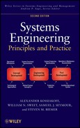
The principles of modular partitioning are illustrated in Figure 11.10. The upper patterns show the elements of “binding,” also referred to as “cohesion,” which measures the mutual relation of items within software modules (represented by boxes with the names of colors). It is desirable for binding to be “tight”—all closely related items should be grouped together in a single functional area. Conversely, unrelated and/or potentially incompatible items should be located in separate areas.

Figure 11.10. Principles of modular partitioning.
The lower two diagrams illustrate the elements of “coupling,” which measures the interactions between the contents of different modules (boxes). With tight coupling as illustrated at the left, any change within a module will likely dictate changes in each of the other two modules. Conversely, with “loose” coupling, interactions between the modules are minimized. The ideal arrangement, usually only partially achievable, is illustrated in the right-hand diagram, where interactions between modules are kept simple and data flows are unidirectional. This subject is discussed further below as it relates to different design methodologies.
Architecture Modeling.
As noted in Chapter 10, models are an indispensable tool of systems engineering for making complex structures and relationships understandable to analysts and designers. This is especially true in software-dominated systems where the abstract nature of the medium can make its form and function virtually incomprehensible.
The two main methodologies used to model software systems are called “structured analysis and design” and “object-oriented analysis and design (OOAD).” The former is organized around functional units called procedures and functions. It is based on a hierarchical organization and uses decomposition to handle complexity. Generally, structured analysis is considered a top-down methodology.
OOAD is organized around units called “objects,” which represent entities and encapsulate data with its associated functions. Its roots are in software engineering and it focuses on information modeling, using classes to handle complexity. Generally, OOAD can be considered a bottom-up methodology.
Structured Analysis and Design
Structured analysis uses four general types of models: the functional flow block diagram (FFBD), the data flow diagram (DFD), the entity relationship diagram (ERD), and the state transition diagram (STD).
FFBD.
The FFBD comes in a variety of forms. We introduced one of those varieties, the functional block diagram, in Chapter 8 (see Fig. 8.4). The FFBD is similar, except that rather than depicting functional interfaces like the block diagram, connections (represented by arrows) represent flow of control. Since the FFBD incorporates sequencing (something that neither the functional block diagram (FBD) nor the integrated definition 0 (IEDF0) formats do), logical breaking points are depicted by summing gates. These constructs enable the depiction of process-oriented concepts. Almost any process can be modeled using the FFBD. Figure 11.11 is an example of an FFBD.

Figure 11.11. Functional flow block diagram example.
As with all functional diagrams, each function within the hierarchy can be decomposed into subfunctions, and a corresponding diagram can be developed at each level. Functional diagrams are the standard method within structured analysis to depict a system’s behavior and functionality.
DFD.
This diagram consists primarily of a set of “bubbles” (circles or ellipses) representing functional units, connected by lines annotated with the names of data flowing between the units. Data stores are represented by a pair of parallel lines and external entities are shown as rectangles. Figure 11.12 shows a DFD for the checkout function of a small public library system.

Figure 11.12. Data flow diagram: library checkout.
A system is normally represented by DFDs at several levels, starting with a context diagram in which there is only one bubble, the system, surrounded by external entity rectangles (see Fig. 3.2). Successive levels break down each of the bubbles at the upper levels into subsidiary data flows. To systems engineers, a software DFD is similar to the functional flow diagram except for the absence of control flow.
ERD.
The ERD model defines the relationships among data objects. In its basic form, the entities are shown as rectangles and are connected by lines representing the relationship between them (shown inside a diamond). In addition to this basic ERD notation, the model can be used to represent hierarchical relationships and types of associations among objects. These models are extensively used in database design.
STD.
An STD models how the system behaves in response to external events. An STD shows the different states that the system passes through, the events that cause it to transition from one state to another, and the actions taken to effect the state transition.
Data Dictionary.
In addition to the above diagrams, an important modeling tool is an organized collection of the names and characteristics of all data, function, and control elements used in the system models. This is called the “data dictionary” and is a necessary ingredient in understanding the meaning of the diagrammatic representations. It is analogous to a hardware part and interface listing of sets of data and procedure declarations, followed by the definition of a number of procedures that operate on the data. It is not difficult to trace the functional relationships, evidenced by function/procedure calls, and thereby to construct a “function call tree” tracing the flow of functions throughout the program.
OOAD
As discussed in Chapter 8, OOAD takes a quite different approach to software architecting. It defines a program entity “class,” which encapsulates data and functions that operate on them, producing more self-contained, robust, and inherently more reusable program building blocks. Classes also have the property of “inheritance” to enable “child” classes to use all or some of the characteristics of their “parent” class with a resultant reduction of redundancy. An object is defined as an instance of a class.
The boundary between the steps of analysis and design in object-oriented (OO) methodology is not precisely defined by the practitioners but generally is where the process of understanding and experimentation changes to one of synthesizing the architectural form of the system. This step also involves some experimentation, but its objective is to produce a complete specification of the software required to meet the system requirements.
The construction of the system architecture in OO methodology consists of arranging related classes into groups—called subsystems or packages—and of defining all of the relations/responsibilities within and among the groups.
OO methodology has been especially effective in many modern information systems that are largely transactional. In such programs as inventory management, financial management, airline reservation systems, and many others, the process is largely the manipulation of objects, physical or numerical. OO methods are not as well suited for primarily algorithmic and computational programs.
Modeling and Functional Decomposition.
Object-oriented design (OOD) also has the advantage of using a precisely defined and comprehensive modeling language—the Unified Modeling Language (UML). This provides a powerful tool for all stages of program development. The characteristics of UML are described in Chapter 8.
A shortcoming of the OO methodology as commonly practiced is that it does not follow a basic systems engineering principle—that of managing complexity by partitioning the system into a hierarchy of loosely coupled subsystems and components. This is accomplished by the systems engineering step of functional decomposition and allocation. By focusing on objects (things) rather than functions, OOD tends to build programs from the bottom-up rather than the top-down approach inherent in the systems engineering method.
OOD does have a structural element, the use case, which is basically a functional entity. As described above, use cases connect the system’s external interfaces (actors) with internal objects. The application of use cases to design the upper levels of the system architecture and introducing objects at lower levels may facilitate the application of systems engineering principles to software system design. This approach is described in Rosenberg’s book, Use Case Driven Object Modeling with UML.
Strengths of UML.
The UML language combines the best ideas of the principal methodologists in the field of OOAD. It is the only standardized, well-supported, and widely used software modeling methodology. It therefore serves as a high-level form of communicating software architectural information within and among organizations and individuals engaged in a development program.
Moreover, UML has been applied successfully in software-intensive systems projects. Portions of UML are also used regularly in systems engineering to assist in communicating concepts and in bridging the language gaps between engineers and users (e.g., use case diagrams) and between software and hardware engineers (e.g., communications diagrams).
A major strength of UML is the existence of commercial tools that support the construction and use of its repertoire of diagrams. In the process, these tools store all the information contained in the diagrams, including names, messages, relationships, attributes, methods (functions), and so on, as well as additional descriptive information. The result is an organized database, which is automatically checked for completeness, consistency, and redundancy. In addition, many of the tools have the property of converting a set of diagrams into C++ or Java source code down to procedure headers. Many also provide a limited degree of reverse engineering—converting source code into one or several top-level UML diagrams. These capabilities can save a great deal of time in the design process.
Other Methodologies
The growing importance of software-dominated systems, and their inherent complexity and abstractness, has engendered a number of variants of structured and OO methodologies. Two of the more noteworthy ones are briefly discussed below.
Robustness Analysis.
This is an extension of OO methodology that serves as a link between OO analysis (what) and design (how). It classifies objects into three types:
- 1. boundary objects, which link external objects (actors) with the system;
- 2. entity objects, which embody the principal objects that contain data and perform services (functions); and
- 3. control objects, which direct the interaction among boundary and entity objects.
Robustness analysis creates a robustness diagram for each UML use case, in which the objects involved in the processing of the use case are classified as boundary and entity objects and are linked by control objects defined for the purpose. An example of a robustness diagram for the checkout use case for an automated library is shown in Figure 11.13. It is seen to resemble a functional flow diagram and to be easily understandable.

Figure 11.13. Robustness diagram: library checkout.
In the process of preliminary design, the robustness diagram is transformed into class, sequence, and other standard UML diagrams. Control objects may remain as controller types, or their functionality may be absorbed into methods of the other objects. To a systems engineer, robustness analysis serves as an excellent introduction to OOAD.
Function-Class Decomposition (FCD).
This methodology, referred to as FCD, is a hybrid method that combines structured analysis with OO methodology. It is aimed at the top-down decomposition of complex systems into a hierarchy of functional subsystems and components, while at the same time identifying objects associated with each unit.
As previously noted, conventional OO methodology tends to design a system from the bottom-up and has little guidance on how to group objects into packages. It is said to lead to a “flat” modular organization. The FCD method seeks to provide a top-down approach to system partitioning by using functional decomposition to define a hierarchical architecture into which objects are integrated. In so doing, it introduces the important systems engineering principle of functional decomposition and allocation into OO software system design.
FCD uses an iterative approach to partition successively lower levels of the system while at the same time also adding such objects as turn out to be needed for the lower-level functions. UML class diagrams are introduced after the first several levels are decomposed. The developers of the FCD method have demonstrated its successful use on a number of large system developments.
11.5 SOFTWARE ENGINEERING DEVELOPMENT: CODING AND UNIT TEST
The process of software engineering development consists of implementing the architectural design of system components, developed in the concept development stage, into an operational software that can control a processor to perform the desired system functions. The principal steps in this process and their systems engineering content are outlined below.
Program Structure
Software has been seen to be embodied in units called computer programs, each consisting of a set of instructions.
Program Building Blocks.
A computer program may be considered to consist of several types of subdivisions or building blocks. In descending order of size, the subdivisions of a computer program and their common names are as follows:
- 1. A “module” or “package” constitutes a major subdivision of the overall program, performing one or more program activities. A medium to large program will typically consist of from several to tens or hundreds of modules.
- 2. In OO programs, a class is a unit composed of a set of “attributes” (data elements) combined with a set of associated “methods” or “services” (functions). An object is an instance of a class.
- 3. A function is a set of instructions that performs operations on data and controls the processing flow among related functions. A “utility” or “library function” is a commonly used transform (e.g., trigonometric function) that is supplied with an operating system.
- 4. A “control structure” is a set of instructions that controls the order in which they are executed. The four types of control structures are the following:
- (a) Sequence: a series of instructions;
- (b) Conditional Branch: if (condition) then (operation 1), else (operation 2);
- (c) Loop: do while (condition) or do until (condition); and
- (d) Multiple Branch: case (key 1): (operation 1) … (key n) (operation n).
- 5. An “instruction” is a “declarative” or “executable” order to the computer, composed of language key words, symbols, and names of data and functions.
- 6. A language key word, symbol, or name of a data element or function.
Finally, a “data structure” is a definition of a composite combination of related data elements, such as a “record,” “array,” or “linked list.”
As noted previously, software has no commonly occurring building blocks comparable to standard hardware parts and subcomponents such as pumps, motors, digital memory chips, cabinets, and a host of others that simplify designing and building production hardware. With few exceptions, software components are custom designed and built.
Program Design Language (PDL).
A useful method for representing software designs produced by the conventional structured analysis and design methodology is PDL, sometimes called “structured English.” This consists of high-level instructions formatted with control structures like an actual computer program, but consists of textual statements rather than programming language key words and phrases. PDL produces a program listing that can be readily understood by any software engineer and can be translated more or less directly into executable source codes.
OOD Representation.
It was seen that OOD produces a set of diagrams and descriptive material, including defined objects that constitute intermediate program building blocks. Through the use of a UML support tool, the design information can be automatically converted into the architecture of the computer program.
Programming Languages
The choice of programming language is one of the major decisions in software design. It depends critically on the type of system—for example, whether software-embedded, software-intensive, or data-intensive computing, whether military or commercial, or whether real-time or interactive. While it is often constrained by the programming talents of the software designers, the nature of the application should have priority. A language may impact the maintainability, portability, readability, and a variety of other characteristics of a software product.
Except for very special applications, computer programs are written in a high-level language, where individual instructions typically perform a number of elementary computer operations. Table 11.5 lists a sample of past and current computer languages, their structural constituents, primary usage, and general description.
TABLE 11.5. Commonly Used Computer Languages

Fourth-Generation Language (4GL) and Special-Purpose Language.
4GLs are typically proprietary languages that provide higher-level methods to accomplish a problem solution in a specific domain. These 4GLs are usually coupled with a database system and are related to use of the structured query language (SQL). A key feature of 4GL tools is to bring the programming language environment as close to the natural language of the problem domain as possible and to provide interactive tools to create solutions. For example, the creation of a user input form on a workstation is carried out interactively with the programmer. The programmer enters the labels and identifies allowable entry values and any restrictions, and then the “screen” becomes part of the application. 4GLs can speed up the development time for specific applications but are generally not portable across products from different vendors.
There are many specialty areas where very efficient high-level languages have been developed. Such languages usually take on the jargon and constructs of the area they are intended to serve. The intent of these special-purpose languages is to mimic the problem domain where possible, and to decrease development time while increasing reliability. In many cases, the special-purpose nature of such languages may limit performance for the sake of ease of use and development. When undertaking custom software development, the systems engineer should explore the availability and utility of languages in a required specialty area. Table 11.6 lists a number of special-purpose languages that have been developed for specific application domains, such as expert systems and Internet formatting.
TABLE 11.6. Some Special-Purpose Computer Languages

Programming Support Tools
To support the effort of developing computer programs to implement software system design, a set of programming support tools and training in their effective use is essential. It is useful for the systems engineer and program manager to be knowledgeable about their uses and capabilities.
Editors.
Editors provide programmers with the means to enter and change source code and documentation. Editors enhance the entry of programming data for specific languages. Some editors can be tailored to help enforce programming style guides.
Debuggers.
Debuggers are programs that allow an application to be run in a controlled manner for testing and debugging purposes. There are two major types of debuggers: symbolic and numeric. The symbolic debugger allows the user to reference variable names and parameters in the language of the source code. A numeric debugger works at the assembly or machine code level. The computer instructions written in a programming language is called “source code.” To convert the source code produced by the programmers into executable code, several additional tools are required.
Compilers.
A compiler converts the source language into an intermediate format (often called object code) that is compatible for use by the hardware. In this process, the compiler detects syntax errors, omissions of data declarations, and many other programming errors, and identifies the offending statements.
A compiler is specific to the source language and usually to the data processor. Compilers for a given language may not be compatible with each other. It is important to know what standards govern the compiler that will be used and to be aware of any issues associated with code portability. Some compilers come with their own programming development environment that can increase programmer productivity and simplify the program documentation process.
Linkers and Loaders.
A linker links several object code modules and libraries together to form a cohesive executable program. If there is a mixed language application (C and Java are common), the combination of a compiler and linker that works on multiple languages is required. Tools that help manage the linking of complex applications are essential in the management and control of software development. A loader converts linked object code into an executable module that will run in the designated environment. It is often combined with the linker.
Software Prototyping
The section on the software system life cycle described several models that used the prototyping approach, either once or recursively. The objective of software prototyping is the same as it is in hardware systems, where it is used to reduce risks by constructing and testing immature subsystems or components. In software systems, prototyping is generally used even more frequently for three reasons: (1) requirements are poorly defined; (2) the functionality is unproven; and (3) building the prototype does not require bending metal, only writing code.
Conventionally, a prototype is often taken to mean a test model that is to be discarded after being used. In practice, the system prototype often becomes the first step in an evolutionary development process. This strategy has the advantage of preserving the design features of the prototype after they have been improved as a result of user feedback, as well as building upon the initial programming effort. However, it requires that the prototype programs be engineered using a disciplined and well-planned and documented process. This places a limit on how fast the process can be. The choice of strategy must obviously be based on the particular requirements and circumstances of the project. Table 11.7 lists the typical characteristics of exploratory prototypes, which are meant to be discarded, and of evolutionary prototypes, which are meant to be built upon.
TABLE 11.7. Characteristics of Prototypes
| Aspect | Exploratory | Evolutionary |
| Objective |
|
|
| Nature of product |
|
|
| Environment | Virtual | Operational |
| Configuration management | Informal | Formal |
| Testing | Partial | Rigorous |
| Ultimate use | Disposable | A foundation for further builds |
The success of a prototyping effort is critically dependent on the realism and fidelity of the test environment. If the test setup is not sufficiently realistic and complete, the prototype tests are likely to be inadequate to validate the design approach and sometimes can be actually misleading. The design of the test should receive a comparable degree of expert attention as the prototype design itself. As in hardware systems, this is a key area for systems engineering oversight.
Software Product Design
In typical hardware system developments, product design consists of the transformation of development prototype hardware components, which might be called “breadboards,” into reliable, maintainable, and producible units. In this process, the functional performance is preserved, while the physical embodiments may be changed quite radically. Much of this work is carried out by engineers particularly skilled in the problems of production, environmental packaging, materials, and their fabrication methods, with the objective that the final product can be produced efficiently and reliably.
In the software elements of the system, the product design process is very different. There is no “production” process in software. However, other aspects of a production article are still present. Maintainability continues to be a critical characteristic due to the numerous interfaces inherent within software. Repair by replacement of a failed component—a standby in hardware—does not work in software. An effective user interface is another crucial characteristic of operational software that is often not achieved in the initial version of the system.
Thus, considerable effort is usually required to make a working computer program into a software product usable by others. Fred Brooks has postulated this effort to be three times the effort required to develop a working program. However, there is no professional group in software engineering comparable to the hardware production and packaging engineer. Instead, the “productionization” must be incorporated into the software by the same designers responsible for its basic functionality. Such breadth of expertise is often not present in the average software designer, with the result that maintainability of software products is frequently less than satisfactory.
Computer User Interfaces.
As noted previously, a critical part of engineering operational software systems is the design of the user interface. A computer interface should display information in a form giving the user a clear and well-organized picture of the system status so as to assist the decision process effectively and to provide simple and rapid modes of control. The selection of the appropriate interface mode, display format, interactive logic, and related factors most often requires prototype design and testing with representative users.
The most common control modes offered by computer interfaces are menu interactions, command languages, and object manipulation. A summary of some comparative characteristics of these is given in Table 11.8.
TABLE 11.8. Comparison of Computer Interface Modes

The most rapidly growing computer interface mode is that of object manipulation, the objects being usually referred to as “icons.” In addition to the characteristics listed in Table 11.8, graphical presentations of information can often present relationships and can convey meaning better than text. They enable the user to visualize complex information and form inferences that can lead to faster and more error-free decisions than can be achieved by other methods. GUIs are most commonly seen in PC operating systems such as Macintosh OS and Microsoft Windows. The power of the World Wide Web owes a great deal to its GUI formats.
To the systems engineer, GUIs offer both opportunities and challenges. The opportunities are in the virtually infinite possibilities of presenting information to the user in a highly enlightening and intuitive form. The challenges come from the same source, namely, the sheer number of choices that tempt the designer to continue to optimize, unrestrained by an inherent limit. Since GUIs involve a complex software design, there is a risk of cost and schedule impact if the systems engineer is not alert to this hazard.
Advanced Modes.
In designing user interfaces for computer-controlled systems, the rapidly advancing technology in this area makes it necessary to consider less conventional modes that offer special advantages. Three examples are briefly described below:
- 1. Voice Control. Spoken commands processed by speech recognition software provide a form of rapid and easy input that leaves the hands free for other actions. Currently, reliable operation is somewhat limited to carefully enunciated words selected from a fixed vocabulary. Capabilities to understand sentences are gradually being evolved.
- 2. Visual Interaction. Computer graphics are being used to aid decision makers by generating displays modeling the results of possible actions, enabling “what-if” simulations in real time. Visual interactive simulation (VIS) is an advanced form of visual interactive modeling (VIM).
- 3. Virtual Reality. A form of 3-D interface in which the user wears stereo goggles and a headset. Head movements generate a simulated motion of the image corresponding to what the eyes would see in the virtual scene. Such displays are used for a growing variety of tasks, such as design of complex structures and pilot training. They are used in battlefield situations and games.
Unit Testing
The engineering design phase of system development begins with the engineering of the individual system components whose functional design has been defined and the technical approach validated in the previous phase. Before the resulting engineered component is ready to be integrated with the other system components, its performance and compatibility must be tested to ensure that they comply with requirements. In software development, this test phase is called “unit testing” and is focused on each individual software component.
Unit tests are generally performed as “white box” tests, namely, those based on the known configuration of the component. Such tests deliberately exercise the critical parts of the design, such as complex control structures, external and internal interfaces, timing or synchronization constraints, and so on.
A compensating characteristic of software for the added testing problems is that the test equipment itself is almost wholly software and can usually be designed and built correspondingly quickly. However, the effort of test design must be as carefully planned and executed as is the system design.
Unit tests for a given component or major module consist usually of a series of test cases, each designed to test a control path, a data structure, a complex algorithm, a timing constraint, a critical interface, or some combination of these. Test cases should be designed to test each function that the unit is required to perform. Since there are typically too many paths to test them all, the selection of test cases requires systems engineering judgment.
Errors uncovered in unit testing should be documented and decisions made as to when and how they should be corrected. Any corrective changes must be carefully considered before deciding which previous test cases should be repeated.
11.6 SOFTWARE INTEGRATION AND TEST
The subject of system integration and evaluation is discussed in detail in Chapter 13, and the general techniques and strategies apply equally to the software components of software-embedded systems and to the software-intensive systems themselves. The discussion makes clear that this aspect of a system’s development process is critically important, that it must be carefully planned, expertly executed, and rigorously analyzed, and that the magnitude of the effort required is a large fraction of the entire development effort.
At the system level, the test objectives and strategies of software-dominated systems are similar to those described in Chapter 13. At the software component level, it is necessary to use testing approaches more nearly designed to test software units. The balance of this chapter is devoted to methods of integration and testing complex software programs and software-intensive systems.
The objectives of testing hardware components and subsystems are many—from reducing technical and programmatic risks to verifying specifications. Additional objectives related to politics, marketing, and communications are also part of a system test program. At the lower element level, however, the objectives of testing hardware and software converge.
For software, the objective of testing generally falls into a single category: verification or validation of the software. Moreover, the general method to accomplish this objective is to discover and identify all instances where the program fails to perform its designated function. These range all the way from a case where it fails to meet an essential requirement to where a coding error causes it to crash. Contrary to popular belief, the most valuable test is one that finds a hitherto undiscovered error, rather than one in which the program happens to produce the expected result. Because of the large variety of input scenarios characteristic of the environment of a complex system, the latter result may simply mean that the program happens to handle the particular conditions imposed in that test.
Verification and Validation
Although the terms verification and validation are not for software only, they apply equally to hardware and systems—they are often used more within a software context than any other. Verification is simply the process of determining whether the software implements the functionality and features correctly and accurately. These functions and features are usually found in a software specifications description. In other words, verification determines whether we implemented the product right.
Validation, in contrast, is the process of determining whether the software satisfies the users’ or customers’ needs. In other words, validation determines whether we implemented the right product.
Testing is typically a primary method used to perform verification and validation, though not the only method. However, a robust test program can satisfy a large portion of both evaluation types.
Differences in Testing Software
While the general objectives of testing software may be the same as testing hardware system elements, the basic differences between hardware and software described at the beginning of this chapter make software testing techniques and strategies considerably different.
Test Paths.
The unconstrained use of control structures (branches, loops, and switches) may create a multitude of possible logical paths through even a relatively small program. This makes it impractical to test all possible paths and forces the choice of a finite number of cases.
Interfaces.
The typically large number of interfaces between software modules, and their depth and limited visibility, makes it difficult to locate strategic test points and to identify the exact sources of discrepancies encountered during testing.
Abstraction.
The design descriptions of software are more abstract and are less intuitively understandable than hardware design documentation. This complicates test planning.
Changes.
The apparent ease of making changes in software requires correspondingly more frequent retesting. Local changes often require repetition of system-level tests.
Failure Modes.
The catastrophic nature of many software errors has two critical consequences. One is the severity of the impact on system operation. The other is that prompt diagnosing of the source of the failure is often frustrated by the inoperability of the system.
Integration Testing
Integration testing is performed on a partially assembled system as system components are progressively linked together. The integration of a complex system is described in Chapter 13 to be a process that must be carefully planned and systematically executed. This is no less true with software systems. The principles and general methods discussed in that chapter apply equally.
Regression Testing
In an integration test sequence, the addition of each component creates new interactions among previously integrated components, which may change their behavior and invalidate the results of earlier successful tests. Regression testing is the process of repeating a selected fraction of such tests to ensure the discovery of newly created discrepancies. The more numerous, complex, and less visible interactions typical of software make it necessary to resort to regression testing more often than for primarily hardware systems.
A problem with regression testing is that unless it is used judiciously, the number of tests can grow beyond practical bounds. For this reason, the test strategy should include careful selectivity of the test cases to be repeated. A balance must be struck between insufficient and excessive rigor to achieve a usable yet affordable product; a systems engineering approach to planning and carrying out integration testing is required.
Validation Testing
Validation testing is intended to determine whether or not a system or a major subsystem performs the functions required to satisfy the operational objectives of the system. Validation testing consists of a series of test scenarios, which collectively exercise the critical system capabilities.
The planning of validation testing and design of test cases also demands a systems engineering approach. The same is true of the analysis of test results, which requires a thorough knowledge of system requirements and of the impact of any significant deviations from nominally required performance. At this stage of system development, decisions on how to handle test discrepancies are critically important. The choice between embarking on a corrective change or seeking a deviation requires an intimate knowledge of the impact of the decision on program cost, schedule, and system performance. Often the best course of action is to investigate the operation of the test equipment, which is itself occasionally at fault, and to repeat the test under more controlled conditions.
Black Box Testing.
The section on unit testing described white box testing as addressing the known design features of the component. Validation and other system-level tests consider the system under test as an input-to-output transfer function, without any assumption of its internal workings. As such, black box testing is complementary to white box testing and is likely to uncover interface errors, incorrect functions, initialization errors, as well as critical performance errors.
Alpha and Beta Testing.
For software products built for many users, as in the case of much commercial software, most producers have a number of potential customers operate the software before releasing the product for distribution. Alpha testing is typically conducted in a controlled environment at the developer’s site, often by employees of a customer. The developer records errors and other problems. Beta testing is conducted at a customer’s site without the developer’s presence. The customer records the perceived errors and operating problems and reports these to the developer. In both cases, the advantage to the customer is the opportunity to become acquainted with an advanced new product. The developer gains by avoiding the risk of fielding a product containing user deficiencies that would significantly curtail the product’s marketability.
11.7 SOFTWARE ENGINEERING MANAGEMENT
The basic elements of managing the development of complex systems were discussed in Chapter 5, and specific aspects in Chapters 6–10. This section deals with some aspects of the management of software-dominated systems that are particularly influenced by the distinguishing character of software, of which systems engineers should be cognizant.
Computer Tools for Software Engineering
Software support tools are software systems that assist the development and maintenance of software programs. In any major software development effort, the availability and quality of the support tools may spell the difference between success and failure. Support tools are used in all aspects of the product life cycle and are becoming more widely available in the commercial marketplace. For these reasons, and the fact that tools for a major software development project require very significant investment, the subject is a proper concern of systems engineers and project managers.
The more specific subject of programming support tools was described briefly in Section 11.5. The paragraphs below discuss the subject of integrated computer-aided software engineering (CASE) tools and some of their typical applications.
CASE.
CASE is a collection of tools that are designed to standardize as much of the software development process as possible. Modern CASE tools revolve around graphics-oriented diagramming tools that let the designer define the structure, program and data flow, modules or units, and other aspects of an intended software application. By the use of well-defined symbology, these tools provide the basis for the requirements analysis and design phases of the development cycle.
Requirements Management Tools.
The derivation, analysis, quantification, revision, tracing, verification, validation, and documentation of operational, functional, performance, and compatibility system requirements have been seen to extend throughout the system life cycle. For a complex system development, it is a critical and exacting task that involves operational, contractual, as well as technical issues. Several computer-based tools are commercially available that assist in creating an organized database and provide automatic consistency checks, traceability, report preparation, and other valuable services.
Software Metrics Tools.
Several commercial tools and tool sets are available to produce automatically measures of various technical characteristics of computer programs, relating to their semantic structure and complexity. (See later section on metrics.)
Integrated Development Support Tools.
Several tools have become available that provide a set of compatible integrated support functions, and, in some cases, the capability of importing and exporting data from and to complementary tools from other manufacturers. For example, some tools integrate project management, UML diagramming, requirements analysis, and metrics acquisition capabilities. Such tools simplify the problem of maintaining information consistency among the related domains of software development.
Software Configuration Management (CM).
CM in system development was discussed at some length in Chapter 10. Its importance increases with system complexity and criticality. In software systems, strict CM is the most critical activity during and after the engineering development stage. Some of the reasons for this may be inferred from the section on the differences between hardware and software:
- 1. Software’s abstractness and lack of well-defined components makes it difficult to understand.
- 2. Software has more interfaces; their penetration is deeper and hence is difficult to trace.
- 3. Any change may propagate deep into the system.
- 4. Any change may require retesting of the total system.
- 5. When a software system fails, it often breaks down abruptly.
- 6. The flexibility of software renders making a software change deceptively easy.
Capability Maturity Model Integration (CMMI)
The abstract nature of software, and its lack of inherent limits on functionality, complexity, or size, makes software development projects considerably more difficult to manage than hardware projects of comparable scope.
Organizations whose business is to produce software-intensive systems or components and to meet firm schedules and costs have often failed to meet their goals because their management practices were not suited to the special needs of software. To help such organizations produce successful products, the Carnegie Mellon University Software Engineering Institute (SEI), operating under government sponsorship, devised a model representing the capabilities that an organization should have to reach a given level of “maturity.” This is called a capability maturity model (CMM). A maturity model defines a set of maturity levels and prescribes a set of key process areas that characterize each level. This model provides a means for assessing a given organization’s capability maturity level through a defined set of measurements. CMM has been accepted as a standard of industry. It is related to but not equivalent to the International Standard ISO 9000 for software.
Software and systems engineering had separate maturity models until the SEI published the first integrated CMM, combining several previous models into a single, integrated model known as CMMI. Today, CCMI addresses three specific areas of interest: (1) product and service development; (2) service establishment, management, and delivery; and (3) product and service acquisition. As of this writing, CMMI, Version 1.2 is the latest version of the model.
At its core, CMMI is a process improvement methodology. Understanding the current maturity of an organization’s processes and identifying the objective maturity level for the future are keys concepts behind the model. Therefore, one aspect of CMMI is the formal definition of maturity levels. These apply to organizations, not projects, although as projects grow in size and complexity, the lines of demarcation between an organization and a project can become blurred.
Capability Maturity Levels.
The CMM defines six capability and five maturity levels as summarized in Tables 11.9 and 11.10. The CMMI process is fully institutionalized. Key performance areas (KPAs) are defined for each level and are used in determining an organization’s maturity level. Each KPA is further defined by a set of goals and key practices that address these goals. SEI also defines key indicators that are designed to determine whether or not the KPA goals have been achieved. These are used in CMM assessments of an organization’s capability maturity level.
TABLE 11.9. Capability Levels
| Capability level 0: incomplete |
| An “incomplete process” is a process that either is not performed or partially performed. One or more of the specific goals of the process area are not satisfied, and no generic goals exist for this level since there is no reason to institutionalize a partially performed process. |
| Capability level 1: performed |
| A performed process is a process that satisfies the specific goals of the process area. It supports and enables the work needed to produce work products. |
| Capability level 2: managed |
| A managed process is a performed (capability level 1) process that has the basic infrastructure in place to support the process. It is planned and executed in accordance with police; employs skilled people who have adequate resources to produce controlled outputs; involves relevant stake holders; is monitored, controlled, and reviewed; and is evaluated for adherence to its process description. |
| Capability level 3: defined |
| A defined process is a managed (capability level 2) process that is tailored from the organization’s set of standard processes according to the organization’s tailoring guidelines and contributes work products, measures, and other process improvement information to the organizational process assets. |
| Capability level 4: quantitatively managed |
| A quantitatively managed process is a defined (capability level) process that is controlled using statistical and other quantitative techniques. Quantitative objectives for quality and process performance are established and used as criteria in managing the process. Quality and process performance is understood in statistical terms and is managed throughout the life of the process. |
| Capability level 5: optimizing |
| An optimizing process is a quantitatively managed (capability level 4) process that is improved based on an understanding of the common causes of variation inherent in the process. The focus of an optimizing process is on continually improving the range of process performance through both incremental and innovative improvements. |
TABLE 11.10. Maturity Levels
| Maturity level 1: initial |
| Processes are usually ad hoc and chaotic. |
| Maturity level 2: managed |
| The projects of the organization have ensured that processes are planned and executed in accordance with policy; the projects employ skilled people who have adequate resources to produce controlled outputs; involve relevant stakeholders; are monitored, controlled, and reviewed; and are evaluated for adherence to their process descriptions. |
| Maturity level 3: defined |
| Processes are well characterized and understood, and are described in standards, procedures, tools, and methods. The organization’s set of standard processes, is established and improved over time. These standard processes are used to establish consistency across the organization. Projects establish their defined processes by tailoring the organization’s set of standard processes according to tailoring guidelines. |
| Maturity level 4: quantitatively managed |
| The organization and projects establish quantitative objectives for quality and process performance and use them as criteria in managing processes. Quantitative objectives are based on the needs of the customer, end uses, organization, and process implementers. Quality and process performance is understood in statistical terms and is managed through cut the life of the processes. |
| Maturity level 5: optimizing |
| An organization continually improves its processes based on a quantitative understanding of the common causes of variation inherent in processes. |
CMMI is widely used by industry, especially by large system and software development organizations. The U.S. DoD prescribes a demonstration of CMMI Level 3 capability for major system acquisitions. However, the investment necessary to achieve CMMI certification is considerable, and it is generally estimated that going from level 1 to level 2 or from level 2 to level 3 requires from 1 to 2 years.
Systems Engineering Implications.
Examination of the KPAs reveals that they address a combination of project management, systems engineering, and process improvement issues. At level 2, the KPAs addressing requirements management and CM are clearly systems engineering responsibilities, while project planning, project tracking and oversight, and subcontract management are mainly project management functions. At level 3, software product engineering, intergroup coordination, and peer reviews are of direct concern to systems engineers. At higher levels, the focus is largely on process improvement based on quantitative measurements of process results.
Software Metrics
Metrics are quantitative measures used to assess progress, uncover problems, and provide a basis for improving a process or product. Software metrics can be classified as project metrics, process metrics, or technical metrics.
Project Metrics.
Software project metrics are concerned with measures of the success of project management—stability of requirements, quality of project planning, adherence to project schedules, extent of task descriptions, quality of project reviews, and so on. These are basically the same as would be used on any comparable project to track management practices. A reason for greater attention to project metrics on a software development is the traditionally more difficult task of reliable planning and estimating new software tasks. Project metrics should be tailored to the formality, size, and other special characteristics of the project.
Process Metrics.
Software process metrics are fundamental to the practice of establishing process standards as described in the previous section on software capability maturity assessment. Such standards identify a set of process areas that need to be addressed. They do not generally prescribe how they should be handled but require that appropriate practices be defined, documented, and tracked.
Technical Metrics.
Technical software metrics are focused largely on assessing the quality of the software product rather than on management or process. In that sense, they are an aid to design by identifying sections of software that are exceptionally convoluted, insufficiently modularized, difficult to test, inadequately commented, or otherwise less than of high quality. Such measures are useful for directly improving the product, and for refining design and programming practices that contributed to the deficiencies. There are numerous commercial tools that are designed to track technical software metrics.
Management of Metrics.
Software metrics can be useful in developing good practices and in improving productivity and software quality. However, they can also be misused with negative results for the projects and the software staff. It is important to observe a number of principles in the management of metrics:
- 1. The purpose of each metric must be clearly understood by all concerned to be beneficial and worth the effort to collect and analyze.
- 2. The metrics collected on a given project should be appropriate to its character and criticality.
- 3. The results of metrics collection should be used primarily by the project to increase its probability of success.
- 4. The results should never be used to threaten or appraise individuals or teams.
- 5. There should be a transition period for the introduction of new metrics before the data collected are used.
Future Outlook
The continuing growth of information systems is exerting severe pressure to improve software technology in order to keep pace with rising demands and to minimize risks of major software project failures, which have been all too frequent in recent years. Furthermore, the unreliability of much commercial software has frustrated many computer users. Below are some trends that have the potential to meet some of the above needs.
Process Improvement.
The establishment and widespread adoption of software process standards, such as CMMI, have significantly strengthened the discipline used in software design. They have introduced engineering practices and management oversight into a culture derived from science and art. For large, well-defined projects, these approaches, which have been found to reduce failure rates, vary significantly. For smaller projects having loosely defined requirements, agile methods have attracted many adherents.
Programming Environment.
Computer-aided programming environments, such as that for Visual Basic, are likely to continue to improve, providing better automatic error checking, program visualization, database support, and other features designed to make programming faster and less prone to error. Integration of syntax checking, debugging, and other programming support functions into the environment, along with more powerful user interfaces, is likely to continue to improve productivity and accuracy.
Integrated CASE Tools.
Requirements and CM tools are being integrated with modeling and other functions to facilitate the development, upgrading, and maintenance of large software programs. The integration of these tools enables the traceability of program modules to requirements and the management of the massive number of data elements present in complex systems capabilities. While the development of such tools is expensive, their growth and consequent increases in productivity are likely to continue, especially if more emphasis is placed on reducing the time and cost of becoming proficient in their use.
Software Components.
Reuse of software components has long been a major goal, but its effective realization has been the exception rather than the rule. One such exception has been the availability of commercial GUI components, supporting features such as windowing and pull-down menus. With the proliferation of automated transactional systems (financial, travel, inventory, etc.), it is likely that numerous other standard components will be identified and made commercially available. The gains in development cost and reliability in automated transactional systems are potentially very large.
Design Patterns.
A different approach to reusable components has been the development of design patterns. A seminal work on this subject by Gamma et al. defines 23 basic patterns of OO functions and describes an example of each. The patterns are subdivided into three classes: creational patterns that build various types of objects, structural patterns that operate on objects, and behavioral patterns that perform specified functions. While this approach appears to hold great promise of creating versatile software building blocks, it has thus far not been adopted by a significant fraction of developers.
Software Systems Engineering.
Perhaps the most significant advance in the development of software-dominated systems would come from the effective application of systems engineering principles and methods to software system design and engineering. Despite the many differences between the nature of software and hardware technologies, some avenues to narrowing this gap are being actively explored. The development of the CMMI by SEI, which addresses both systems engineering and software engineering in a common framework, may contribute to a more common outlook. However, real progress in this direction must involve education and extensions of current software methodologies to facilitate modular partitioning, clean interfaces, architectural visibility, and other basic features of well-designed systems. The continuing demand for complex software-dominated systems may accelerate efforts to introduce systems engineering methods into software development.
11.8 SUMMARY
The terms software engineering and software systems engineering are not synonymous, however. The former refers to the development and delivery of software products, stand-alone or embedded. The latter refers to the application of principles to the software engineering discipline. We define software as having three major components: (1) instructions, also referred to as code; (2) data structures; and (3) documentation.
Coping with Complexity and Abstraction
The role of software has changed over the past 20 years—most modern systems are dominated by software. Therefore, software engineering has become a full part of system development.
Nature of Software Development
Software can be categorized as either
- (a) system software, providing services to other software;
- (b) embedded software, providing functions, services, or features within a larger system; or
- (c) application software, providing services as a stand-alone system.
Systems that utilize software can be categorized in one of three ways:
- 1. Software-Embedded Systems are a hybrid combination of hardware and software. Although predominantly hardware, these systems use software to control the action of hardware components. Examples are most vehicles, spacecraft, robotics, and military systems.
- 2. Software-Intensive Systems consist of computers and networks, controlled by software. These systems use software to perform virtually all of the systems’ functionality, including all automated complex information functionality. Examples are financial management, airline reservations, and inventory control.
- 3. Data-Intensive Computing Systems are large-scale computing resources dedicated to executing complex computational tasks. Examples are weather analysis and prediction centers, nuclear effects prediction systems, advanced information decryption systems, and other computationally intensive operations.
Software has intrinsic differences from hardware, including
- near-infinite variability of software structural units
- few commonly occurring software components;
- software is assigned most critical functions;
- interfaces are more numerous, deeper, and less visible; software functionality and size have almost no inherent limits; software is easily changeable;
- simple software changes may require extensive testing; software often fails abruptly, without warning signs; and
- software is abstract and difficult to visualize.
Software Development Life Cycle Models
The life cycles of software-dominated systems are generally similar to the systems engineering life cycle described in Chapter 4. While there are a plethora of life cycle models, we can define four basic types:
- 1. Linear— a sequence of steps, typically with feedback;
- 2. Incremental— a repetition of a sequence of steps to generate incremental capabilities and functionality until the final increment, which incorporates full capabilities;
- 3. Evolutionary— similar to incremental, except early increments are intended to provide functionality for experimentation, analysis, familiarization, and demonstration. Later increments are influenced heavily from experience with early increments.
- 4. Agile— the typical steps for software development are combined in various forms to enable rapid yet robust development.
Software Concept Development: Analysis and Design
Performance requirements for software-embedded systems are developed at the system level and should be verified by software developers.
Performance requirements for software-intensive systems should be established with close interaction with customers/users and may need to be verified by rapid prototyping. They should not unreasonably stress software extensibility.
Software requirements are typically developed using four steps: elicitation from users, customers and stakeholders, analysis and negotiation with customers, documentation, and validation.
Two prevailing methodologies for designing software systems are structured analysis and design and OOAD. Structured analysis focuses on functional architecture, using functional decomposition, and defines program modules as the primary structural units. This methodology proceeds with top-down functional allocation. In contrast, OOAD focuses on “classes” of objects as program units and encapsulates data variables with operations. This methodology uses an iterative rather than a top-down development.
Other methodologies include robustness analysis, which focuses on initial OO architectural design, FCD, and combined structured and OO approaches.
UML supports all phases of OO development. UML provides 13 types of diagrams, presenting different views of the system, and is widely used. UML has been adopted as an industry standard.
Software Engineering Development: Coding and Unit Test
The engineering design phase of software development implements software architectural design and the computer instructions to execute the prescribed functionality. The phase produces computer programs written in a high-level language (source code) and subjects each program unit to a “unit test” before acceptance.
The programming language must be suited to the type of software and compiler availability. It must conform with the design methodology and requires that staff experienced with the language be available.
Prototyping an iterative development comes in two forms: (1) purely exploratory and is to be discarded once its purpose is fulfilled, and (2) evolutionary, and is to be built upon. In the latter case, high quality must be built in from the beginning.
Human–computer interfaces are critical elements in all software-intensive systems. These types of interfaces usually use interactive graphics formats and may include voice activation and other advanced techniques.
Software Integration and Test
Testing software systems involves many more test paths and interfaces than hardware and requires special test points for diagnosing failures and their sources. Testing often requires end-to-end system-level retesting after eliminating a failure.
Alpha and beta testing subject the new system to tests by the customer and expose user problems before wide product distribution.
Software Engineering Management
CM for software-dominated systems is critical in that software is inherently complex and has numerous and deep interfaces. Since software is responsible for controlling some of the most critical system functions, software tends to be subject to frequent changes.
The CMMI establishes six levels of capability and five levels of maturity for an organization. CMMI establishes KPAs for each level and provides a basis for assessing an organization’s overall systems and software engineering capability.
PROBLEMS
- 11.1 With reference to Figure 11.1, list two specific examples of each of the blocks shown in the diagrams. For one case of each block, describe the kind of data that flows along the paths shown by the lines between the blocks.
- 11.2 Look up (if necessary) the principal subcomponents of the data processor (CPU) of a personal computer. Draw a block diagram of the subcomponents and their interconnections. Describe in your own words the functions of each subcomponent.
- 11.3 Extend the examples of the three types of software-dominated systems shown in Table 11.1 by listing two more examples of each type. Briefly indicate why you placed each example into the selected category.
- 11.4 Using the example of an automated supermarket grocery inventory and management system, draw the system context diagram. Assume that the master-pricing database comes from a central office. Neglect special discounts for store card carriers.
- 11.5 For the same example, define the functions performed by the automated grocery system in processing each individual grocery item. Differentiate between those carrying bar codes and those sold by weight.
- 11.6 Draw a functional flow diagram for the processing of a grocery item showing the two alternate branches mentioned in Problem 11.5.
- 11.7 Identify the objects involved in the above automated grocery system and their attributes. Draw an activity diagram corresponding to the processes described in Problem 11.6.
For Problems 11.8–11.12, suppose you have been asked to develop the software for an elevator system for a multistory building. The system will contain three elevators and will have five floors and a basement-level parking garage.
- 11.8 Develop 20–25 functional and performance requirements for this software system. Please perform analysis on your list to ensure your final list is robust, consistent, succinct, nonredundant, and precise.
- 11.9
- (a) Identify 8–12 top-level functions for this software system.
- (b) Draw an FFBD for this system using the functions in (a).
- 11.10
- (a) Identify 8–12 classes for this software system. Each class should have a title, attributes, and operations.
- (b) Draw a class diagram showing the associations between the classes in (a).
- 11.11
- (a) Identify the 8–12 top-level hardware components of the elevator system.
- (b) Identify the interfaces between the software and hardware components of this system in (a). Please construct a table with three columns. In the first column, labeled “hardware component,” identify the component in which the software will need to interface. In the second column, labeled “input/output,” identify whether the interface is an input, an output, or both. In the third column, labeled “what is passed,” identify what is passed between the software and hardware.
- 11.12 Develop an operational test plan for this software system. The test plan should include a purpose, a description of no more than five tests, and a linkage between each test and the requirement(s) that are being tested.
FURTHER READING
G. Booch, J. Rumbaugh, and J. Jacobson. The Unified Modeling Language User Guide. Addison-Wesley, 1999.
F. P. Brooks, Jr. The Mythical Man Month—Essays on Software Engineering. Addison-Wesley, 1995, Chapter 8.
B. Bruegge and A. H. Dutoit. Object-Oriented Software Engineering. Prentice Hall, 2000, Chapters 1–7.
P. DeGrace and L. H. Stahl. Wicked Problems, Righteous Solutions. Yourdon Press, Prentice Hall, 1990, Chapter 3.
A. Denis, B. H. Wixom, and R. M. Roth. Systems Analysis Design, Third Edition. John Wiley & Sons, Inc., 2006, Chapters 4, 6, and 8–10.
G. Eisner. Computer-Aided Systems Engineering. Prentice Hall, 1988, Chapters 8 and 14.
H. Eisner. Essentials of Project and Systems Engineering Management. John Wiley & Sons, Inc., 1997, Chapters 10 and 12.
E. Gamma, R. Helm, R. Johnson, and J. Dlissides. Design Patterns. Addison-Wesley, 1995.
K. E. Kendall and J. E. Kendall. Systems Analysis and Design, Sixth Edition. Prentice Hall, 2005, Chapters 6, 7, 14, and 18.
M. Maier and E. Rechtin. The Art of Systems Architecting. CRC Press, 2009, Chapter 6.
R. S. Pressman. Software Engineering: A Practitioner’s Approach, Sixth Edition. McGraw-Hill, 2005, Chapters 20–24.
E. Rechtin. Systems Architecting: Creating and Building Complex Systems. Prentice Hall, 1991, Chapter 5.
N. B. Reilly. Successful Systems for Engineers and Managers. Van Nostrand Reinhold, 1993, Chapters 13 and 14.
D. Rosenberg. Use Case Driven Object Modeling with UML. Addison-Wesley, 1999, Chapters 1–4.
J. Rumbaugh, M. Blaha, W. Premerlani, F. Eddy, and W. Lorenson. Object-Oriented Modeling and Design. Prentice Hall, 1991, Chapters 1–3.
Sommerville. Software Engineering, Eighth Edition. Addison-Wesley, 2007, Chapters 2, 4, 6, 7, and 11.